Page 65 of 2890
2-7
[1'6a2]
ON-BOARD
DIAGNOSTICS
11
SYSTEM
6
.
Wiring
Diagram
and
Wiring
Harness
2
.
AT
CONTROL
SYSTEM
To
Power
Supply
Routing
FB-20
~
FB-4
FB-15
~
FB-22
~
FB-30
FUSE
Na
15
FUSE
No
.
l6
FUSENa
lG
FUSENo
.
l5
FUSE
Na
l2
F45
862
Stop
l
ight
switch
*i
:
With
cruise
control
Diagnosis
Diagnosis
D
terminal
connector
BBIB82
*
1
B65
m
'
B64
"'
E
3
Combination
meter
Speedometer
circuit
/---\
FWD
AT
OIL
TEMP
i
l0
:
a
i14
:
c
i2
837
(4
B39
BI2
B64
(B
I
SC
k)
B65
(B
I
8C
k)
12
12
34
I10
(L
f
ght
gray)
1
1
1
2
1
3
1
4
1
5
1
6
1
7
1
8T9
l
lO
l
ll
l
l2
l
l3
l
l
-
4Fl5TI6
Ref
.
to
Back-up
)light
system
.
)Ref
.to
Starting
system
.
882
(B
I
ac
k)
(Gray)
B12
B21
(L
i
ght
gray)
i
14
1234
1
2
5678
1
3
1
4
1S1
6
9101112
1
1
1
2
1
3
1
4
1
5
1
6
M78
9
1
10
1
11
1
12
1
1
F45
(4
(B
I
ue)
t2
234
67
9
12345
6789(0
1111213141516171A19201~
111213141516171619202122
BUR41-02A
54
Inhibitor
switch
Page 180 of 2890
6-3
[osos1
WIRING
DIAGRAM
6
.
Wiring
Diagram
5
.
AT
CONTROL
SYSTEM
To
Power
Supply
Routing
FB-20
FUSE
Na
15
FB-4
~
FUSENo
.
l6
FB-15
~
FUSE
Na
l4
FB-22
FUSE
Na
LS
FB-30
FUSE
Na
t2
F45
862
Combination
meter
Speedometer
circuit
/--\
FWD
AT
OIL
TEMP
i2837
i(0
:
g
C14
:
c
r4
B39
812
Stop
light
switch
*1
:
With
cruise
control
Diagnosis
Diagnosis
D
terminal
connector
B81
882
*
1
865
;,
m
E
'
B64
Ref
.
to
Back-up
)light
system
.
)Ref-to
Startingsystem
.
B64
(B
I
sC
k)
B65
(B
I
aC
k)
12
12
34
i
10
(L
i
ght
grey)
1234
678910111213(41516
2
5678
456
9101112
1
11213141516
78910111213
F45
14
(B
I
u
e)
i2
4
89
12
45
678910
1
1
11
1
1
21
15
1
14
1
1-511
36
1718714201
111213141516171814202122
BUR41-02A
892
(B
I
ac
k)
(Gray)
B12
B21
(L
i
ght
gray)
i
14
1234
10
Inhibitor
switch
Page 545 of 2890
 Slowly pour one can (16 oz) of cleaner into by-pass air
hole.
Cleaner:
�Part No. 1050002 GM Top Engine Cleaner
�Part No. X66-A AC Delco Carburetor Tune-up
Conditioner
5) Leave the engine ru")
B2M0358
4) Slowly pour one can (16 oz) of cleaner into by-pass air
hole.
Cleaner:
�Part No. 1050002 GM Top Engine Cleaner
�Part No. X66-A AC Delco Carburetor Tune-up
Conditioner
5) Leave the engine running for five minutes.
NOTE:
White smoke comes out of the muffler until the cleaner is
used up.
6) Stop the engine.
B2M0359
7) Release the throttle valve.
8) Connect by-pass hose to idle air control solenoid valve.
G2M0096
9) Check duty ratio of idle air control solenoid valve with
Subaru Select Monitor.
(1) Connect Subaru Select Monitor to the data link con-
nector.
(2) Start the engine and turn Subaru Select Monitor
switch to ON.
(3) Select mode“F12”.
(4) Make sure duty ratio on radiator fan and electric
load is OFF.
Specified data: 25—40%
B2M0361
13. Pressure Sources Switching
Solenoid Valve (AT model)
A: REMOVAL AND INSTALLATION
1) Disconnect connector from pressure sources switching
solenoid valve.
2) Disconnect hoses from pressure sources switching
solenoid valve.
27
2-7SERVICE PROCEDURE
12. Idle Air Control Solenoid Valve - 13. Pressure Sources Switching Solenoid Valve (AT model)
Page 651 of 2890
 Slowly pour one can (16 oz) of cleaner into by-pass air
hole.
Cleaner:
�Part No. 1050002 GM Top Engine Cleaner
�Part No. X66-A AC Delco Carburetor Tune-up
Conditioner
5) Leave the engine ru")
B2M0358
4) Slowly pour one can (16 oz) of cleaner into by-pass air
hole.
Cleaner:
�Part No. 1050002 GM Top Engine Cleaner
�Part No. X66-A AC Delco Carburetor Tune-up
Conditioner
5) Leave the engine running for five minutes.
NOTE:
White smoke comes out of the muffler until the cleaner is
used up.
6) Stop the engine.
B2M0359
7) Release the throttle valve.
8) Connect by-pass hose to idle air control solenoid valve.
G2M0096
9) Check duty ratio of idle air control solenoid valve with
Subaru Select Monitor.
(1) Connect Subaru Select Monitor to the data link con-
nector.
(2) Start the engine and turn Subaru Select Monitor
switch to ON.
(3) Select mode“F12”.
(4) Make sure duty ratio on radiator fan and electric
load is OFF.
Specified data: 25—40%
B2M0361
13. Pressure Sources Switching
Solenoid Valve (AT model)
A: REMOVAL AND INSTALLATION
1) Disconnect connector from pressure sources switching
solenoid valve.
2) Disconnect hoses from pressure sources switching
solenoid valve.
27
2-7SERVICE PROCEDURE
12. Idle Air Control Solenoid Valve - 13. Pressure Sources Switching Solenoid Valve (AT model)
Page 652 of 2890
 Slowly pour one can (16 oz) of cleaner into by-pass air
hole.
Cleaner:
�Part No. 1050002 GM Top Engine Cleaner
�Part No. X66-A AC Delco Carburetor Tune-up
Conditioner
5) Leave the engine ru")
B2M0358
4) Slowly pour one can (16 oz) of cleaner into by-pass air
hole.
Cleaner:
�Part No. 1050002 GM Top Engine Cleaner
�Part No. X66-A AC Delco Carburetor Tune-up
Conditioner
5) Leave the engine running for five minutes.
NOTE:
White smoke comes out of the muffler until the cleaner is
used up.
6) Stop the engine.
B2M0359
7) Release the throttle valve.
8) Connect by-pass hose to idle air control solenoid valve.
G2M0096
9) Check duty ratio of idle air control solenoid valve with
Subaru Select Monitor.
(1) Connect Subaru Select Monitor to the data link con-
nector.
(2) Start the engine and turn Subaru Select Monitor
switch to ON.
(3) Select mode“F12”.
(4) Make sure duty ratio on radiator fan and electric
load is OFF.
Specified data: 25—40%
B2M0361
13. Pressure Sources Switching
Solenoid Valve (AT model)
A: REMOVAL AND INSTALLATION
1) Disconnect connector from pressure sources switching
solenoid valve.
2) Disconnect hoses from pressure sources switching
solenoid valve.
27
2-7SERVICE PROCEDURE
12. Idle Air Control Solenoid Valve - 13. Pressure Sources Switching Solenoid Valve (AT model)
Page 712 of 2890
")
1. Clutch System
Condition Possible cause and testing Corrective action
1. Clutch slip-
pageIt is hard to perceive clutch slippage in the early stage, but pay attention to the following symptoms.
(a) Engine revs up when shifting.
(b) High speed driving is impossible; especially rapid acceleration impossible and vehicle speed does not increase in
proportion to an increase in engine speed.
(c) Power falls, particularly when ascending a slope, and there is a smell of burning of the clutch facing.
�Method of testing: Put the vehicle in stationary condition with parking brake fully applied. Disengage the clutch and
shift the transmission gear into the first. Gradually allow the clutch to engage while gradually increasing the engine
speed. The clutch function is satisfactory if the engine stalls. However, the clutch is slipping if the vehicle does not
start off and the engine does not stall.
(a) No clutch pedal play Readjust.
(b) No release lever end play Readjust.
(c) Clutch facing smeared by oil Replace.
(d) Worn clutch facing Replace.
(e) Deteriorated diaphragm spring Replace.
(f ) Distorted pressure plate or flywheel Correct or replace.
(g) Defective release bearing holder Correct or replace.
(h) Defective pedal and cable system Correct or replace.
2. Clutch
drags.As a symptom of this trouble, a harsh scratching noise develops and control becomes quite difficult when shifting
gears. The symptom becomes more apparent when shifting into the first gear. However, because much trouble of the
this sort is due to defective synchronization mechanism, carry out the test as described after.
�Method of testing: Refer to DIAGNOSTIC DIAGRAM on page after.
It may be judged as insufficient disengagement of clutch if any noise occurs during this test.
(a) Excessive clutch pedal play Readjust.
(b) Excessive clutch release lever play Readjust.
(c) Worn or rusty clutch disc hub spline Replace clutch disc.
(d) Excessive deflection of clutch disc facing Correct or replace.
(e) Seized crankshaft pilot needle bearing Replace.
(f ) Malfunction of pedal and cable system Correct or replace.
(g) Cracked clutch disc facing Replace.
(h) Sticked clutch disc (smeared by oil or water) Replace.
3. Clutch chat-
ters.Clutch chattering is an unpleasant vibration to the whole body when the vehicle is just started with clutch partially
engaged.
(a) Improper clutch cable routing Correct.
(b) Adhesion of oil on the facing Replace clutch disc.
(c) Weak or broken torsion spring Replace clutch disc.
(d) Defective facing contact or excessive disc Replace clutch disc defection.
(e) Warped pressure plate or flywheel Correct or replace.
(f ) Loose disc rivets Replace clutch disc.
(g) Loose engine mounting Retighten or replace mounting.
(h) Improper adjustment of pitching stopper Adjustment.
11
2-10DIAGNOSTICS
1. Clutch System
Page 740 of 2890
3. Transmission
A: REMOVAL
1. Open front hood fully, and support it with stay.
2. Disconnect battery ground terminal.
3. Remove air intake duct.
4. Disconnect connectors and cables.
5. Remove starter.
6. Remove pitching stopper.
AT model
7. Separate torque converter from drive plate.
8. Remove ATF level gauge.
9. Remove transmission connector bracket.
10. Set special tools.
11. Remove bolt which holds right upper side of transmission to
engine.
12. Remove exhaust system.
�Front exhaust pipe
�Center exhaust pipe
�Rear exhaust pipe [AWD]
AT model
13. Drain ATF to remove ATF drain plug.
14. Disconnect ATF cooler hose from pipe on transmission side,
and remove ATF level gauge guide.
AWD model
15. Remove propeller shaft.
�A
�
�
�
�
�
�
�
�
�
�
�
�
27
2-11SERVICE PROCEDURE
3. Transmission
Page 743 of 2890
G2M0545
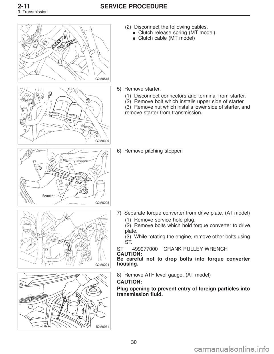
(2) Disconnect the following cables.
�Clutch release spring (MT model)
�Clutch cable (MT model)
G2M0309
5) Remove starter.
(1) Disconnect connectors and terminal from starter.
(2) Remove bolt which installs upper side of starter.
(3) Remove nut which installs lower side of starter, and
remove starter from transmission.
G2M0295
6) Remove pitching stopper.
G2M0294
7) Separate torque converter from drive plate. (AT model)
(1) Remove service hole plug.
(2) Remove bolts which hold torque converter to drive
plate.
(3) While rotating the engine, remove other bolts using
ST.
ST 499977000 CRANK PULLEY WRENCH
CAUTION:
Be careful not to drop bolts into torque converter
housing.
B2M0031
8) Remove ATF level gauge. (AT model)
CAUTION:
Plug opening to prevent entry of foreign particles into
transmission fluid.
30
2-11SERVICE PROCEDURE
3. Transmission
![SUBARU LEGACY 1996 Service Repair Manual 2-7
[16a2]
ON-BOARD
DIAGNOSTICS
11
SYSTEM
6
.
Wiring
Diagram
and
Wiring
Harness
2
.
AT
CONTROL
SYSTEM
To
Power
Supply
Routing
FB-20
~
FB-4
FB-15
~
FB-22
~
FB-30
FUSE
Na
15
FUSE
No
.
l6
FUSENa
lG](/manual-img/17/57433/w960_57433-64.png "SUBARU LEGACY 1996 Service Repair Manual 2-7
[16a2]
ON-BOARD
DIAGNOSTICS
11
SYSTEM
6
.
Wiring
Diagram
and
Wiring
Harness
2
.
AT
CONTROL
SYSTEM
To
Power
Supply
Routing
FB-20
~
FB-4
FB-15
~
FB-22
~
FB-30
FUSE
Na
15
FUSE
No
.
l6
FUSENa
lG")