1996 CHRYSLER VOYAGER transmission
[x] Cancel search: transmissionPage 1312 of 1938
INSTALLATION
(1) Position fuel tank on transmission jack. Con-
nect pressure relief/rollover valve hose. Connect fuel
filler tube vent hose and replace clamp.
(2) Raise tank into position and carefully work
filler tube into tank. A light coating of clean engine
oil on the tube end may be used to aid assembly.
(3) Feed filler vent line thru frame rail. Careful
not to cross lines.
(4) Tighten strap bolts to 54 N´m (40 ft. lbs.)
torque. Remove transmission jack.
(5) Tighten filler hose clamp to 3.3 N´m (30 in.
lbs.).
CAUTION: Ensure straps are not twisted or bent
before or after tightening strap nuts.
(6) Connect fuel pump/module electrical connector.
Place retainer in locked position.
(7) Lubricate the fuel supply line with clean 30
weight engine oil, install the quick connect fuel fit-
ting. Refer to Tube/Fitting Assembly in the Fuel
Delivery section of this Group.
(8) Attach filler line to filler tube. Pull on connec-
tor to make sure of connection.
(9) Fill fuel tank, replace cap, and connect battery
negative cable.
CAUTION: When using the ASD Fuel System Test,
the ASD relay and fuel pump relay remain energized
for 7 minutes or until the test is stopped, or until
the ignition switch is turned to the Off position.
(10) Use the DRB scan tool ASD Fuel System Test
to pressurize the fuel system. Check for leaks.
FUEL INJECTOR RAILÐ2.4L
REMOVAL
(1) Perform fuel system pressure release procedure
before servicing or starting repairs.Refer to
Fuel System Pressure Release Procedure in this sec-
tion.
(2) Disconnect negative cable from battery.
(3) Remove air cleaner inlet hose from throttle
body.
(4) Remove throttle cable and speed control cable
(if equipped) from throttle lever.
(5) Remove throttle cables from bracket by com-
pressing retaining tabs.
(6) Remove connector from throttle position sensor.
(7) Remove connector from idle air control motor.
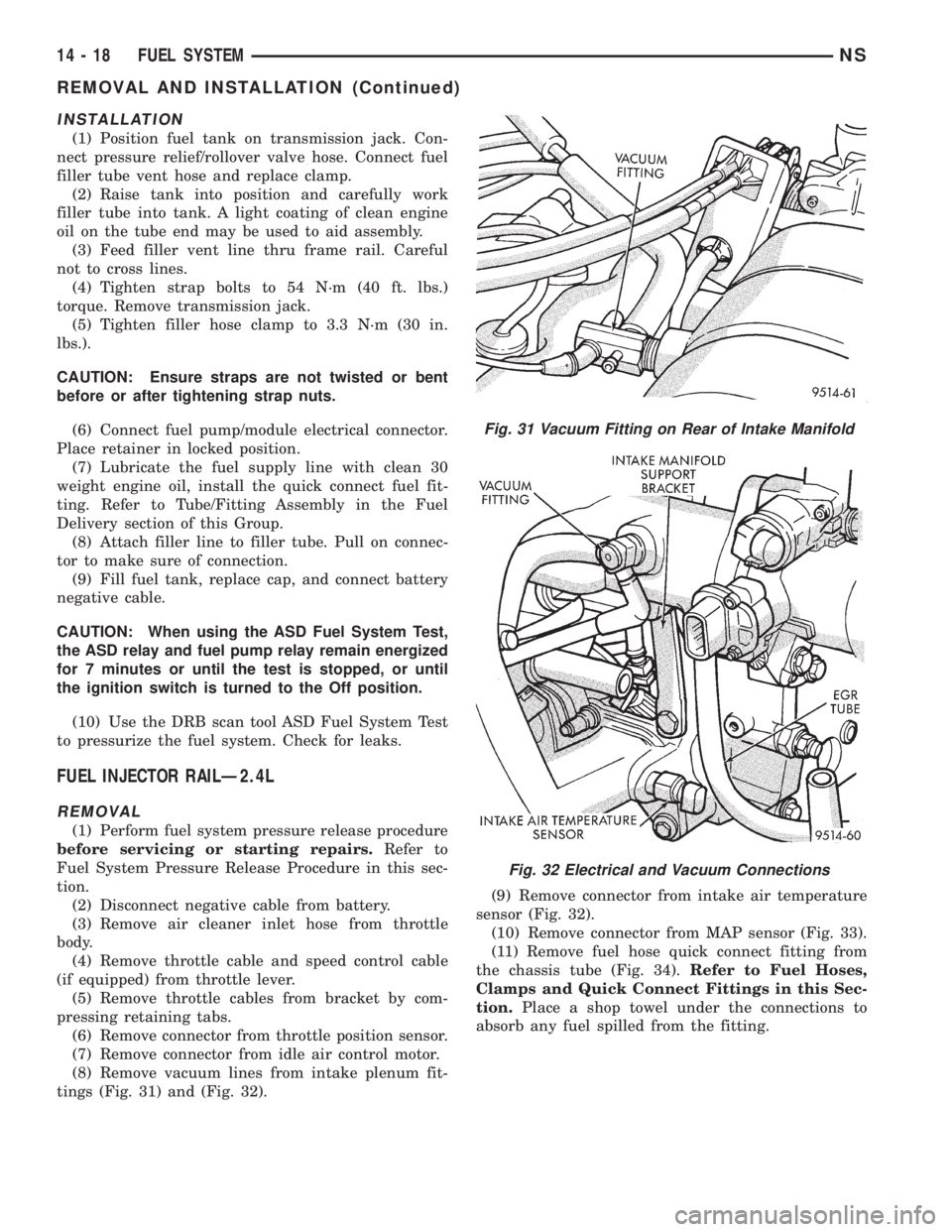
(8) Remove vacuum lines from intake plenum fit-
tings (Fig. 31) and (Fig. 32).(9) Remove connector from intake air temperature
sensor (Fig. 32).
(10) Remove connector from MAP sensor (Fig. 33).
(11) Remove fuel hose quick connect fitting from
the chassis tube (Fig. 34).Refer to Fuel Hoses,
Clamps and Quick Connect Fittings in this Sec-
tion.Place a shop towel under the connections to
absorb any fuel spilled from the fitting.
Fig. 31 Vacuum Fitting on Rear of Intake Manifold
Fig. 32 Electrical and Vacuum Connections
14 - 18 FUEL SYSTEMNS
REMOVAL AND INSTALLATION (Continued)
Page 1326 of 1938
IGNITION SWITCH OFF MODE
When the ignition switch is turned to the OFF
position, the following occurs:
²All outputs are turned off.
²No inputs are monitored.
²The PCM shuts down.
DESCRIPTION AND OPERATION
SYSTEM DIAGNOSIS
The PCM can test many of its own input and out-
put circuits. If the PCM senses a fault in a major
system, the PCM stores a Diagnostic Trouble Code
(DTC) in memory.
For DTC information, refer to Group 25, Emission
Control Systems. See On-Board Diagnostics.
CCD BUS
Various controllers and modules exchange informa-
tion through a communications port called the CCD
Bus. The PCM transmits the malfunction indicator
(check engine) lamp On/Off signal, engine RPM and
vehicle load information on the CCD Bus.
POWERTRAIN CONTROL MODULE (PCM)
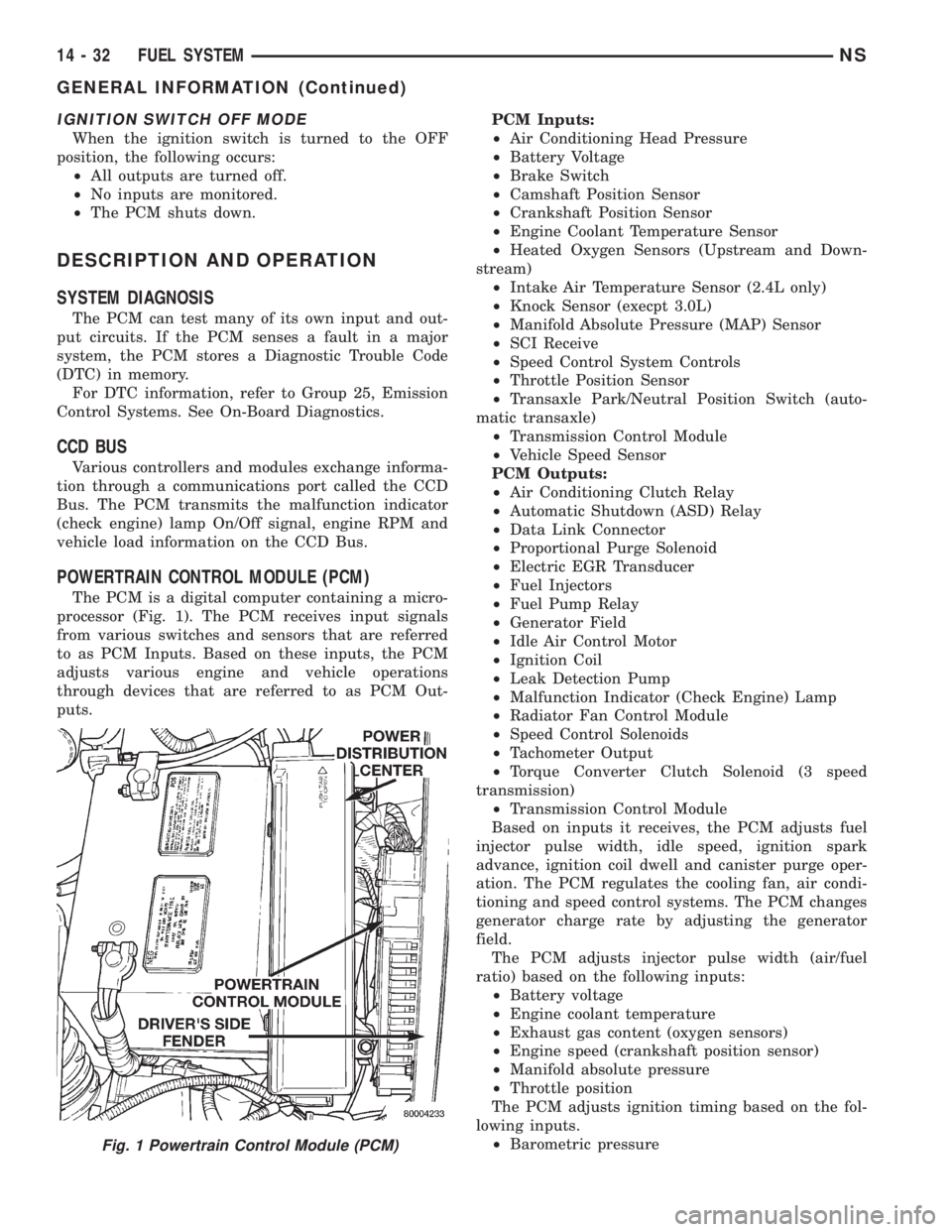
The PCM is a digital computer containing a micro-
processor (Fig. 1). The PCM receives input signals
from various switches and sensors that are referred
to as PCM Inputs. Based on these inputs, the PCM
adjusts various engine and vehicle operations
through devices that are referred to as PCM Out-
puts.PCM Inputs:
²Air Conditioning Head Pressure
²Battery Voltage
²Brake Switch
²Camshaft Position Sensor
²Crankshaft Position Sensor
²Engine Coolant Temperature Sensor
²Heated Oxygen Sensors (Upstream and Down-
stream)
²Intake Air Temperature Sensor (2.4L only)
²Knock Sensor (execpt 3.0L)
²Manifold Absolute Pressure (MAP) Sensor
²SCI Receive
²Speed Control System Controls
²Throttle Position Sensor
²Transaxle Park/Neutral Position Switch (auto-
matic transaxle)
²Transmission Control Module
²Vehicle Speed Sensor
PCM Outputs:
²Air Conditioning Clutch Relay
²Automatic Shutdown (ASD) Relay
²Data Link Connector
²Proportional Purge Solenoid
²Electric EGR Transducer
²Fuel Injectors
²Fuel Pump Relay
²Generator Field
²Idle Air Control Motor
²Ignition Coil
²Leak Detection Pump
²Malfunction Indicator (Check Engine) Lamp
²Radiator Fan Control Module
²Speed Control Solenoids
²Tachometer Output
²Torque Converter Clutch Solenoid (3 speed
transmission)
²Transmission Control Module
Based on inputs it receives, the PCM adjusts fuel
injector pulse width, idle speed, ignition spark
advance, ignition coil dwell and canister purge oper-
ation. The PCM regulates the cooling fan, air condi-
tioning and speed control systems. The PCM changes
generator charge rate by adjusting the generator
field.
The PCM adjusts injector pulse width (air/fuel
ratio) based on the following inputs:
²Battery voltage
²Engine coolant temperature
²Exhaust gas content (oxygen sensors)
²Engine speed (crankshaft position sensor)
²Manifold absolute pressure
²Throttle position
The PCM adjusts ignition timing based on the fol-
lowing inputs.
²Barometric pressure
Fig. 1 Powertrain Control Module (PCM)
14 - 32 FUEL SYSTEMNS
GENERAL INFORMATION (Continued)
Page 1383 of 1938
²High±pressure fuel line connections are loosened
or lines replaced
²Initial engine start±up or start±up after an
extended period of no engine operation
²Running fuel tank empty
FUEL INJECTION PUMP BLEEDING
(1) If the fuel injection pump has been replaced,
air should be bled at the overflow valve before
attempting to start engine.
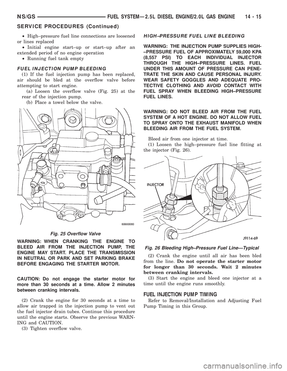
(a) Loosen the overflow valve (Fig. 25) at the
rear of the injection pump.
(b) Place a towel below the valve.
WARNING: WHEN CRANKING THE ENGINE TO
BLEED AIR FROM THE INJECTION PUMP, THE
ENGINE MAY START. PLACE THE TRANSMISSION
IN NEUTRAL OR PARK AND SET PARKING BRAKE
BEFORE ENGAGING THE STARTER MOTOR.
CAUTION: Do not engage the starter motor for
more than 30 seconds at a time. Allow 2 minutes
between cranking intervals.
(2) Crank the engine for 30 seconds at a time to
allow air trapped in the injection pump to vent out
the fuel injector drain tubes. Continue this procedure
until the engine starts. Observe the previous WARN-
ING and CAUTION.
(3) Tighten overflow valve.
HIGH±PRESSURE FUEL LINE BLEEDING
WARNING: THE INJECTION PUMP SUPPLIES HIGH-
±PRESSURE FUEL OF APPROXIMATELY 59,000 KPA
(8,557 PSI) TO EACH INDIVIDUAL INJECTOR
THROUGH THE HIGH±PRESSURE LINES. FUEL
UNDER THIS AMOUNT OF PRESSURE CAN PENE-
TRATE THE SKIN AND CAUSE PERSONAL INJURY.
WEAR SAFETY GOGGLES AND ADEQUATE PRO-
TECTIVE CLOTHING AND AVOID CONTACT WITH
FUEL SPRAY WHEN BLEEDING HIGH±PRESSURE
FUEL LINES.
WARNING: DO NOT BLEED AIR FROM THE FUEL
SYSTEM OF A HOT ENGINE. DO NOT ALLOW FUEL
TO SPRAY ONTO THE EXHAUST MANIFOLD WHEN
BLEEDING AIR FROM THE FUEL SYSTEM.
Bleed air from one injector at time.
(1) Loosen the high±pressure fuel line fitting at
the injector (Fig. 26).
(2) Crank the engine until all air has been bled
from the line.Do not operate the starter motor
for longer than 30 seconds. Wait 2 minutes
between cranking intervals.
(3) Start the engine and bleed one injector at a
time until the engine runs smoothly.
FUEL INJECTION PUMP TIMING
Refer to Removal/Installation and Adjusting Fuel
Pump Timing in this Group.
Fig. 25 Overflow Valve
Fig. 26 Bleeding High±Pressure Fuel LineÐTypical
NS/GSFUEL SYSTEMÐ2.5L DIESEL ENGINE/2.0L GAS ENGINE 14 - 15
SERVICE PROCEDURES (Continued)
Page 1392 of 1938
(4) Raise vehicle on hoist.
(5) Disconnect both the fuel fill and fuel vent rub-
ber hoses at the fuel tank.
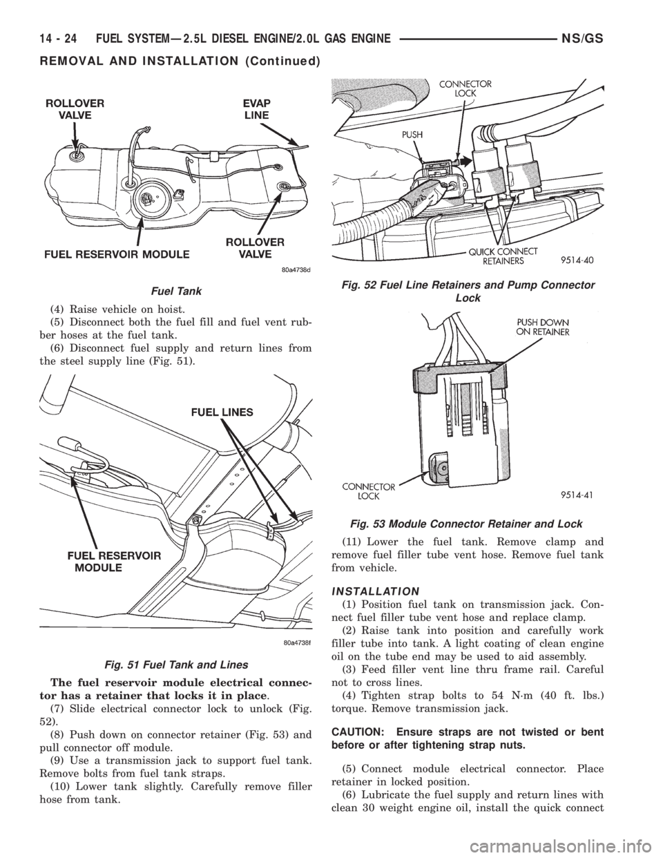
(6) Disconnect fuel supply and return lines from
the steel supply line (Fig. 51).
The fuel reservoir module electrical connec-
tor has a retainer that locks it in place.
(7) Slide electrical connector lock to unlock (Fig.
52).
(8) Push down on connector retainer (Fig. 53) and
pull connector off module.
(9) Use a transmission jack to support fuel tank.
Remove bolts from fuel tank straps.
(10) Lower tank slightly. Carefully remove filler
hose from tank.(11) Lower the fuel tank. Remove clamp and
remove fuel filler tube vent hose. Remove fuel tank
from vehicle.
INSTALLATION
(1) Position fuel tank on transmission jack. Con-
nect fuel filler tube vent hose and replace clamp.
(2) Raise tank into position and carefully work
filler tube into tank. A light coating of clean engine
oil on the tube end may be used to aid assembly.
(3) Feed filler vent line thru frame rail. Careful
not to cross lines.
(4) Tighten strap bolts to 54 N´m (40 ft. lbs.)
torque. Remove transmission jack.
CAUTION: Ensure straps are not twisted or bent
before or after tightening strap nuts.
(5) Connect module electrical connector. Place
retainer in locked position.
(6) Lubricate the fuel supply and return lines with
clean 30 weight engine oil, install the quick connect
Fuel Tank
Fig. 51 Fuel Tank and Lines
Fig. 52 Fuel Line Retainers and Pump Connector
Lock
Fig. 53 Module Connector Retainer and Lock
14 - 24 FUEL SYSTEMÐ2.5L DIESEL ENGINE/2.0L GAS ENGINENS/GS
REMOVAL AND INSTALLATION (Continued)
Page 1393 of 1938
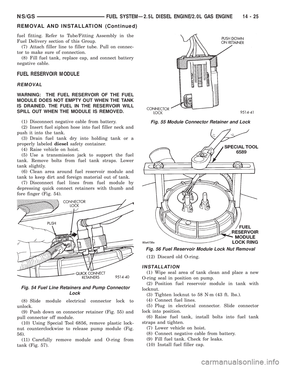
fuel fitting. Refer to Tube/Fitting Assembly in the
Fuel Delivery section of this Group.
(7) Attach filler line to filler tube. Pull on connec-
tor to make sure of connection.
(8) Fill fuel tank, replace cap, and connect battery
negative cable.
FUEL RESERVOIR MODULE
REMOVAL
WARNING: THE FUEL RESERVOIR OF THE FUEL
MODULE DOES NOT EMPTY OUT WHEN THE TANK
IS DRAINED. THE FUEL IN THE RESERVOIR WILL
SPILL OUT WHEN THE MODULE IS REMOVED.
(1) Disconnect negative cable from battery.
(2) Insert fuel siphon hose into fuel filler neck and
push it into the tank.
(3) Drain fuel tank dry into holding tank or a
properly labeleddieselsafety container.
(4) Raise vehicle on hoist.
(5) Use a transmission jack to support the fuel
tank. Remove bolts from fuel tank straps. Lower
tank slightly.
(6) Clean area around fuel reservoir module and
tank to keep dirt and foreign material out of tank.
(7) Disconnect fuel lines from fuel module by
depressing quick connect retainers with thumb and
fore finger (Fig. 54).
(8) Slide module electrical connector lock to
unlock.
(9) Push down on connector retainer (Fig. 55) and
pull connector off module.
(10) Using Special Tool 6856, remove plastic lock-
nut counterclockwise to release pump module (Fig.
56).
(11) Carefully remove module and O-ring from
tank (Fig. 57).(12) Discard old O-ring.
INSTALLATION
(1) Wipe seal area of tank clean and place a new
O-ring seal in position on pump.
(2) Position fuel reservoir module in tank with
locknut.
(3) Tighten locknut to 58 N´m (43 ft. lbs.).
(4) Connect fuel lines.
(5) Plug in electrical connector. Slide connector
lock into position.
(6) Raise fuel tank, install bolts into fuel tank
straps and tighten.
(7) Lower vehicle on hoist.
(8) Connect negative cable from battery.
(9) Fill fuel tank. Check for leaks.
(10) Install fuel filler cap.
Fig. 54 Fuel Line Retainers and Pump Connector
Lock
Fig. 55 Module Connector Retainer and Lock
Fig. 56 Fuel Reservoir Module Lock Nut Removal
NS/GSFUEL SYSTEMÐ2.5L DIESEL ENGINE/2.0L GAS ENGINE 14 - 25
REMOVAL AND INSTALLATION (Continued)
Page 1415 of 1938
AIR CONDITIONING (A/C) CONTROLSÐPCM
INPUTS
The A/C control system information applies to fac-
tory installed air conditioning units.
A/C REQUEST SIGNAL:When either the A/C or
Defrost mode has been selected and the A/C low and
high±pressure switches are closed, an input signal is
sent to the powertrain control module (PCM). The
PCM uses this input to cycle the A/C compressor
through the A/C relay.
If the A/C low or high±pressure switch opens, the
PCM will not receive an A/C request signal. The
PCM will then remove the ground from the A/C relay.
This will deactivate the A/C compressor clutch. Also,
if the engine coolant reaches a temperature outside
normal of its normal range, or it overheats, the PCM
will deactivate the A/C clutch.
BRAKE SWITCHÐPCM INPUT
When the brake light switch is activated, the PCM
receives an input indicating that the brakes are
being applied. After receiving this input, the PCM is
used to control the speed control system. There is a
Primary and a Secondary brake switch. The Second-
ary brake switch is closed until the brake pedal is
pressed.
DATA LINK CONNECTORÐPCM INPUT AND
OUTPUT
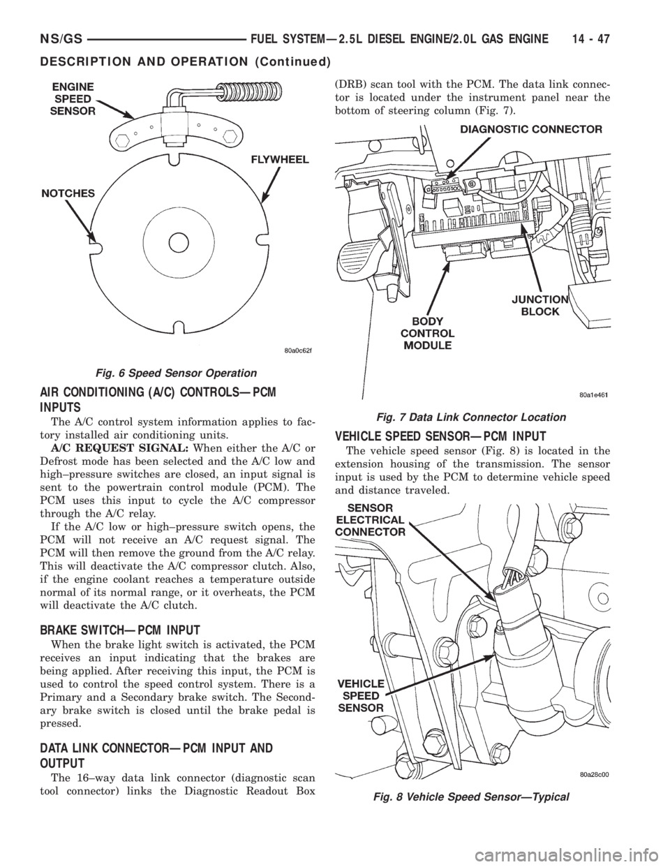
The 16±way data link connector (diagnostic scan
tool connector) links the Diagnostic Readout Box(DRB) scan tool with the PCM. The data link connec-
tor is located under the instrument panel near the
bottom of steering column (Fig. 7).
VEHICLE SPEED SENSORÐPCM INPUT
The vehicle speed sensor (Fig. 8) is located in the
extension housing of the transmission. The sensor
input is used by the PCM to determine vehicle speed
and distance traveled.
Fig. 6 Speed Sensor Operation
Fig. 7 Data Link Connector Location
Fig. 8 Vehicle Speed SensorÐTypical
NS/GSFUEL SYSTEMÐ2.5L DIESEL ENGINE/2.0L GAS ENGINE 14 - 47
DESCRIPTION AND OPERATION (Continued)
Page 1422 of 1938
(2) Remove the sensor mounting bolts.
(3) Remove the sensor.
INSTALLATION
(1) Install the sensor flush against the opening in
the transmission housing.
(2) Install and tighten the sensor mounting bolt to
19 N´m (14 ft. lbs.) torque.
(3) Connect the electrical connector to the sensor.
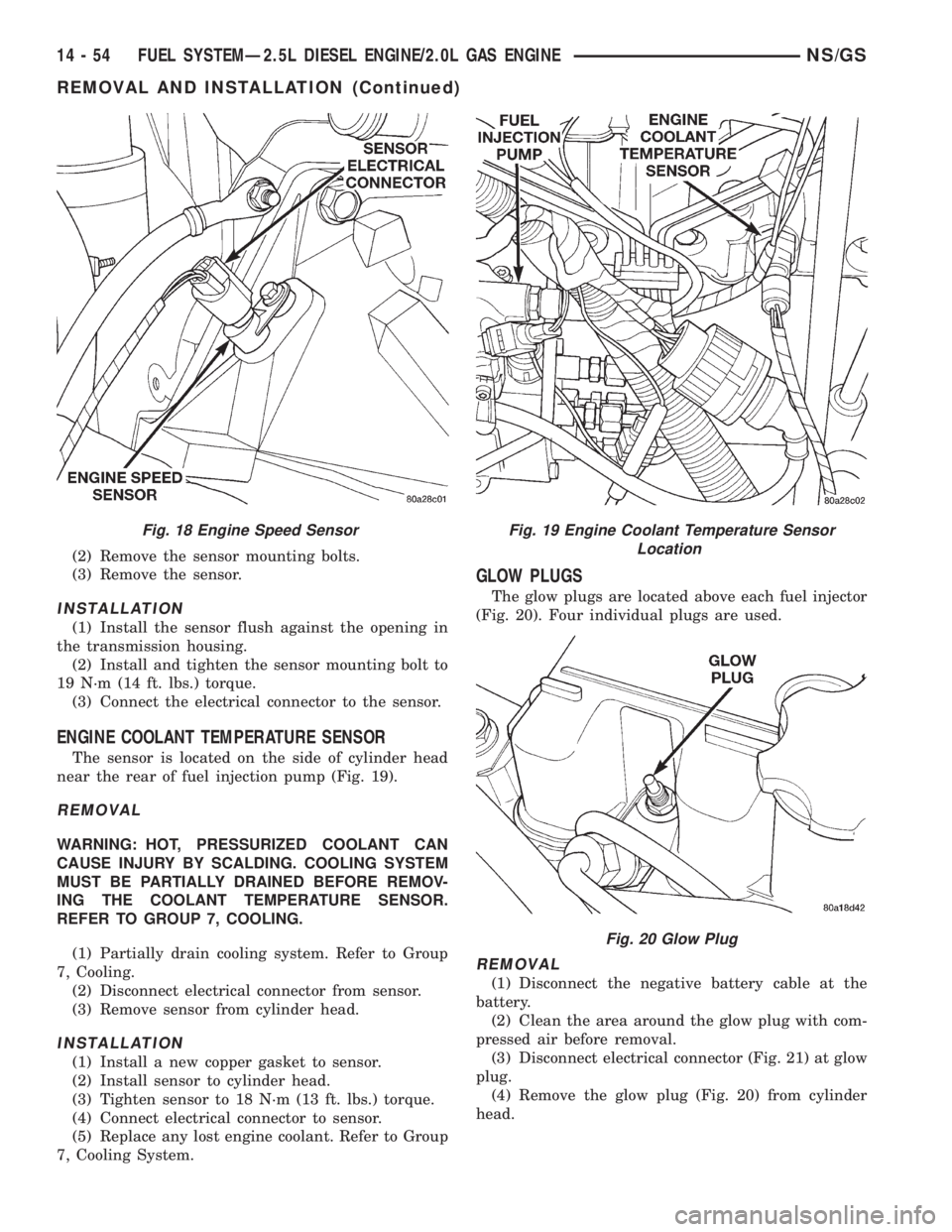
ENGINE COOLANT TEMPERATURE SENSOR
The sensor is located on the side of cylinder head
near the rear of fuel injection pump (Fig. 19).
REMOVAL
WARNING: HOT, PRESSURIZED COOLANT CAN
CAUSE INJURY BY SCALDING. COOLING SYSTEM
MUST BE PARTIALLY DRAINED BEFORE REMOV-
ING THE COOLANT TEMPERATURE SENSOR.
REFER TO GROUP 7, COOLING.
(1) Partially drain cooling system. Refer to Group
7, Cooling.
(2) Disconnect electrical connector from sensor.
(3) Remove sensor from cylinder head.
INSTALLATION
(1) Install a new copper gasket to sensor.
(2) Install sensor to cylinder head.
(3) Tighten sensor to 18 N´m (13 ft. lbs.) torque.
(4) Connect electrical connector to sensor.
(5) Replace any lost engine coolant. Refer to Group
7, Cooling System.
GLOW PLUGS
The glow plugs are located above each fuel injector
(Fig. 20). Four individual plugs are used.
REMOVAL
(1) Disconnect the negative battery cable at the
battery.
(2) Clean the area around the glow plug with com-
pressed air before removal.
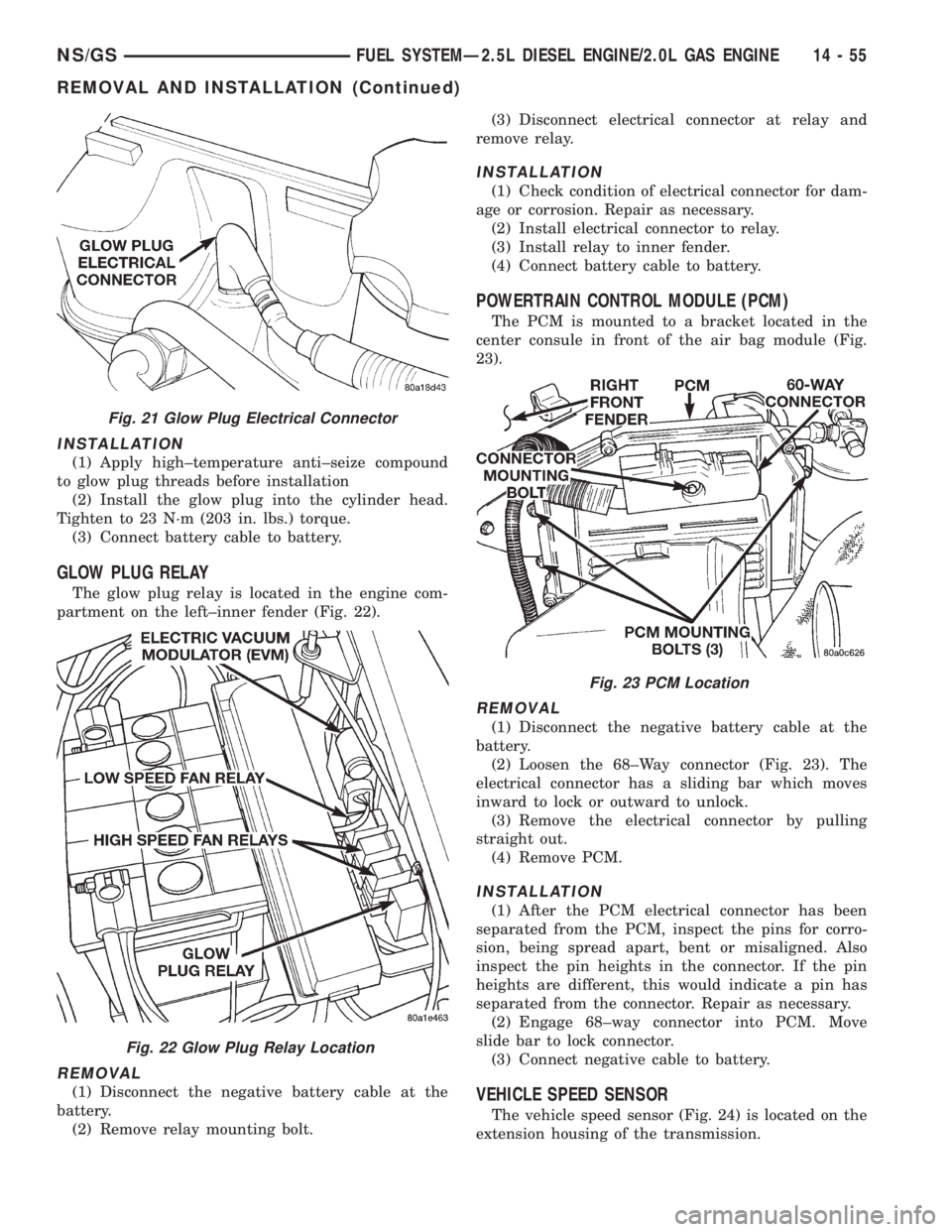
(3) Disconnect electrical connector (Fig. 21) at glow
plug.
(4) Remove the glow plug (Fig. 20) from cylinder
head.
Fig. 18 Engine Speed SensorFig. 19 Engine Coolant Temperature Sensor
Location
Fig. 20 Glow Plug
14 - 54 FUEL SYSTEMÐ2.5L DIESEL ENGINE/2.0L GAS ENGINENS/GS
REMOVAL AND INSTALLATION (Continued)
Page 1423 of 1938
INSTALLATION
(1) Apply high±temperature anti±seize compound
to glow plug threads before installation
(2) Install the glow plug into the cylinder head.
Tighten to 23 N´m (203 in. lbs.) torque.
(3) Connect battery cable to battery.
GLOW PLUG RELAY
The glow plug relay is located in the engine com-
partment on the left±inner fender (Fig. 22).
REMOVAL
(1) Disconnect the negative battery cable at the
battery.
(2) Remove relay mounting bolt.(3) Disconnect electrical connector at relay and
remove relay.
INSTALLATION
(1) Check condition of electrical connector for dam-
age or corrosion. Repair as necessary.
(2) Install electrical connector to relay.
(3) Install relay to inner fender.
(4) Connect battery cable to battery.
POWERTRAIN CONTROL MODULE (PCM)
The PCM is mounted to a bracket located in the
center consule in front of the air bag module (Fig.
23).
REMOVAL
(1) Disconnect the negative battery cable at the
battery.
(2) Loosen the 68±Way connector (Fig. 23). The
electrical connector has a sliding bar which moves
inward to lock or outward to unlock.
(3) Remove the electrical connector by pulling
straight out.
(4) Remove PCM.
INSTALLATION
(1) After the PCM electrical connector has been
separated from the PCM, inspect the pins for corro-
sion, being spread apart, bent or misaligned. Also
inspect the pin heights in the connector. If the pin
heights are different, this would indicate a pin has
separated from the connector. Repair as necessary.
(2) Engage 68±way connector into PCM. Move
slide bar to lock connector.
(3) Connect negative cable to battery.
VEHICLE SPEED SENSOR
The vehicle speed sensor (Fig. 24) is located on the
extension housing of the transmission.
Fig. 21 Glow Plug Electrical Connector
Fig. 22 Glow Plug Relay Location
Fig. 23 PCM Location
NS/GSFUEL SYSTEMÐ2.5L DIESEL ENGINE/2.0L GAS ENGINE 14 - 55
REMOVAL AND INSTALLATION (Continued)