1996 CHRYSLER VOYAGER transmission
[x] Cancel search: transmissionPage 1561 of 1938
TRANSMISSION CONTROL MODULE
Do not interchange Transmission Control Modules
with previous year transmission control modules. If a
same year TCM is being used from a different vehi-
cle, the following procedures must be performed:
²Quick Learn Procedure
²Electronic Pinion Procedure
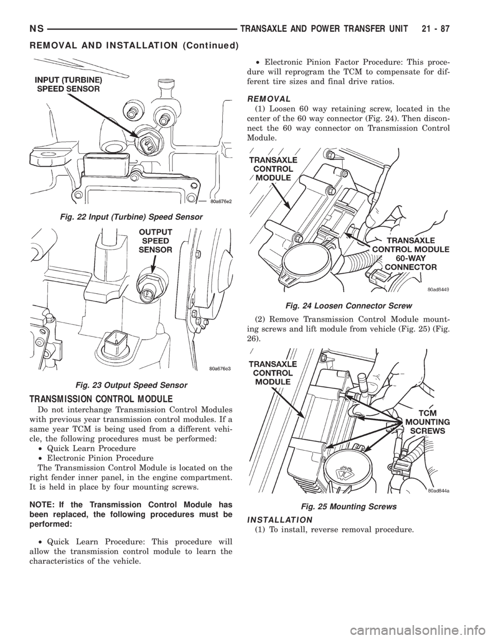
The Transmission Control Module is located on the
right fender inner panel, in the engine compartment.
It is held in place by four mounting screws.
NOTE: If the Transmission Control Module has
been replaced, the following procedures must be
performed:
²Quick Learn Procedure: This procedure will
allow the transmission control module to learn the
characteristics of the vehicle.²Electronic Pinion Factor Procedure: This proce-
dure will reprogram the TCM to compensate for dif-
ferent tire sizes and final drive ratios.
REMOVAL
(1) Loosen 60 way retaining screw, located in the
center of the 60 way connector (Fig. 24). Then discon-
nect the 60 way connector on Transmission Control
Module.
(2) Remove Transmission Control Module mount-
ing screws and lift module from vehicle (Fig. 25) (Fig.
26).
INSTALLATION
(1) To install, reverse removal procedure.
Fig. 22 Input (Turbine) Speed Sensor
Fig. 23 Output Speed Sensor
Fig. 24 Loosen Connector Screw
Fig. 25 Mounting Screws
NSTRANSAXLE AND POWER TRANSFER UNIT 21 - 87
REMOVAL AND INSTALLATION (Continued)
Page 1564 of 1938
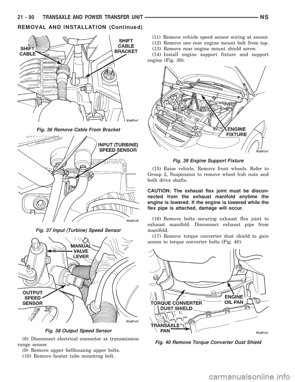
(8) Disconnect electrical connector at transmission
range sensor.
(9) Remove upper bellhousing upper bolts.
(10) Remove heater tube mounting bolt.(11) Remove vehicle speed sensor wiring at sensor.
(12) Remove one rear engine mount bolt from top.
(13) Remove rear engine mount shield screw.
(14) Install engine support fixture and support
engine (Fig. 39).
(15) Raise vehicle. Remove front wheels. Refer to
Group 2, Suspension to remove wheel hub nuts and
both drive shafts.
CAUTION: The exhaust flex joint must be discon-
nected from the exhaust manifold anytime the
engine is lowered. If the engine is lowered while the
flex pipe is attached, damage will occur.
(16) Remove bolts securing exhaust flex joint to
exhaust manifold. Disconnect exhaust pipe from
manifold.
(17) Remove torque converter dust shield to gain
access to torque converter bolts (Fig. 40).
Fig. 36 Remove Cable From Bracket
Fig. 37 Input (Turbine) Speed Sensor
Fig. 38 Output Speed Sensor
Fig. 39 Engine Support Fixture
Fig. 40 Remove Torque Converter Dust Shield
21 - 90 TRANSAXLE AND POWER TRANSFER UNITNS
REMOVAL AND INSTALLATION (Continued)
Page 1565 of 1938
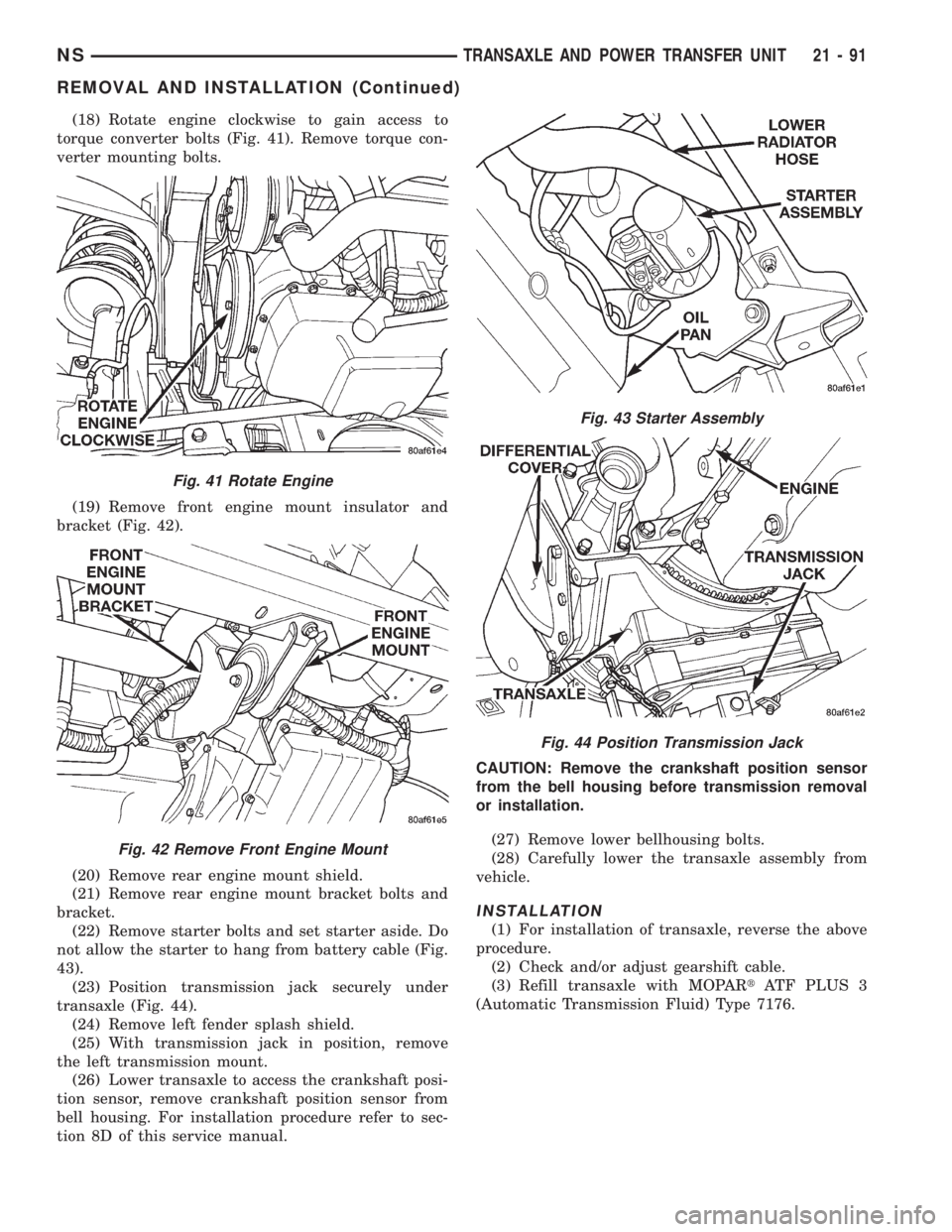
(18) Rotate engine clockwise to gain access to
torque converter bolts (Fig. 41). Remove torque con-
verter mounting bolts.
(19) Remove front engine mount insulator and
bracket (Fig. 42).
(20) Remove rear engine mount shield.
(21) Remove rear engine mount bracket bolts and
bracket.
(22) Remove starter bolts and set starter aside. Do
not allow the starter to hang from battery cable (Fig.
43).
(23) Position transmission jack securely under
transaxle (Fig. 44).
(24) Remove left fender splash shield.
(25) With transmission jack in position, remove
the left transmission mount.
(26) Lower transaxle to access the crankshaft posi-
tion sensor, remove crankshaft position sensor from
bell housing. For installation procedure refer to sec-
tion 8D of this service manual.CAUTION: Remove the crankshaft position sensor
from the bell housing before transmission removal
or installation.
(27) Remove lower bellhousing bolts.
(28) Carefully lower the transaxle assembly from
vehicle.
INSTALLATION
(1) For installation of transaxle, reverse the above
procedure.
(2) Check and/or adjust gearshift cable.
(3) Refill transaxle with MOPARtATF PLUS 3
(Automatic Transmission Fluid) Type 7176.
Fig. 41 Rotate Engine
Fig. 42 Remove Front Engine Mount
Fig. 43 Starter Assembly
Fig. 44 Position Transmission Jack
NSTRANSAXLE AND POWER TRANSFER UNIT 21 - 91
REMOVAL AND INSTALLATION (Continued)
Page 1566 of 1938
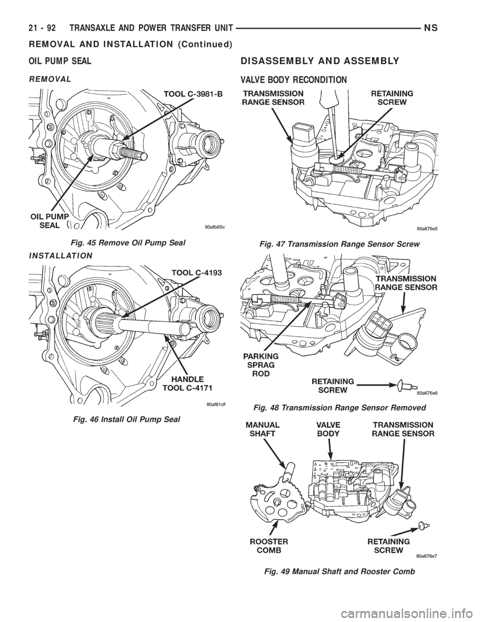
OIL PUMP SEAL
REMOVAL
INSTALLATION
DISASSEMBLY AND ASSEMBLY
VALVE BODY RECONDITION
Fig. 45 Remove Oil Pump Seal
Fig. 46 Install Oil Pump Seal
Fig. 47 Transmission Range Sensor Screw
Fig. 48 Transmission Range Sensor Removed
Fig. 49 Manual Shaft and Rooster Comb
21 - 92 TRANSAXLE AND POWER TRANSFER UNITNS
REMOVAL AND INSTALLATION (Continued)
Page 1632 of 1938
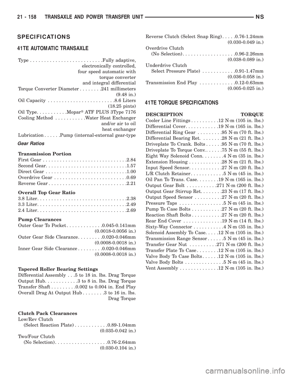
SPECIFICATIONS
41TE AUTOMATIC TRANSAXLE
Type..........................Fully adaptive,
electronically controlled,
four speed automatic with
torque converter
and integral differential
Torque Converter Diameter........241 millimeters
(9.48 in.)
Oil Capacity........................8.6 Liters
(18.25 pints)
OilType...........MopartATF PLUS 3Type 7176
Cooling Method...........Water Heat Exchanger
and/or air to oil
heat exchanger
Lubrication......Pump (internal-external gear-type
Gear Ratios
Transmission Portion
First Gear..............................2.84
Second Gear.............................1.57
Direct Gear.............................1.00
Overdrive Gear..........................0.69
Reverse Gear............................2.21
Overall Top Gear Ratio
3.8 Liter................................2.38
3.3 Liter................................2.49
2.4 Liter................................2.69
Pump Clearances
Outer Gear To Pocket.............0.045-0.141mm
(0.0018-0.0056 in.)
Outer Gear Side Clearance.........0.020-0.046mm
(0.0008-0.0018 in.)
Inner Gear Side Clearance.........0.020-0.046mm
(0.0008-0.0018 in.)
Tapered Roller Bearing Settings
Differential Assembly . . .5 to 18 in. lbs. Drag Torque
Output Hub............3to8in.lbs. Drag Torque
Transfer Shaft.........0.002 to 0.004 in. End Play
Overall Drag At Output Hub........3to16in.lbs.
Drag Torque
Clutch Pack Clearances
Low/Rev Clutch
(Select Reaction Plate)............0.89-1.04mm
(0.035-0.042 in.)
Two/Four Clutch
(No Selection)...................0.76-2.64mm
(0.030-0.104 in.)Reverse Clutch (Select Snap Ring).....0.76-1.24mm
(0.030-0.049 in.)
Overdrive Clutch
(No Selection)...................0.96-2.26mm
(0.038-0.089 in.)
Underdrive Clutch
Select Pressure Plate)............0.91-1.47mm
(0.036-0.058 in.)
Transmission End Play.............0.12-0.63mm
(0.005-0.025 in.)
41TE TORQUE SPECIFICATIONS
DESCRIPTION TORQUE
Cooler Line Fittings..........12N´m(105 in. lbs.)
Differential Cover............19N´m(165 in. lbs.)
Differential Ring Gear.........95N´m(70ft.lbs.)
Differential Bearing Ret........28N´m(21ft.lbs.)
Driveplate To Crank. Bolts......95N´m(70ft.lbs.)
Driveplate To Torque Conv.......75N´m(55ft.lbs.)
Eight Way Solenoid Conn........4N´m(35in.lbs.)
Extension Housing............28N´m(21ft.lbs.)
Input Speed Sensor............27N´m(20ft.lbs.)
L/R Clutch Retainer............5N´m(45in.lbs.)
Oil Pan To Trans. Case........19N´m(165 in. lbs.)
Output Gear Bolt...........271 N´m (200 ft. lbs.)
Output Gear Stirrup Ret........23N´m(17ft.lbs.)
Output Speed Sensor..........27N´m(20ft.lbs.)
Pressure Taps................5N´m(45in.lbs.)
Pump To Case Bolts...........27N´m(20ft.lbs.)
Reaction Shaft Bolts...........27N´m(20ft.lbs.)
Rear End Cover..............19N´m(14ft.lbs.)
Sixty-Way Connector...........4N´m(35in.lbs.)
Solenoid Assembly To Case.....12N´m(105 in. lbs.)
Transmission Range Sensor......5N´m(45in.lbs.)
Transfer Gear Nut..........271 N´m (200 ft. lbs.)
Transfer Plate To Case........12N´m(105 in. lbs.)
Valve Body To Case Bolts......12N´m(105 in. lbs.)
Valve Body Bolts..............5N´m(45in.lbs.)
Vent Assembly..............12N´m(105 in. lbs.)
21 - 158 TRANSAXLE AND POWER TRANSFER UNITNS
Page 1641 of 1938
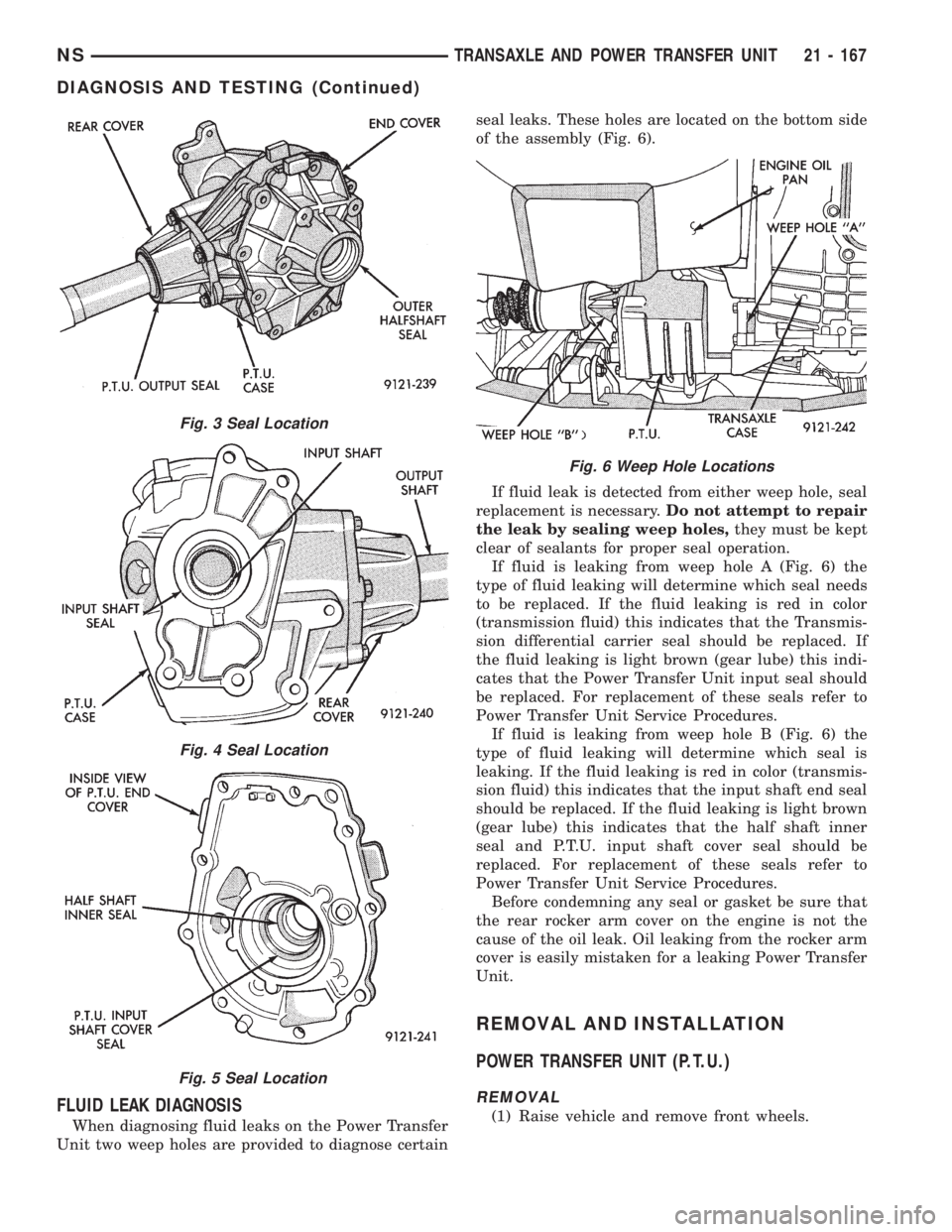
FLUID LEAK DIAGNOSIS
When diagnosing fluid leaks on the Power Transfer
Unit two weep holes are provided to diagnose certainseal leaks. These holes are located on the bottom side
of the assembly (Fig. 6).
If fluid leak is detected from either weep hole, seal
replacement is necessary.Do not attempt to repair
the leak by sealing weep holes,they must be kept
clear of sealants for proper seal operation.
If fluid is leaking from weep hole A (Fig. 6) the
type of fluid leaking will determine which seal needs
to be replaced. If the fluid leaking is red in color
(transmission fluid) this indicates that the Transmis-
sion differential carrier seal should be replaced. If
the fluid leaking is light brown (gear lube) this indi-
cates that the Power Transfer Unit input seal should
be replaced. For replacement of these seals refer to
Power Transfer Unit Service Procedures.
If fluid is leaking from weep hole B (Fig. 6) the
type of fluid leaking will determine which seal is
leaking. If the fluid leaking is red in color (transmis-
sion fluid) this indicates that the input shaft end seal
should be replaced. If the fluid leaking is light brown
(gear lube) this indicates that the half shaft inner
seal and P.T.U. input shaft cover seal should be
replaced. For replacement of these seals refer to
Power Transfer Unit Service Procedures.
Before condemning any seal or gasket be sure that
the rear rocker arm cover on the engine is not the
cause of the oil leak. Oil leaking from the rocker arm
cover is easily mistaken for a leaking Power Transfer
Unit.
REMOVAL AND INSTALLATION
POWER TRANSFER UNIT (P.T.U.)
REMOVAL
(1) Raise vehicle and remove front wheels.
Fig. 3 Seal Location
Fig. 4 Seal Location
Fig. 5 Seal Location
Fig. 6 Weep Hole Locations
NSTRANSAXLE AND POWER TRANSFER UNIT 21 - 167
DIAGNOSIS AND TESTING (Continued)
Page 1658 of 1938
GENERAL INFORMATION
A-598 MANUAL TRANSAXLE
Safety goggles should be worn at all times
when working on these transaxles.The A-598
manual transaxle uses SAE 5W-30 engine oil, meet-
ing SG and/or SG-CD qualifications, as the factory
fill lubricant. SAE G5 10W-40 engine oil is a suitable
service fill alternative.
This transaxle combines gear reduction, ratio selec-
tion, and differential functions in one unit. It is
housed in a die-cast aluminum case.
A-558 MANUAL TRANSAXLEÐRHD VEHICLES
Safety goggles should be worn at all times
when working on these transaxles.The A-558
manual transaxle uses SAE 5W-30 engine oil, meet-
ing SG and/or SG-CD qualifications, as the factory
fill lubricant. SAE G5 10W-40 engine oil is a suitable
service fill alternative.
This transaxle combines gear reduction, ratio selec-
tion, and differential functions in one unit. It is
housed in a die-cast aluminum case.
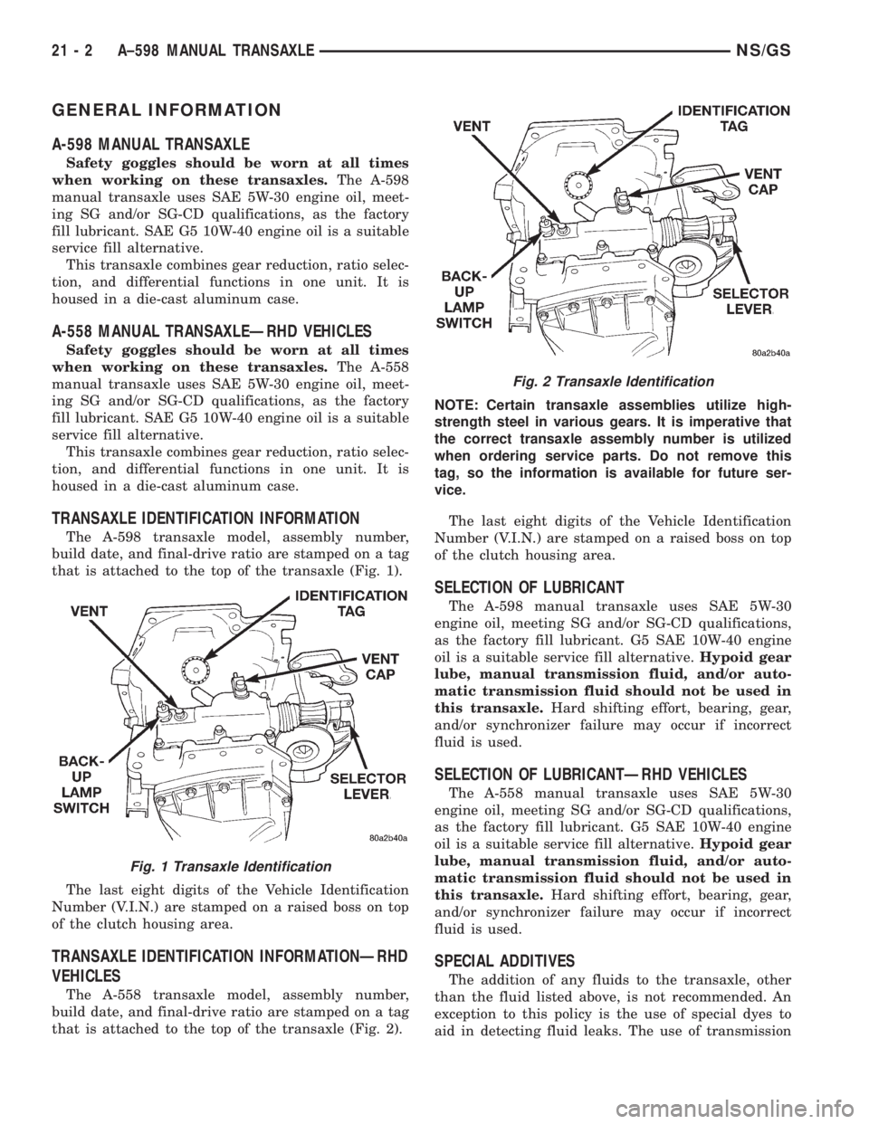
TRANSAXLE IDENTIFICATION INFORMATION
The A-598 transaxle model, assembly number,
build date, and final-drive ratio are stamped on a tag
that is attached to the top of the transaxle (Fig. 1).
The last eight digits of the Vehicle Identification
Number (V.I.N.) are stamped on a raised boss on top
of the clutch housing area.
TRANSAXLE IDENTIFICATION INFORMATIONÐRHD
VEHICLES
The A-558 transaxle model, assembly number,
build date, and final-drive ratio are stamped on a tag
that is attached to the top of the transaxle (Fig. 2).NOTE: Certain transaxle assemblies utilize high-
strength steel in various gears. It is imperative that
the correct transaxle assembly number is utilized
when ordering service parts. Do not remove this
tag, so the information is available for future ser-
vice.
The last eight digits of the Vehicle Identification
Number (V.I.N.) are stamped on a raised boss on top
of the clutch housing area.
SELECTION OF LUBRICANT
The A-598 manual transaxle uses SAE 5W-30
engine oil, meeting SG and/or SG-CD qualifications,
as the factory fill lubricant. G5 SAE 10W-40 engine
oil is a suitable service fill alternative.Hypoid gear
lube, manual transmission fluid, and/or auto-
matic transmission fluid should not be used in
this transaxle.Hard shifting effort, bearing, gear,
and/or synchronizer failure may occur if incorrect
fluid is used.
SELECTION OF LUBRICANTÐRHD VEHICLES
The A-558 manual transaxle uses SAE 5W-30
engine oil, meeting SG and/or SG-CD qualifications,
as the factory fill lubricant. G5 SAE 10W-40 engine
oil is a suitable service fill alternative.Hypoid gear
lube, manual transmission fluid, and/or auto-
matic transmission fluid should not be used in
this transaxle.Hard shifting effort, bearing, gear,
and/or synchronizer failure may occur if incorrect
fluid is used.
SPECIAL ADDITIVES
The addition of any fluids to the transaxle, other
than the fluid listed above, is not recommended. An
exception to this policy is the use of special dyes to
aid in detecting fluid leaks. The use of transmission
Fig. 1 Transaxle Identification
Fig. 2 Transaxle Identification
21 - 2 A±598 MANUAL TRANSAXLENS/GS
Page 1659 of 1938
sealers should be avoided, since they may adversely
affect seals.
SPECIAL ADDITIVESÐRHD VEHICLES
The addition of any fluids to the transaxle, other
than the fluid listed above, is not recommended. An
exception to this policy is the use of special dyes to
aid in detecting fluid leaks. The use of transmission
sealers should be avoided, since they may adversely
affect seals.
GEAR RATIOS
Gear ratios for the 2.4L gasoline engine and 2.5L
Turbo Diesel MTX are as follows:
²1stÐ3.36
²2ndÐ1.90
²3rdÐ1.28
²4thÐ0.92
²5thÐ0.71
²ReverseÐ3.17
Final drive ratio of 3.88 was selected for maximum
performance. All forward gears are synchronized.
Gear ratios for the 2.0L GAS MTX are as follows:
²1stÐ3.69
²2ndÐ2.24
²3rdÐ1.45
²4thÐ1.03
²5thÐ0.81
²ReverseÐ3.17
Final drive ratio of 4.08 was selected for maximum
performance. All forward gears are synchronized.
GEAR RATIOSÐRHD VEHICLES
Gear ratios for the 2.0L GAS MTX are as follows:
²1stÐ3.69
²2ndÐ2.24
²3rdÐ1.45
²4thÐ0.1.03
²5thÐ0.81
²ReverseÐ3.17
Final drive ratio of 4.08 was selected for maximum
performance. All forward gears are synchronized.
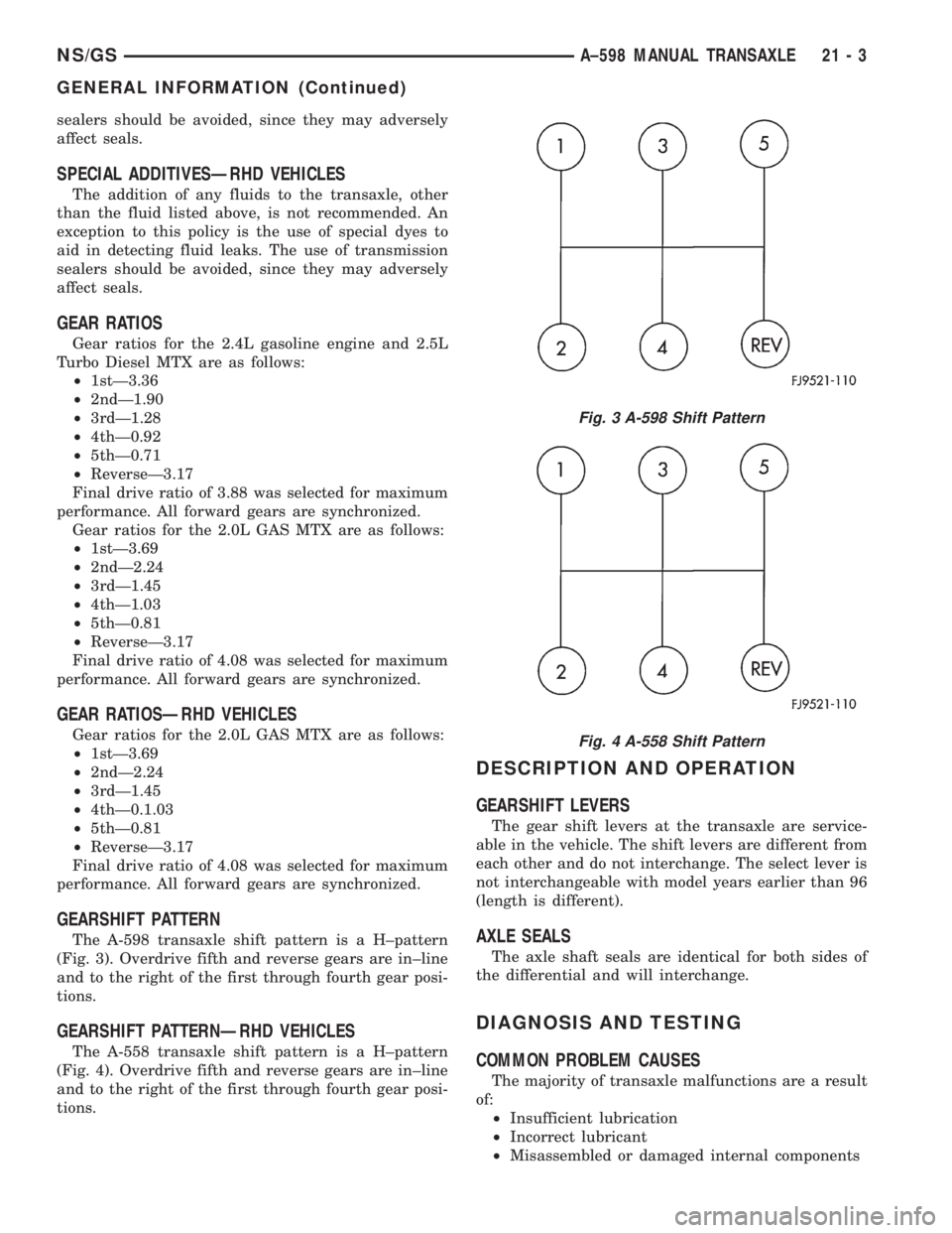
GEARSHIFT PATTERN
The A-598 transaxle shift pattern is a H±pattern
(Fig. 3). Overdrive fifth and reverse gears are in±line
and to the right of the first through fourth gear posi-
tions.
GEARSHIFT PATTERNÐRHD VEHICLES
The A-558 transaxle shift pattern is a H±pattern
(Fig. 4). Overdrive fifth and reverse gears are in±line
and to the right of the first through fourth gear posi-
tions.
DESCRIPTION AND OPERATION
GEARSHIFT LEVERS
The gear shift levers at the transaxle are service-
able in the vehicle. The shift levers are different from
each other and do not interchange. The select lever is
not interchangeable with model years earlier than 96
(length is different).
AXLE SEALS
The axle shaft seals are identical for both sides of
the differential and will interchange.
DIAGNOSIS AND TESTING
COMMON PROBLEM CAUSES
The majority of transaxle malfunctions are a result
of:
²Insufficient lubrication
²Incorrect lubricant
²Misassembled or damaged internal components
Fig. 3 A-598 Shift Pattern
Fig. 4 A-558 Shift Pattern
NS/GSA±598 MANUAL TRANSAXLE 21 - 3
GENERAL INFORMATION (Continued)