1996 CHRYSLER VOYAGER oil reset
[x] Cancel search: oil resetPage 109 of 1938

(4) Remove the locking pliers from the front park
brake cable. This will allow the adjuster in the park
brake pedal mechanism to rotate around to its stop.
This will remove the tension from the adjuster and
front park brake cable.
Use the following procedure to reset the auto
adjuster in the park brake pedal mechanism.
(5) Grasp the exposed section of the front park
brake cable and pull rearward on it. While holding
the park brake in this position, install a pair of lock-
ing pliers on the front park brake cable just rearward
of the second body outrigger bracket (Fig. 42).
(6) Install the equalizer on the front park brake
cable.
(7) Install the left rear and intermediate park
brake cable in the correct location on the park brake
cable equalizer (Fig. 43).
(8) Remove the locking pliers from the front park
brake cable. This will allow the adjuster in the park
brake pedal mechanism to tension the park brake
cables.
(9) Apply and release the park brake pedal one
time. This will seat the park brake cables and allow
the auto adjuster in the park brake pedal mechanism
to correctly tension the park brake cables.
REMOVAL AND INSTALLATION
WHEEL AND TIRE INSTALLATION
To install the wheel and tire assembly, first posi-
tion it properly on the mounting surface using the
hub pilot as a guide. Then progressively tighten thelug nuts in the proper sequence to half of the
required torque. Finally tighten the lug nuts in the
proper sequence to 129 N´m (95 ft. lbs.). Never use
oil or grease on studs or nuts.
FRONT DISC BRAKE CALIPER
SERVICE PRECAUTIONS
WARNING: ALTHOUGH FACTORY INSTALLED
BRAKE LININGS ARE MADE FROM ASBESTOS
FREE MATERIALS, SOME AFTER MARKET BRAKE
LINING MAY CONTAIN ASBESTOS. THIS SHOULD
BE TAKEN INTO ACCOUNT WHEN SERVICING A
VEHICLE'S BRAKE SYSTEM, WHEN AFTERMARKET
BRAKE LININGS MAY HAVE BEEN INSTALLED ON
THE VEHICLE. ALWAYS WEAR A RESPIRATOR
WHEN CLEANING BRAKE COMPONENTS AS
ASBESTOS CAN CAUSE SERIOUS BODILY HARM
SUCH AS ASBESTOSIS AND OR CANCER. NEVER
CLEAN BRAKE COMPONENTS BY USING COM-
PRESSED AIR, USE ONLY A VACUUM CLEANER
SPECIFICALLY DESIGNED FOR THE REMOVAL OF
BRAKE DUST. IF A VACUUM CLEANER IS NOT
AVAILABLE, CLEAN BRAKE PARTS USING ONLY
WATER±DAMPENED SHOP TOWELS. DO NOT CRE-
ATE BRAKELINING DUST BY SANDING BRAKE LIN-
INGS WHEN SERVICING A VEHICLE. DISPOSE OF
ALL DUST AND DIRT SUSPECTED OF CONTAINING
ASBESTOS FIBERS USING ONLY SEALED AIR-
TIGHT BAGS OR CONTAINERS. FOLLOW ALL REC-
OMMENDED SAFETY PRACTICES PRESCRIBED BY
THE OCCUPATIONAL SAFETY AND HEALTH ADMIN-
ISTRATION (OSHA) AND THE ENVIRONMENTAL
PROTECTION AGENCY (EPA), FOR HANDLING AND
DISPOSAL OF PRODUCTS CONTAINING ASBES-
TOS.
CAUTION: During service procedures, grease or
any other foreign material must be kept off brake
shoe assemblies, and braking surfaces of brake
drum and external surfaces of hub/bearing assem-
bly.
REMOVE
(1) Raise vehicle on jackstands or centered on a
hoist. See Hoisting in the Lubrication and Mainte-
nance group of this service manual.
(2) Remove front wheel and tire assemblies.
Fig. 43 Park Brake Cable Attachment To Equalizer
NSBRAKES 5 - 27
SERVICE PROCEDURES (Continued)
Page 545 of 1938

instrument cluster for 6 seconds after the instrument
cluster receives the message from the Body Control
Module. The seat belt lamp is therefore illuminated
for 6 seconds whenever the ignition switch is moved
to run/start position.
(1) While ignition is off, the seat belt lamp will not
be illuminated.
(2) The ignition power feed status will be updated
every 250 milliseconds or on change.
(3) This lamp will be checked by the instrument
cluster for 6 seconds with every run/start cycle of the
ignition switch.
TURN SIGNAL ON CHIME
The turn signal on chime will warn the driver that
the turn signals have been left on. When the body
control module receives a turn signal input for 6.4
km (4.0 miles), vehicle speed is greater than 24 km/h
(15 mph), the chime will sound continuously until the
turn signal is turned OFF. If vehicle speed drops
below 24 km/h (15 mph) prior to the warning being
activated, the accumulated distance traveled will be
reset. The turn signal chime is not activated when
the emergency flashers are turned on. This feature
can also be disabled in EEPROM. Chime rate: 50
chimes per minute.
For the turn signal warning system to operate:
²Must have input from either the right or left
turn signal lamps. Creates a voltage change between
0 and battery voltage.
²The vehicle speed sensor sends a message to the
Powertrain Control Module that vehicle has exceeded
24 km/h (15 mph) for 6.4 km (4.0 miles).
²When the above two conditions are met, the
chime will sound. The chime will stop when no fur-
ther voltage change is detected.²If hazard warning signals are pulsing, no chime
will sound.
²If speed drops below 24 km/h (15 mph) before
the warning is issued, the warning will not be issued
and the distance counter will be reset.
²If turn signal lamps are not working properly,
the chime will not sound.
²When using the scan tool, refer to the proper
Body Diagnostic Manual for the procedure.
WARNING LAMP ANNOUNCEMENT CHIME
The warning lamp announcement chime will warn
the driver to scan the instrument cluster to observe
which warning lamp is illuminated. Whenever the
volts, low fuel, low washer/coolant level, door ajar or
gate ajar lamps are first illuminated, the chime will
sound one tone. The door/liftgate ajar warning lamp
announcement chime sounds only if the vehicle speed
is above 2 m.p.h.
Two seconds after ignition switch is turned ON or
until the seat belt warning chime ends, all warning
announcement chimes will be consolidated into one
warning announcement. This will occur 2 seconds
after the seat belt warning chime ends. If a warning
announcement should occur while another warning
chime in progress (turn signal, low oil pressure or
high speed warnings), no additional chimes will
sound after the chime in progress ends. All associ-
ated lamps will be illuminated, and the active chime
will be the warning announcement.
NSCHIME WARNING/REMINDER SYSTEM 8U - 3
DIAGNOSIS AND TESTING (Continued)
Page 549 of 1938

SEAT BELT CHIME
The seat belt chime will sound for 4 to 8 seconds,
when the ignition is turned on and the driver's seat
belt is not buckled (seat belt switch is closed to
ground). This is a reminder to the driver to buckle
the seat belt. The seat belt lamp is controlled by the
mechanical instrument cluster. The cluster will also
illuminate the seat belt warning lamp for 6 seconds.
Buckling the driver's seat belt before the time out
has expired will cause the chime to stop immediately.
Chime rate: 38 to 62 chimes per minute.
To test the seat belt warning system, the ignition
switch must be in the OFF position for 1 minute
before starting the test. Turn the ignition switch to
the on position with the driver's seat belt not buck-
led. The seat belt warning lamp should light and the
chime should sound 4 to 8 seconds.
SEAT BELT LAMP
The seat belt lamp in the instrument cluster sig-
nals the vehicle passengers to fasten their seat belts.
The seat belt lamp is illuminated directly by the
instrument cluster for 6 seconds after the instrument
cluster receives the message from the Body Control
Module. The seat belt lamp is therefore illuminated
for 6 seconds whenever the ignition switch is moved
to run/start position.
(1) While ignition is off, the seat belt lamp will not
be illuminated.
(2) The ignition power feed status will be updated
every 250 milliseconds or on change.
(3) This lamp will be checked by the instrument
cluster for 6 seconds with every run/start cycle of the
ignition switch.
TURN SIGNAL ON CHIME
The turn signal on chime will warn the driver that
the turn signals have been left on. When the Body
Control Module receives a turn signal input for 1.6
km (1.0 miles), vehicle speed is greater than 24 km/h
(15 mph), the chime will sound continuously until the
turn signal is turned OFF. If vehicle speed drops
below 24 km/h (15 mph) prior to the warning being
activated, the accumulated distance traveled will be
reset. The turn signal chime is not activated whenthe emergency flashers are turned on. This feature
can also be disabled in EEPROM. Chime rate: 38 to
62 chimes per minute.
For the turn signal warning system to operate:
²Must have input from either the right or left
turn signal lamps. Creates a voltage change between
0 and battery voltage.
²The vehicle speed sensor sends a message to the
Powertrain Control Module that vehicle has exceeded
24 km/h (15 mph) for 1.6 km (1.0 miles).
²When the above two conditions are met, the
chime will sound. The chime will stop when no fur-
ther voltage change is detected.
²If hazard warning signals are pulsing, no chime
will sound.
²If speed drops below 24 km/h (15 mph) before
the warning is issued, the warning will not be issued
and the distance counter will be reset.
²If turn signal lamps are not working properly,
the chime will not sound.
²When using the scan tool, refer to the proper
Body Diagnostic Manual for the procedure.
WARNING LAMP ANNOUNCEMENT CHIME
The warning lamp announcement chime will warn
the driver to scan the instrument cluster to observe
which warning lamp is illuminated. Whenever the
volts, low fuel, low washer fluid, coolant level (gas/
diesel), low coolant level, engine temperature high
(diesel only), door ajar or gate ajar lamps are first
illuminated, the chime will sound one tone. The door/
liftgate ajar warning lamp announcement chime
sounds only if the vehicle speed is above 2 m.p.h.
Two seconds after ignition switch is turned ON or
until the seat belt warning chime ends, all warning
announcement chimes will be consolidated into one
warning announcement. This will occur 2 seconds
after the seat belt warning chime ends. If a warning
announcement should occur while another warning
chime in progress (turn signal, low oil pressure or
high speed warnings), no additional chimes will
sound after the chime in progress ends. All associ-
ated lamps will be illuminated, and the active chime
will be the warning announcement.
NS/GSCHIME WARNING/REMINDER SYSTEM 8U - 3
DIAGNOSIS AND TESTING (Continued)
Page 1324 of 1938

THROTTLE BODY....................... 64
THROTTLE POSITION SENSOR............ 65
UPSTREAM OXYGEN SENSOR............. 68
SPECIFICATIONS
TORQUE.............................. 72SPECIAL TOOLS
FUEL................................. 72
GENERAL INFORMATION
INTRODUCTION
All engines used in this section have a sequential
Multi-Port Electronic Fuel Injection system. The MPI
system is computer regulated and provides precise
air/fuel ratios for all driving conditions. The Power-
train Control Module (PCM) operates the fuel injec-
tion system.
The PCM regulates:
²Ignition timing
²Air/fuel ratio
²Emission control devices
²Cooling fan
²Charging system
²Idle speed
²Vehicle speed control
Various sensors provide the inputs necessary for
the PCM to correctly operate these systems. In addi-
tion to the sensors, various switches also provide
inputs to the PCM.
All inputs to the PCM are converted into signals.
The PCM can adapt its programming to meet chang-
ing operating conditions.
Fuel is injected into the intake port above the
intake valve in precise metered amounts through
electrically operated injectors. The PCM fires the
injectors in a specific sequence. Under most operat-
ing conditions, the PCM maintains an air fuel ratio
of 14.7 parts air to 1 part fuel by constantly adjust-
ing injector pulse width. Injector pulse width is the
length of time the injector is open.
The PCM adjusts injector pulse width by opening
and closing the ground path to the injector. Engine
RPM (speed) and manifold absolute pressure (air
density) are the primary inputs that determine injec-
tor pulse width.
MODES OF OPERATION
As input signals to the PCM change, the PCM
adjusts its response to output devices. For example,
the PCM must calculate a different injector pulse
width and ignition timing for idle than it does for
Wide Open Throttle (WOT). There are several differ-
ent modes of operation that determine how the PCM
responds to the various input signals.
There are two different areas of operation, OPEN
LOOP and CLOSED LOOP.
During OPEN LOOP modes the PCM receives
input signals and responds according to preset PCMprogramming. Input from the oxygen (O2S) sensor is
not monitored during OPEN LOOP modes.
During CLOSED LOOP modes the PCM does mon-
itor the O2S sensor input. This input indicates to the
PCM whether or not the calculated injector pulse
width results in the ideal air/fuel ratio of 14.7 parts
air to 1 part fuel. By monitoring the exhaust oxygen
content through the O2S sensor, the PCM can fine
tune the injector pulse width. Fine tuning injector
pulse width allows the PCM to achieve optimum fuel
economy combined with low emissions.
The multi-port fuel injection system has the follow-
ing modes of operation:
²Ignition switch ON (zero RPM)
²Engine start-up
²Engine warm-up
²Cruise (Idle)
²Acceleration
²Deceleration
²Wide Open Throttle
²Ignition switch OFF
The engine start-up (crank), engine warm-up, and
wide open throttle modes are OPEN LOOP modes.
Under most operating conditions, the acceleration,
deceleration, and cruise modes,with the engine at
operating temperatureare CLOSED LOOP modes.
IGNITION SWITCH ON (ZERO RPM) MODE
When the multi-port fuel injection system is acti-
vated by the ignition switch, the following actions
occur:
²The PCM determines atmospheric air pressure
from the MAP sensor input to determine basic fuel
strategy.
²The PCM monitors the coolant temperature sen-
sor and throttle position sensor input. The PCM mod-
ifies fuel strategy based on this input.
When the key is in the ON position and the engine
is not running (zero rpm), the Automatic Shutdown
(ASD) relay and fuel pump relay are not energized.
Therefore battery voltage is not supplied to the fuel
pump, ignition coil, fuel injectors or oxygen sensor
heating element.
ENGINE START-UP MODE
This is an OPEN LOOP mode. The following
actions occur when the starter motor is engaged.
If the PCM receives the camshaft position sensor
and crankshaft position sensor signals, it energizes
the ASD relay and fuel pump relay. These relays sup-
ply battery voltage to the fuel pump, fuel injectors,
14 - 30 FUEL SYSTEMNS
SPECIFICATIONS (Continued)
Page 1525 of 1938

Inspect all valve springs for distortion and col-
lapsed coils. Inspect all valves and plugs for burrs,
nicks, and scores. Small nicks and scores may be
removed with crocus cloth, providing extreme care is
taken not to round off sharp edges. The sharpness of
these edges is vitally important. It prevents foreign
matter from lodging between valve and valve body.
This reduces the possibility of sticking. Inspect all
valves and plugs for freedom of operation in valve
body bores.
When bores, valves, and plugs are clean and dry,
the valves and plugs should fall freely in the bores.
The valve body bores do not change its dimensions
with use. Therefore, a valve body that was function-
ing properly when vehicle was new, will operate cor-
rectly if it is properly and thoroughly cleaned. There
is no need to replace valve body unless it is damaged
in handling.
ADJUSTMENTS
GEARSHIFT CABLE ADJUSTMENT
Lift and rotate the gearshift hand lever into the
park (P) gate position and remove the ignition key.
This confirms the shift lever is in the gated park (P)
position.
After confirming the park gate position, turn the
ignition switch. If the starter will operate, the park
gate position is correct. Move the shift lever into the
neutral (N) position. If the starter will operate in this
position, the linkage is properly adjusted. If the
starter fails to operate in either position, linkage
adjustment is required.
(1) Park the vehicle on level ground and set the
parking brake.
(2) Place the gearshift lever in park (P) gate posi-
tion and remove key.
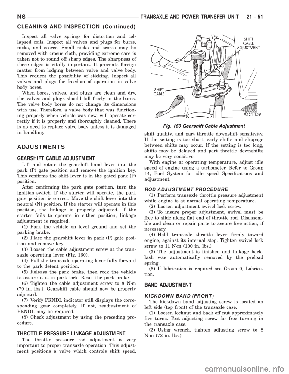
(3) Loosen the cable adjustment screw at the tran-
saxle operating lever (Fig. 160).
(4) Pull the transaxle operating lever fully forward
to the park detent position.
(5) Release the park brake, then rock the vehicle
to assure it is in park lock. Reset the park brake.
(6) Tighten the cable adjustment screw to 8 N´m
(70 in. lbs.). Gearshift cable should now be properly
adjusted.
(7) Verify PRNDL indicator still displays the corre-
sponding gear completely. If not, readjustment of
PRNDL may be required.
(8) Check adjustment by using the preceding pro-
cedure.
THROTTLE PRESSURE LINKAGE ADJUSTMENT
The throttle pressure rod adjustment is very
important to proper transaxle operation. This adjust-
ment positions a valve which controls shift speed,shift quality, and part throttle downshift sensitivity.
If the setting is too short, early shifts and slippage
between shifts may occur. If the setting is too long,
shifts may be delayed and part throttle downshifts
may be very sensitive.
With engine at operating temperature, adjust idle
speed of engine using a tachometer. Refer to Group
14, Fuel System for idle speed Specifications and
adjustment.
ROD ADJUSTMENT PROCEDURE
(1) Perform transaxle throttle pressure adjustment
while engine is at normal operating temperature.
(2) Loosen adjustment swivel lock screw.
(3) To insure proper adjustment, swivel must be
free to slide along flat end of throttle rod. Disassem-
ble and clean or repair parts to assure free action, if
necessary.
(4) Hold transaxle throttle lever firmly toward
engine, against its internal stop. Tighten swivel lock
screw to 11 N´m (100 in. lbs.)
(5) The adjustment is finished and linkage back-
lash was automatically removed by the preload
spring.
(6) I
f lubrication is required see Group 0, Lubrica-
tion.
BAND ADJUSTMENT
KICKDOWN BAND (FRONT)
The kickdown band adjusting screw is located on
left side (top front) of the transaxle case.
(1) Loosen locknut and back off nut approximately
five turns. Test adjusting screw for free turning in
the transaxle case.
(2) Using wrench, tighten adjusting screw to 8
N´m (72 in. lbs.).
Fig. 160 Gearshift Cable Adjustment
NSTRANSAXLE AND POWER TRANSFER UNIT 21 - 51
CLEANING AND INSPECTION (Continued)
Page 1557 of 1938

²The shift lever position must stay until
prompted to shift to overdrive
²The shift lever position must stay in overdrive
after the Shift to Overdrive prompt until the DRBIII
indicates the procedure is complete
²The calculated oil temperature must be above
60É and below 200É
(1) Plug the DRBIII scan tool into the data link
connector. The connector is located under the instru-
ment panel.
(2) Go to the Transmission screen.
(3) Go to the Miscellaneous screen.
(4) Select Quick Learn Procedure. Follow the
instructions of the DRBIII to perform the Quick
Learn Procedure.
PINION FACTOR PROCEDURE
The vehicle speed readings for the speedometer are
taken from the output speed sensor. The TCM must
be calibrated to the different combinations of equip-
ment available. A procedure has been developed
called Pinion Factor. It allows the technician to set
the Transmission Control Module initial setting so
that the speedometer readings will be correct.
Failure to perform this procedure will cause a No
Speedometer Operation condition.
This procedure must be performed if the Transmis-
sion Control Module has been replaced.
To properly read or reset the Pinion Factor, it is
necessary to use a DRBIII scan tool. Perform the fol-
lowing steps with the DRBIII scan tool to read or
reset the Pinion Factor:
(1) Plug the DRBIII scan tool into the data link
connector located under the instrument panel.
(2) Select the Transmission menu.
(3) Select the Miscellaneous menu.
(4) Select Pinion Factor. Then follow the instruc-
tions on the DRBIII scan tool screen.
REMOVAL AND INSTALLATION
GEARSHIFT CABLE
REMOVAL
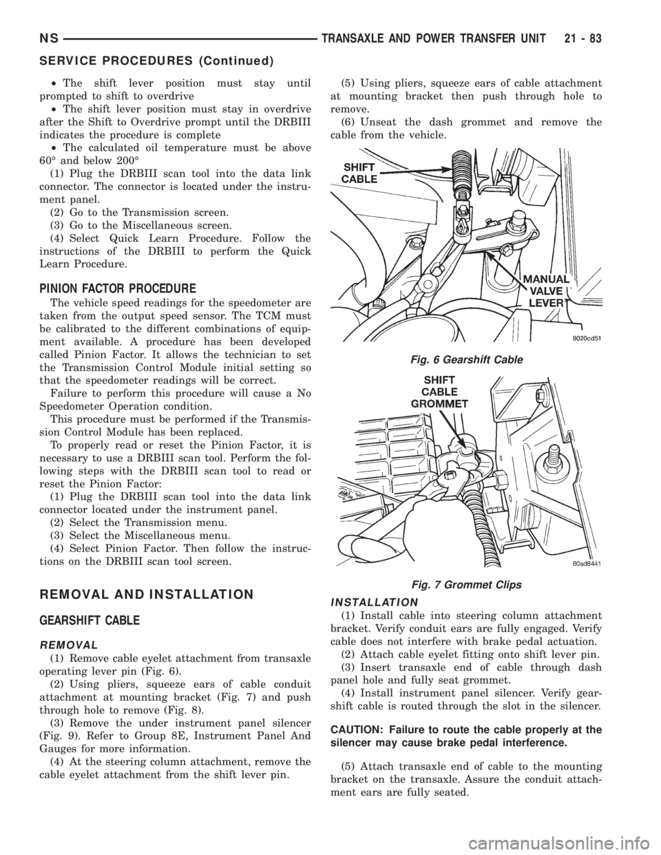
(1) Remove cable eyelet attachment from transaxle
operating lever pin (Fig. 6).
(2) Using pliers, squeeze ears of cable conduit
attachment at mounting bracket (Fig. 7) and push
through hole to remove (Fig. 8).
(3) Remove the under instrument panel silencer
(Fig. 9). Refer to Group 8E, Instrument Panel And
Gauges for more information.
(4) At the steering column attachment, remove the
cable eyelet attachment from the shift lever pin.(5) Using pliers, squeeze ears of cable attachment
at mounting bracket then push through hole to
remove.
(6) Unseat the dash grommet and remove the
cable from the vehicle.
INSTALLATION
(1) Install cable into steering column attachment
bracket. Verify conduit ears are fully engaged. Verify
cable does not interfere with brake pedal actuation.
(2) Attach cable eyelet fitting onto shift lever pin.
(3) Insert transaxle end of cable through dash
panel hole and fully seat grommet.
(4) Install instrument panel silencer. Verify gear-
shift cable is routed through the slot in the silencer.
CAUTION: Failure to route the cable properly at the
silencer may cause brake pedal interference.
(5) Attach transaxle end of cable to the mounting
bracket on the transaxle. Assure the conduit attach-
ment ears are fully seated.
Fig. 6 Gearshift Cable
Fig. 7 Grommet Clips
NSTRANSAXLE AND POWER TRANSFER UNIT 21 - 83
SERVICE PROCEDURES (Continued)
Page 1618 of 1938

(11) Install the oil baffle. Install the proper shim
combination under the bearing cup.
(12) Install the differential bearing retainer. Seal
the retainer to the housing with MopartSilicone
Rubber Adhesive Sealant. Torque bolts to 28 N´m
(250 in. lbs.).
(13) Using Miller Special Tool L-4436-A and an
inch-pound torque wrench, check the turning torque
of the differential (Fig. 299). The turning torque
should be between 5-18 inch-pounds.
NOTE: If turning torque is too high install a .05mm
(.002 inch) thicker shim. If the turning torque is too
low, install a .05mm (.002 inch) thinner shim. Repeat
until 5-18 inch-pounds of turning torque is
obtained.
CLEANING AND INSPECTION
CLEANING VALVE BODY
Prior to removing any transaxle parts, plug all
openings and clean unit, preferably by steam. Clean-
liness through entire disassembly and assembly can-
not be overemphasized. When disassembling, each
part should be washed in a suitable solvent, then
dried by compressed air.Do not wipe parts with
shop towels.All mating surfaces in the transaxles
are accurately machined; therefore, careful handling
of all parts must be exercised to avoid nicks or burrs.
NOTE: Tag all springs, as they are removed, for
reassembly identification.
ADJUSTMENTS
GEARSHIFT CABLE ADJUSTMENT
Lift and rotate the gearshift hand lever into the
park (P) gate position and remove the ignition key.This confirms the shift lever is in the gated park (P)
position.
After confirming the park gate position, turn the
ignition switch. If the starter will operate, the park
gate position is correct. Move the shift lever into the
neutral (N) position. If the starter will operate in this
position, the linkage is properly adjusted. If the
starter fails to operate in either position, linkage
adjustment is required.
(1) Park the vehicle on level ground and set the
parking brake.
(2) Place the gearshift lever in park (P) gate posi-
tion and remove key.
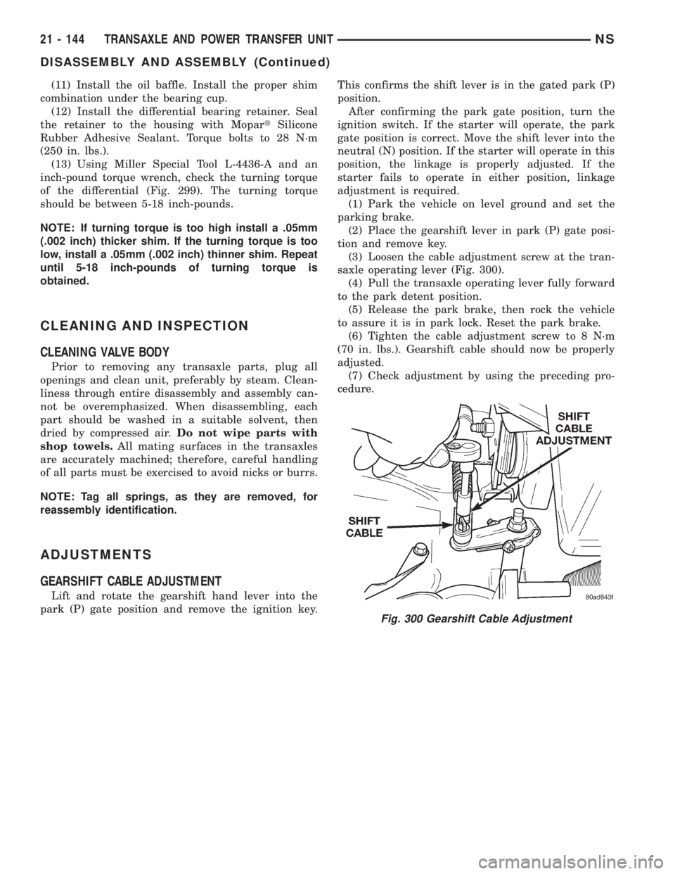
(3) Loosen the cable adjustment screw at the tran-
saxle operating lever (Fig. 300).
(4) Pull the transaxle operating lever fully forward
to the park detent position.
(5) Release the park brake, then rock the vehicle
to assure it is in park lock. Reset the park brake.
(6) Tighten the cable adjustment screw to 8 N´m
(70 in. lbs.). Gearshift cable should now be properly
adjusted.
(7) Check adjustment by using the preceding pro-
cedure.
Fig. 300 Gearshift Cable Adjustment
21 - 144 TRANSAXLE AND POWER TRANSFER UNITNS
DISASSEMBLY AND ASSEMBLY (Continued)