1996 CHRYSLER VOYAGER dimensions
[x] Cancel search: dimensionsPage 107 of 1938

flared end tubing.PLACE TUBE NUT ON TUB-
ING BEFORE FLARING THE TUBING.
DOUBLE INVERTED TUBING FLARES
To make a double inverted tubing flare (Fig. 39)
and (Fig. 40). Open handles of Flaring Tool, Special
Tool C-4047 or equivalent. Then rotate jaws of tool
until the mating jaws of tubing size are centered
between vertical posts on tool. Slowly close handles
with tubing inserted in jaws but do not apply heavy
pressure to handle as this will lock tubing in place.Place gauge (Form A) on edge over end of brake
tubing. Push tubing through jaws until end of tubing
contacts the recessed notch in gauge matching the
tubing size. Squeeze handles of flaring tool and lock
tubing in place. Place 3/16 inch plug of gauge (A)
down in end of tubing. Swing compression disc over
gauge and center tapered flaring screw in recess of
disc. Screw in until plug gauge has seated on jaws of
flaring tool. This action has started to invert the
extended end of the tubing. Remove gauge and con-
tinue to screw down until tool is firmly seated in tub-
ing. Remove tubing from flaring tool and inspect
seat. Refer to tube routing diagrams for proper brake
tube routing and clip locations. Replace any damaged
tube routing clips.
ISO TUBING FLARES
CAUTION: All ISO style tubing flares (Fig. 39) and
(Fig. 40) are of metric dimensions. When performing
any service procedures on vehicles using ISO style
tubing flares, metric size tubing of 4.75 mm MUST
be used with metric ISO tube flaring equipment.
To create a (metric) ISO style tubing flare, Use
Snap-On Flaring Tool TFM-428, or equivalent. See
(Fig. 41) and proceed with the steps listed below.Be
sure to place the tubing nut on the tube before
flaring the tubing.
(1) Carefully prepare the end of the tubing to be
flared. Be sure the end of the tubing to be flared is
square and all burrs on the inside of the tubing are
removed (Fig. 38).This preparation is essential to
Fig. 37 Cutting And Flaring Of Brake Fluid Tubing
Fig. 38 Brake Fluid Tube Preparation For Flaring
Fig. 39 Hydraulic Brake Tubing Flare Styles
NSBRAKES 5 - 25
SERVICE PROCEDURES (Continued)
Page 1072 of 1938
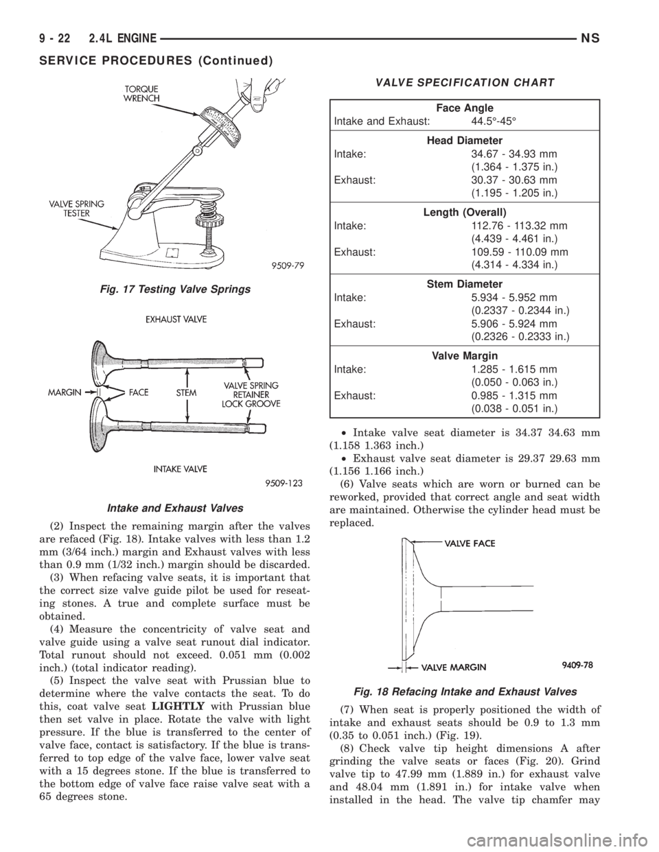
(2) Inspect the remaining margin after the valves
are refaced (Fig. 18). Intake valves with less than 1.2
mm (3/64 inch.) margin and Exhaust valves with less
than 0.9 mm (1/32 inch.) margin should be discarded.
(3) When refacing valve seats, it is important that
the correct size valve guide pilot be used for reseat-
ing stones. A true and complete surface must be
obtained.
(4) Measure the concentricity of valve seat and
valve guide using a valve seat runout dial indicator.
Total runout should not exceed. 0.051 mm (0.002
inch.) (total indicator reading).
(5) Inspect the valve seat with Prussian blue to
determine where the valve contacts the seat. To do
this, coat valve seatLIGHTLYwith Prussian blue
then set valve in place. Rotate the valve with light
pressure. If the blue is transferred to the center of
valve face, contact is satisfactory. If the blue is trans-
ferred to top edge of the valve face, lower valve seat
with a 15 degrees stone. If the blue is transferred to
the bottom edge of valve face raise valve seat with a
65 degrees stone.²Intake valve seat diameter is 34.37 34.63 mm
(1.158 1.363 inch.)
²Exhaust valve seat diameter is 29.37 29.63 mm
(1.156 1.166 inch.)
(6) Valve seats which are worn or burned can be
reworked, provided that correct angle and seat width
are maintained. Otherwise the cylinder head must be
replaced.
(7) When seat is properly positioned the width of
intake and exhaust seats should be 0.9 to 1.3 mm
(0.35 to 0.051 inch.) (Fig. 19).
(8) Check valve tip height dimensions A after
grinding the valve seats or faces (Fig. 20). Grind
valve tip to 47.99 mm (1.889 in.) for exhaust valve
and 48.04 mm (1.891 in.) for intake valve when
installed in the head. The valve tip chamfer may
Fig. 17 Testing Valve Springs
Intake and Exhaust Valves
VALVE SPECIFICATION CHART
Face Angle
Intake and Exhaust: 44.5É-45É
Head Diameter
Intake: 34.67 - 34.93 mm
(1.364 - 1.375 in.)
Exhaust: 30.37 - 30.63 mm
(1.195 - 1.205 in.)
Length (Overall)
Intake: 112.76 - 113.32 mm
(4.439 - 4.461 in.)
Exhaust: 109.59 - 110.09 mm
(4.314 - 4.334 in.)
Stem Diameter
Intake: 5.934 - 5.952 mm
(0.2337 - 0.2344 in.)
Exhaust: 5.906 - 5.924 mm
(0.2326 - 0.2333 in.)
Valve Margin
Intake: 1.285 - 1.615 mm
(0.050 - 0.063 in.)
Exhaust: 0.985 - 1.315 mm
(0.038 - 0.051 in.)
Fig. 18 Refacing Intake and Exhaust Valves
9 - 22 2.4L ENGINENS
SERVICE PROCEDURES (Continued)
Page 1073 of 1938
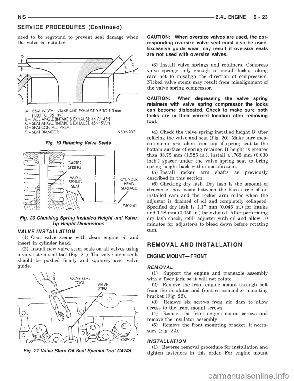
need to be reground to prevent seal damage when
the valve is installed.
VALVE INSTALLATION
(1) Coat valve stems with clean engine oil and
insert in cylinder head.
(2) Install new valve stem seals on all valves using
a valve stem seal tool (Fig. 21). The valve stem seals
should be pushed firmly and squarely over valve
guide.CAUTION: When oversize valves are used, the cor-
responding oversize valve seal must also be used.
Excessive guide wear may result if oversize seals
are not used with oversize valves.
(3) Install valve springs and retainers. Compress
valve springs only enough to install locks, taking
care not to misalign the direction of compression.
Nicked valve stems may result from misalignment of
the valve spring compressor.
CAUTION: When depressing the valve spring
retainers with valve spring compressor the locks
can become dislocated. Check to make sure both
locks are in their correct location after removing
tool.
(4) Check the valve spring installed height B after
refacing the valve and seat (Fig. 20). Make sure mea-
surements are taken from top of spring seat to the
bottom surface of spring retainer. If height is greater
than 38.75 mm (1.525 in.), install a .762 mm (0.030
inch.) spacer under the valve spring seat to bring
spring height back within specification.
(5) Install rocker arm shafts as previously
described in this section.
(6) Checking dry lash. Dry lash is the amount of
clearance that exists between the base circle of an
installed cam and the rocker arm roller when the
adjuster is drained of oil and completely collapsed.
Specified dry lash is 1.17 mm (0.046 in.) for intake
and 1.28 mm (0.050 in.) for exhaust. After performing
dry lash check, refill adjuster with oil and allow 10
minutes for adjuster/s to bleed down before rotating
cam.
REMOVAL AND INSTALLATION
ENGINE MOUNTÐFRONT
REMOVAL
(1) Support the engine and transaxle assembly
with a floor jack so it will not rotate.
(2) Remove the front engine mount through bolt
from the insulator and front crossmember mounting
bracket (Fig. 22).
(3) Remove six screws from air dam to allow
access to the front mount screws.
(4) Remove the front engine mount screws and
remove the insulator assembly.
(5) Remove the front mounting bracket, if neces-
sary (Fig. 22).
INSTALLATION
(1) Reverse removal procedure for installation and
tighten fasteners in this order. For engine mount
Fig. 19 Refacing Valve Seats
Fig. 20 Checking Spring Installed Height and Valve
Tip Height Dimensions
Fig. 21 Valve Stem Oil Seal Special Tool C4745
NS2.4L ENGINE 9 - 23
SERVICE PROCEDURES (Continued)
Page 1086 of 1938
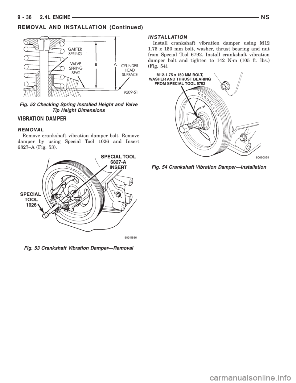
VIBRATION DAMPER
REMOVAL
Remove crankshaft vibration damper bolt. Remove
damper by using Special Tool 1026 and Insert
6827±A (Fig. 53).
INSTALLATION
Install crankshaft vibration damper using M12
1.75 x 150 mm bolt, washer, thrust bearing and nut
from Special Tool 6792. Install crankshaft vibration
damper bolt and tighten to 142 N´m (105 ft. lbs.)
(Fig. 54).
Fig. 52 Checking Spring Installed Height and Valve
Tip Height Dimensions
Fig. 53 Crankshaft Vibration DamperÐRemoval
Fig. 54 Crankshaft Vibration DamperÐInstallation
9 - 36 2.4L ENGINENS
REMOVAL AND INSTALLATION (Continued)
Page 1117 of 1938
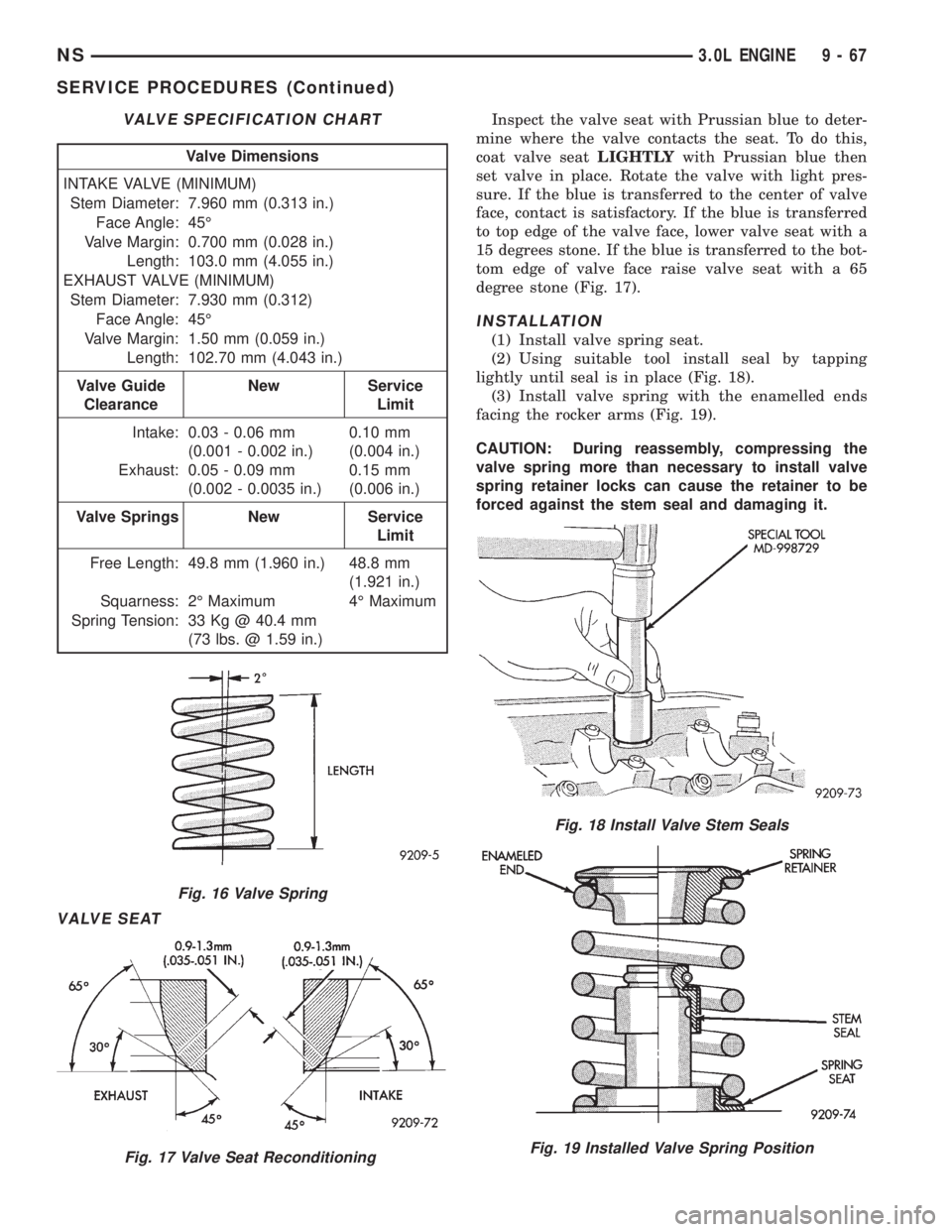
VALVE SEAT
Inspect the valve seat with Prussian blue to deter-
mine where the valve contacts the seat. To do this,
coat valve seatLIGHTLYwith Prussian blue then
set valve in place. Rotate the valve with light pres-
sure. If the blue is transferred to the center of valve
face, contact is satisfactory. If the blue is transferred
to top edge of the valve face, lower valve seat with a
15 degrees stone. If the blue is transferred to the bot-
tom edge of valve face raise valve seat with a 65
degree stone (Fig. 17).
INSTALLATION
(1) Install valve spring seat.
(2) Using suitable tool install seal by tapping
lightly until seal is in place (Fig. 18).
(3) Install valve spring with the enamelled ends
facing the rocker arms (Fig. 19).
CAUTION: During reassembly, compressing the
valve spring more than necessary to install valve
spring retainer locks can cause the retainer to be
forced against the stem seal and damaging it.
VALVE SPECIFICATION CHART
Valve Dimensions
INTAKE VALVE (MINIMUM)
Stem Diameter: 7.960 mm (0.313 in.)
Face Angle: 45É
Valve Margin: 0.700 mm (0.028 in.)
Length: 103.0 mm (4.055 in.)
EXHAUST VALVE (MINIMUM)
Stem Diameter: 7.930 mm (0.312)
Face Angle: 45É
Valve Margin: 1.50 mm (0.059 in.)
Length: 102.70 mm (4.043 in.)
Valve Guide
ClearanceNew Service
Limit
Intake: 0.03 - 0.06 mm
(0.001 - 0.002 in.)0.10 mm
(0.004 in.)
Exhaust: 0.05 - 0.09 mm
(0.002 - 0.0035 in.)0.15 mm
(0.006 in.)
Valve Springs New Service
Limit
Free Length: 49.8 mm (1.960 in.) 48.8 mm
(1.921 in.)
Squarness: 2É Maximum 4É Maximum
Spring Tension: 33 Kg @ 40.4 mm
(73 lbs. @ 1.59 in.)
Fig. 16 Valve Spring
Fig. 17 Valve Seat Reconditioning
Fig. 18 Install Valve Stem Seals
Fig. 19 Installed Valve Spring Position
NS3.0L ENGINE 9 - 67
SERVICE PROCEDURES (Continued)
Page 1160 of 1938
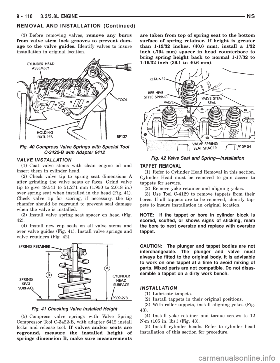
(3) Before removing valves,remove any burrs
from valve stem lock grooves to prevent dam-
age to the valve guides.Identify valves to insure
installation in original location.
VALVE INSTALLATION
(1) Coat valve stems with clean engine oil and
insert them in cylinder head.
(2) Check valve tip to spring seat dimensions A
after grinding the valve seats or faces. Grind valve
tip to give 49.541 to 51.271 mm (1.950 to 2.018 in.)
over spring seat when installed in the head (Fig. 41).
Check valve tip for scoring, if necessary, the tip
chamfer should be reground to prevent seal damage
when the valve is installed.
(3) Install valve spring seat spacer on head (Fig.
42).
(4) Install new cup seals on all valve stems and
over valve guides (Fig. 41). Install valve springs and
valve retainers (Fig. 42).
(5) Compress valve springs with Valve Spring
Compressor Tool C-3422-B, with adapter 6412 install
locks and release tool.If valves and/or seats are
reground, measure the installed height of
springs dimension B, make sure measurementsare taken from top of spring seat to the bottom
surface of spring retainer. If height is greater
than 1-19/32 inches, (40.6 mm), install a 1/32
inch (.794 mm) spacer in head counterbore to
bring spring height back to normal 1-17/32 to
1-19/32 inch (39.1 to 40.6 mm).TAPPET REMOVAL
(1) Refer to Cylinder Head Removal in this section.
Cylinder Head must be removed to gain access to
tappets for service.
(2) Remove yoke retainer and aligning yokes.
(3) Use Tool C-4129 to remove tappets from their
bores. If all tappets are to be removed, identify tap-
pets to insure installation in original location.
NOTE: If the tappet or bore in cylinder block is
scored, scuffed, or shows signs of sticking, ream
the bore to next oversize and replace with oversize
tappet.
CAUTION: The plunger and tappet bodies are not
interchangeable. The plunger and valve must
always be fitted to the original body. It is advisable
to work on one tappet at a time to avoid mixing of
parts. Mixed parts are not compatible. Do not disas-
semble a tappet on a dirty work bench.
INSTALLATION
(1) Lubricate tappets.
(2) Install tappets in their original positions.
(3) With roller tappets, install aligning yokes (Fig.
43).
(4) Install yoke retainer and torque screws to 12
N´m (105 in. lbs.) (Fig. 43).
(5) Install cylinder heads. Refer to cylinder head
installation of this section for procedure.
Fig. 40 Compress Valve Springs with Special Tool
C-3422-B with Adapter 6412
Fig. 41 Checking Valve Installed Height
Fig. 42 Valve Seal and SpringÐInstallation
9 - 110 3.3/3.8L ENGINENS
REMOVAL AND INSTALLATION (Continued)
Page 1209 of 1938
Total runout should not exceed. 0.051 mm (0.002
inch.) (total indicator reading).
(5) Inspect the valve seat with Prussian blue to
determine where the valve contacts the seat. To do
this, coat valve seatLIGHTLYwith Prussian blue
then set valve in place. Rotate the valve with light
pressure. If the blue is transferred to the center of
valve face, contact is satisfactory. If the blue is trans-
ferred to top edge of the valve face, lower valve seat
with a 15 degrees stone. If the blue is transferred to
the bottom edge of valve face raise valve seat with a
65 degrees stone.
²Intake valve seat diameter is 33 mm (1.299 in.)
²Exhaust valve seat diameter is 28 mm (1.102
in.)
(6) Valve seats which are worn or burned can be
reworked, provided that correct angle and seat width
are maintained. The intake valve seat must be ser-
viced when the valve seat width is 2.0 mm (0.079 in.)
or greater. The exhaust valve seat must be serviced
when the valve seat width is 2.5 mm (0.098 in.) or
greater. Otherwise the cylinder head must be
replaced.
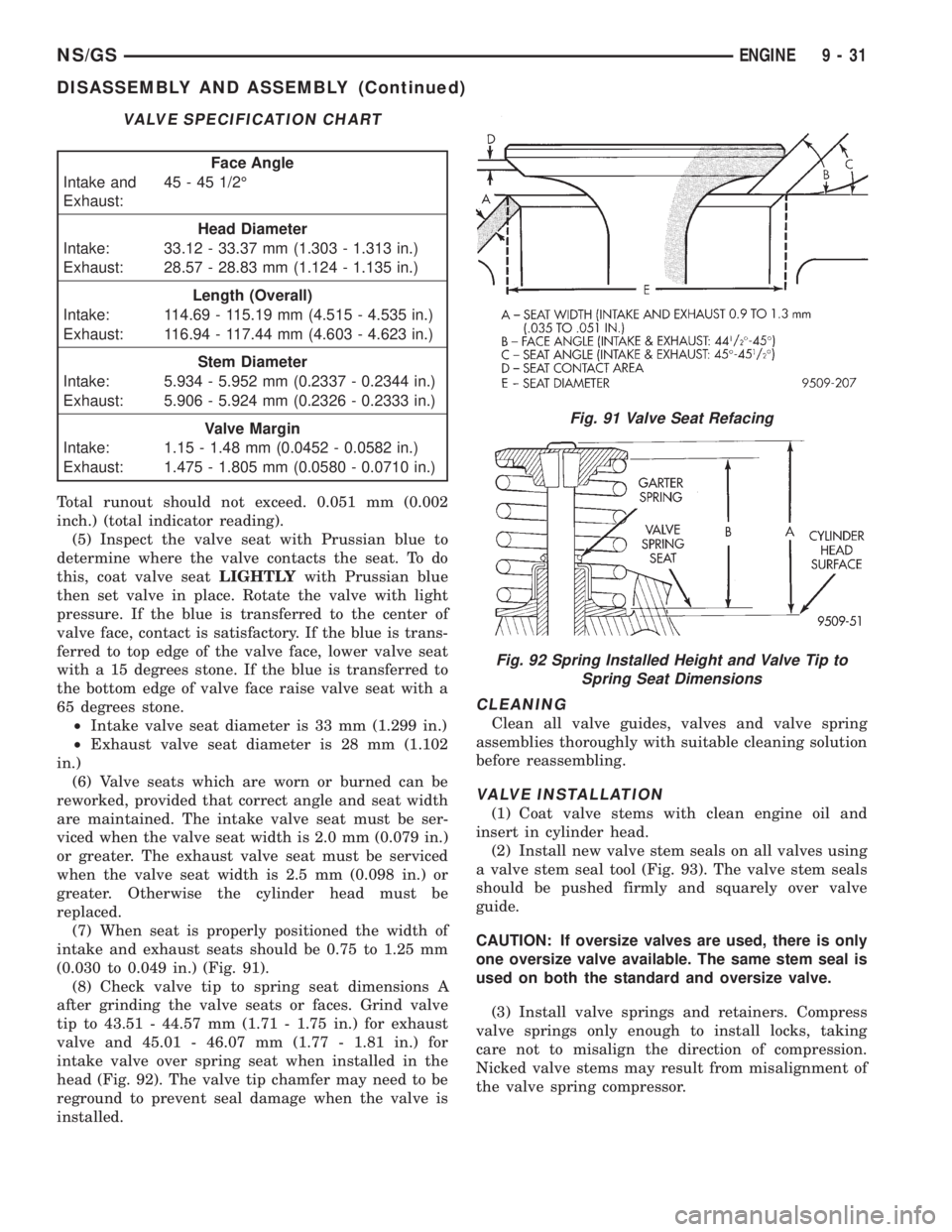
(7) When seat is properly positioned the width of
intake and exhaust seats should be 0.75 to 1.25 mm
(0.030 to 0.049 in.) (Fig. 91).
(8) Check valve tip to spring seat dimensions A
after grinding the valve seats or faces. Grind valve
tip to 43.51 - 44.57 mm (1.71 - 1.75 in.) for exhaust
valve and 45.01 - 46.07 mm (1.77 - 1.81 in.) for
intake valve over spring seat when installed in the
head (Fig. 92). The valve tip chamfer may need to be
reground to prevent seal damage when the valve is
installed.
CLEANING
Clean all valve guides, valves and valve spring
assemblies thoroughly with suitable cleaning solution
before reassembling.
VALVE INSTALLATION
(1) Coat valve stems with clean engine oil and
insert in cylinder head.
(2) Install new valve stem seals on all valves using
a valve stem seal tool (Fig. 93). The valve stem seals
should be pushed firmly and squarely over valve
guide.
CAUTION: If oversize valves are used, there is only
one oversize valve available. The same stem seal is
used on both the standard and oversize valve.
(3) Install valve springs and retainers. Compress
valve springs only enough to install locks, taking
care not to misalign the direction of compression.
Nicked valve stems may result from misalignment of
the valve spring compressor.
VALVE SPECIFICATION CHART
Face Angle
Intake and
Exhaust:45 - 45 1/2É
Head Diameter
Intake: 33.12 - 33.37 mm (1.303 - 1.313 in.)
Exhaust: 28.57 - 28.83 mm (1.124 - 1.135 in.)
Length (Overall)
Intake: 114.69 - 115.19 mm (4.515 - 4.535 in.)
Exhaust: 116.94 - 117.44 mm (4.603 - 4.623 in.)
Stem Diameter
Intake: 5.934 - 5.952 mm (0.2337 - 0.2344 in.)
Exhaust: 5.906 - 5.924 mm (0.2326 - 0.2333 in.)
Valve Margin
Intake: 1.15 - 1.48 mm (0.0452 - 0.0582 in.)
Exhaust: 1.475 - 1.805 mm (0.0580 - 0.0710 in.)
Fig. 91 Valve Seat Refacing
Fig. 92 Spring Installed Height and Valve Tip to
Spring Seat Dimensions
NS/GSENGINE 9 - 31
DISASSEMBLY AND ASSEMBLY (Continued)
Page 1283 of 1938
FRAME
INDEX
page page
REMOVAL AND INSTALLATION
FRONT CROSSMEMBER MOUNT BUSHINGS . . . 5
FRONT CROSSMEMBER................... 3SPECIFICATIONS
FRAME AND BODY OPENING DIMENSIONS.... 5
REMOVAL AND INSTALLATION
FRONT CROSSMEMBER
The front suspension crossmember must be
installed in the design location to achieve proper
front end suspension alignment. If the crossmember
is removed without applying reference marks on the
frame rails, align the crossmember according to the
dimensions provided in this group.
NOTE: If the caged nuts in the frame rails become
damaged and cannot be reused, a replacement nut
can be obtained through a MoparTParts supplier.
REMOVAL
(1) Disconnect battery negative cable.
(2) Remove steering column lower cover from
instrument panel. Refer to Group 8E, Instrument
Panel and Systems.
(3) Remove knee blocker reinforcement. Refer to
Group 8E, Instrument Panel and Systems.
(4) Position steering so front wheels are straight
ahead.
CAUTION: Do not rotate steering wheel after disen-
gaging lower coupling from steering gear, damage
to airbag clock spring can result.
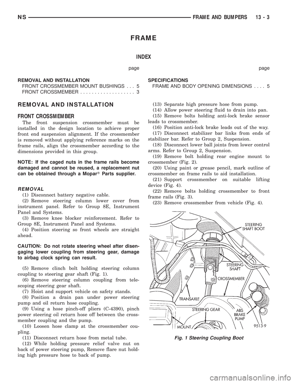
(5) Remove clinch bolt holding steering column
coupling to steering gear shaft (Fig. 1).
(6) Remove steering column coupling from tele-
scoping steering gear shaft.
(7) Hoist and support vehicle on safety stands.
(8) Position a drain pan under power steering
pump and oil return hose coupling.
(9) Using a hose pinch-off pliers (C-4390), pinch
power steering oil return hose off between the cross-
member coupling and the pump.
(10) Loosen hose clamp at the crossmember cou-
pling.
(11) Disconnect return hose from metal tube.
(12) While holding pressure relief valve nut on
back of power steering pump, Remove flare nut hold-
ing high pressure hose to back of pump.(13) Separate high pressure hose from pump.
(14) Allow power steering fluid to drain into pan.
(15) Remove bolts holding anti-lock brake sensor
leads to crossmember.
(16) Position anti-lock brake leads out of the way.
(17) Disconnect stabilizer bar links from ends of
stabilizer bar. Refer to Group 2, Suspension.
(18) Disconnect lower ball joints from lower control
arms. Refer to Group 2, Suspension.
(19) Remove bolt holding rear engine mount to
crossmember (Fig. 2).
(20) Using paint or grease pencil, mark outline of
crossmember on frame rails to aid installation.
(21) Support crossmember on suitable lifting
device (Fig. 4).
(22) Remove bolts holding crossmember to front
frame rails (Fig. 3).
(23) Remove crossmember from vehicle (Fig. 4).
Fig. 1 Steering Coupling Boot
NSFRAME AND BUMPERS 13 - 3