1996 CHRYSLER VOYAGER catalytic converter
[x] Cancel search: catalytic converterPage 306 of 1938

NOTE: Over or under tightening effects knock sen-
sor performance, possibly causing improper spark
control.
DIAGNOSIS AND TESTING
TESTING FOR SPARK AT COILÐ2.4/3.3/3.8L
ENGINES
WARNING: THE DIRECT IGNITION SYSTEMS GEN-
ERATES APPROXIMATELY 40,000 VOLTS. PER-
SONAL INJURY COULD RESULT FROM CONTACT
WITH THIS SYSTEM.
The coil pack contains independent coils. Each coil
must be checked individually.
CAUTION: Spark plug wire damage may occur if
the spark plug is moved more than 1/4 inch away
from the engine ground.
CAUTION: Do not leave any one spark plug cable
disconnected any longer than 30 seconds or possi-
ble heat damage to catalytic converter will occur.
CAUTION: Test must be performed at idle and in
park only with the parking brake on.
Use a new spark plug and spark plug cable
for the following test.
(1) Insert a new spark plug into the new spark
plug boot. Ground the plug to the engine (Fig. 15).
Do not hold with your hand.
(2) Starting with coil insulator #1, remove it from
the DIS coil.(3) Plug the test spark plug cable onto #1 coil
tower. Make sure a good connection is made; there
should be a click sound.
(4) Crank the engine and look for spark across the
electrodes of the spark plug.
CAUTION: Always install the cable back on the coil
tower after testing to avoid damage to the coil and
catalytic converter.
(5) Repeat the above test for the remaining coils. If
there is no spark during all cylinder tests, proceed to
the Failure To Start Test.
(6) If one or more tests indicate irregular, weak, or
no spark, proceed to Check Coil Test.
TESTING FOR SPARK AT COILÐ3.0L
WARNING: APPLY PARKING BRAKE AND/OR
BLOCK THE WHEELS BEFORE PERFORMING ANY
TEST WITH THE ENGINE RUNNING.
CAUTION: Spark plug cables may be damaged if
this test is performed with more than 1/4 inch clear-
ance between the cable and engine ground.
Remove the coil secondary cable from the distribu-
tor cap. Hold the end of cable about 6 mm (1/4-inch)
away from a good engine ground using non-conduc-
tive ignition pliers (Fig. 16). Crank the engine and
inspect for spark at the coil secondary cable.
There must be a constant spark at the coil second-
ary cable. If spark is not constant or there is no
spark, proceed to the failure to start test. If the
spark is constant, continue to crank engine and,
while slowly moving coil secondary cable away from
ground, look for arcing at the coil tower. If arcing
occurs at the tower, replace the coil.
If a constant spark is present and no arcing occurs
at the coil tower, the ignition system is producing the
necessary high secondary voltage. However, make
Fig. 15 Testing For Spark
Fig. 16 Checking for Spark
8D - 8 IGNITION SYSTEMNS
GENERAL INFORMATION (Continued)
Page 1263 of 1938
EXHAUST SYSTEM AND INTAKE MANIFOLD
CONTENTS
page page
GENERAL INFORMATION
CATALYTIC CONVERTERS................. 1
EXHAUST FLEX-JOINT COUPLING........... 2
EXHAUST GAS RECIRCULATION (EGR)....... 2
EXHAUST SYSTEM....................... 1
HEAT SHIELDS.......................... 2
DESCRIPTION AND OPERATION
INTAKE/EXHAUST MANIFOLDÐ2.4L ENGINE . . 3
INTAKE/EXHAUST MANIFOLDÐ3.0L ENGINE . . 3
INTAKE/EXHAUST MANIFOLDÐ3.3/3.8L
ENGINES............................. 3
DIAGNOSIS AND TESTING
EXHAUST SYSTEM....................... 3REMOVAL AND INSTALLATION
EXHAUST MANIFOLDÐ2.4L ENGINE........ 8
EXHAUST MANIFOLDÐ3.0L ENGINE....... 11
EXHAUST MANIFOLDSÐ3.3/3.8L ENGINE . . . 16
EXHAUST PIPES, MUFFLERS AND TAILPIPES . 4
INTAKE MANIFOLD LOWERÐ2.4L ENGINE.... 6
INTAKE MANIFOLDÐ3.0L ENGINE.......... 8
INTAKE MANIFOLDÐ3.3/3.8L ENGINE...... 12
UPPER INTAKE MANIFOLDÐ2.4L ENGINE.... 4
CLEANING AND INSPECTION
EXHAUST MANIFOLD.................... 17
INTAKE MANIFOLD...................... 17
SPECIFICATIONS
TORQUE CHART........................ 18
GENERAL INFORMATION
EXHAUST SYSTEM
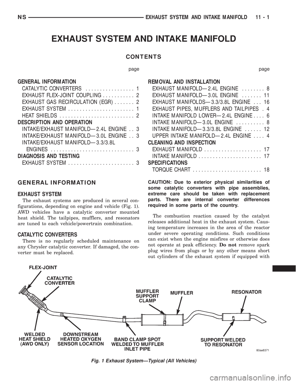
The exhaust systems are produced in several con-
figurations, depending on engine and vehicle (Fig. 1).
AWD vehicles have a catalytic converter mounted
heat shield. The tailpipes, mufflers, and resonators
are tuned to each vehicle/powertrain combination.
CATALYTIC CONVERTERS
There is no regularly scheduled maintenance on
any Chrysler catalytic converter. If damaged, the con-
verter must be replaced.CAUTION: Due to exterior physical similarities of
some catalytic converters with pipe assemblies,
extreme care should be taken with replacement
parts. There are internal converter differences
required in some parts of the country.
The combustion reaction caused by the catalyst
releases additional heat in the exhaust system. Caus-
ing temperature increases in the area of the reactor
under severe operating conditions. Such conditions
can exist when the engine misfires or otherwise does
not operate at peak efficiency.Do notremove spark
plug wires from plugs or by any other means short
out cylinders of the exhaust system if equipped with
Fig. 1 Exhaust SystemÐTypical (All Vehicles)
NSEXHAUST SYSTEM AND INTAKE MANIFOLD 11 - 1
Page 1264 of 1938
a catalytic converter. Failure of the catalytic con-
verter can occur due to temperature increases caused
by unburned fuel igniting when passing through the
converter.
The use of the catalysts also involves some non-au-
tomotive problems. Unleaded gasoline must be used
to avoid poisoning the catalyst core. Do not allow
engine to operate at fast idle for extended periods
(over 5 minutes). This condition may result in exces-
sive exhaust system and floor pan temperatures.
EXHAUST GAS RECIRCULATION (EGR)
To assist in the control of oxides of nitrogen (NOx)
in engine exhaust, all engines are equipped with an
exhaust gas recirculation system. The use of exhaust
gas to dilute incoming air/fuel mixtures lowers peak
flame temperatures during combustion, thus limiting
the formation of NOx.
Exhaust gases are taken from opening in the
exhaust manifold passage to the intake manifold.
REFER TO SECTION 25 FOR A COMPLETE
DESCRIPTION, DIAGNOSIS AND SERVICE PRO-
CEDURES ON THE EXHAUST GAS RECIRCULA-
TION SYSTEM AND COMPONENTS.
HEAT SHIELDS
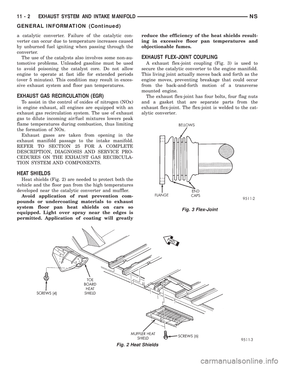
Heat shields (Fig. 2) are needed to protect both the
vehicle and the floor pan from the high temperatures
developed near the catalytic converter and muffler.
Avoid application of rust prevention com-
pounds or undercoating materials to exhaust
system floor pan heat shields on cars so
equipped. Light over spray near the edges is
permitted. Application of coating will greatlyreduce the efficiency of the heat shields result-
ing in excessive floor pan temperatures and
objectionable fumes.
EXHAUST FLEX-JOINT COUPLING
A exhaust flex-joint coupling (Fig. 3) is used to
secure the catalytic converter to the engine manifold.
This living joint actually moves back and forth as the
engine moves, preventing breakage that could occur
from the back-and-forth motion of a transverse
mounted engine.
The exhaust flex-joint has four bolts, four flag nuts
and a gasket that are separate parts from the
exhaust flex-joint. The flex-joint is welded to the cat-
alytic converter.
Fig. 2 Heat Shields
Fig. 3 Flex-Joint
11 - 2 EXHAUST SYSTEM AND INTAKE MANIFOLDNS
GENERAL INFORMATION (Continued)
Page 1265 of 1938
CAUTION: When servicing, care must be exercised
not to dent or bend the bellows of the flex-joint.
Should this occur, the flex-joint will eventually fail
and require the catalytic converter be replaced.
DESCRIPTION AND OPERATION
INTAKE/EXHAUST MANIFOLDÐ2.4L ENGINE
The intake manifold is a tuned two-piece alumi-
num casting with individual primary runners leading
from a plenum to the cylinders. The manifold is
designed to boost torque which is desired for excel-
lent engine response and usable power output.
The exhaust manifold is made of nodular cast iron
for strength and high temperatures.
INTAKE/EXHAUST MANIFOLDÐ3.0L ENGINE
The aluminum alloy manifold is a cross type with
long runners to improve air flow. The runners,
attaching below at the cylinder head, also attach
above and support an air plenum. The air plenum
chamber absorbs air pulsations created during the
suction phase of each cylinder.Both exhaust manifolds are a log style made of
ductile cast iron. Exhaust gasses, collected from the
front cylinder bank, leave the front manifold through
an end outlet and are fed through an upper crossover
tube to the rear manifold. The collected exhaust from
both manifolds are combined at the exhaust outlet, to
the exhaust pipe.
INTAKE/EXHAUST MANIFOLDÐ3.3/3.8L ENGINES
The intake manifold is a tuned two-piece semi-per-
manent mold aluminum casting with individual pri-
mary runners leading from a plenum to the
cylinders. The manifold is designed to boost torque in
the 3600 rpm range and contributes to the engine's
broad, flat torque curve, which was desired for excel-
lent engine tractability, response and usable power
output.
The intake manifold is also cored with upper level
EGR passages for balanced cylinder to cylinder EGR
distribution.
The exhaust manifolds are log type with a cross-
over and are attached directly to the cylinder heads.
They are made from nodular cast iron.
DIAGNOSIS AND TESTING
EXHAUST SYSTEM
CONDITION POSSIBLE CAUSES CORRECTION
EXCESSIVE EXHAUST
NOISE (UNDER HOOD)1. Exhaust manifold cracked or broken. 1. Replace manifold.
2. Manifold to cylinder head leak. 2. Tighten manifold and/or replace gasket.
3. EGR Valve to manifold gasket leakage. 3. Tighten fasteners or replace gasket.
4. EGR Valve to EGR tube gasket
leakage.4. Tighten fasteners or replace gasket.
5. EGR tube to manifold tube leakage. 5. Tighten tube nut.
6. Exhaust flex-joint to manifold leak. 6. Tighten joint fasteners and/or replace
gasket.
7. Exhaust flex-joint. 7. Replace catalytic converter assembly.
8. Pipe and shell noise from front exhaust
pipe.8. Characteristic of single wall pipe.
EXCESSIVE EXHAUST
NOISE1. Leak at exhaust pipe joints. 1. Tighten clamps at leaking joints.
2. Burned or rusted out muffler assembly
or exhaust pipe.2. Replace muffler resonator tailpipe
assembly or exhaust pipe with catalytic
converter assembly.
3. Burned or rusted out resonator. 3. Replace muffler resonator tailpipe
assembly.
4. Restriction in exhaust system. 4. Remove restriction, if possible, or
replace as necessary.
5. Converter material in muffler. 5. Replace muffler and converter
assemblies. Check fuel injection and
ignition systems for proper operation.
NSEXHAUST SYSTEM AND INTAKE MANIFOLD 11 - 3
GENERAL INFORMATION (Continued)
Page 1332 of 1938
system to enter into closed loop operation sooner.
Also, it allows the system to remain in closed loop
operation during periods of extended idle.
In Closed Loop operation the PCM monitors the
O2S input (along with other inputs) and adjusts the
injector pulse width accordingly. During Open Loop
operation the PCM ignores the O2 sensor input. The
PCM adjusts injector pulse width based on prepro-
grammed (fixed) values and inputs from other sen-
sors.
The Automatic Shutdown (ASD) relay supplies bat-
tery voltage to both the upstream and downstream
heated oxygen sensors. The oxygen sensors are
equipped with a heating element. The heating ele-
ments reduce the time required for the sensors to
reach operating temperature.
UPSTREAM HEATED OXYGEN SENSOR
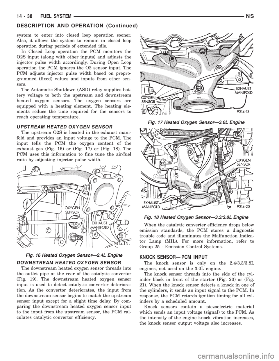
The upstream O2S is located in the exhaust mani-
fold and provides an input voltage to the PCM. The
input tells the PCM the oxygen content of the
exhaust gas (Fig. 16) or (Fig. 17) or (Fig. 18). The
PCM uses this information to fine tune the air/fuel
ratio by adjusting injector pulse width.
DOWNSTREAM HEATED OXYGEN SENSOR
The downstream heated oxygen sensor threads into
the outlet pipe at the rear of the catalytic convertor
(Fig. 19). The downstream heated oxygen sensor
input is used to detect catalytic convertor deteriora-
tion. As the convertor deteriorates, the input from
the downstream sensor begins to match the upstream
sensor input except for a slight time delay. By com-
paring the downstream heated oxygen sensor input
to the input from the upstream sensor, the PCM cal-
culates catalytic convertor efficiency.When the catalytic converter efficiency drops below
emission standards, the PCM stores a diagnostic
trouble code and illuminates the Malfunction Indica-
tor Lamp (MIL). For more information, refer to
Group 25 - Emission Control Systems.
KNOCK SENSORÐPCM INPUT
The knock sensor is only on the 2.4/3.3/3.8L
engines, not used on the 3.0L engine.
The knock sensor threads into the side of the cyl-
inder block in front of the starter (Fig. 20) or (Fig.
21). When the knock sensor detects a knock in one of
the cylinders, it sends an input signal to the PCM. In
response, the PCM retards ignition timing for all cyl-
inders by a scheduled amount.
Knock sensors contain a piezoelectric material
which sends an input voltage (signal) to the PCM. As
the intensity of the engine knock vibration increases,
the knock sensor output voltage also increases.
Fig. 16 Heated Oxygen SensorÐ2.4L Engine
Fig. 17 Heated Oxygen SensorÐ3.0L Engine
Fig. 18 Heated Oxygen SensorÐ3.3/3.8L Engine
14 - 38 FUEL SYSTEMNS
DESCRIPTION AND OPERATION (Continued)
Page 1437 of 1938
REMOVAL AND INSTALLATION
2.4 LITER POWER STEERING PUMP
REMOVE
WARNING: POWER STEERING OIL, ENGINE COM-
PONENTS AND THE EXHAUST SYSTEM MAY BE
EXTREMELY HOT IF ENGINE HAS BEEN RUNNING.
DO NOT START ENGINE WITH ANY LOOSE OR DIS-
CONNECTED HOSES. DO NOT ALLOW HOSES TO
TOUCH HOT EXHAUST MANIFOLD OR CATALYST.
(1) Remove cap from power steering fluid reser-
voir.
(2) Using a siphon pump, remove as much power
steering fluid as possible from the power steering
fluid reservoir.
(3) Remove the (-) negative battery cable from the
battery and isolate cable.
(4) Remove the drive belt from the power steering
pump pulley. See Cooling, Group 7 for detailed
removal procedure.
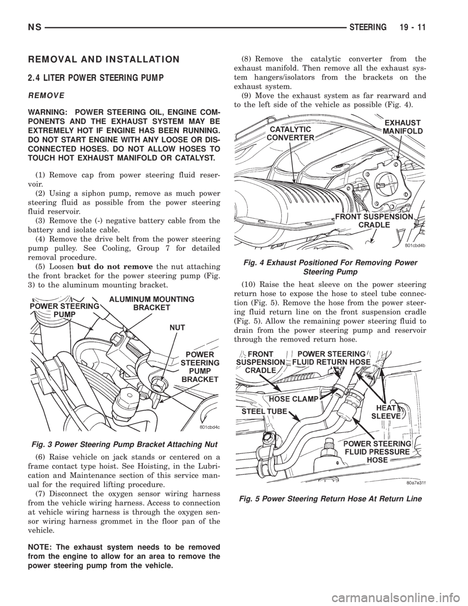
(5) Loosenbut do not removethe nut attaching
the front bracket for the power steering pump (Fig.
3) to the aluminum mounting bracket.
(6) Raise vehicle on jack stands or centered on a
frame contact type hoist. See Hoisting, in the Lubri-
cation and Maintenance section of this service man-
ual for the required lifting procedure.
(7) Disconnect the oxygen sensor wiring harness
from the vehicle wiring harness. Access to connection
at vehicle wiring harness is through the oxygen sen-
sor wiring harness grommet in the floor pan of the
vehicle.
NOTE: The exhaust system needs to be removed
from the engine to allow for an area to remove the
power steering pump from the vehicle.(8) Remove the catalytic converter from the
exhaust manifold. Then remove all the exhaust sys-
tem hangers/isolators from the brackets on the
exhaust system.
(9) Move the exhaust system as far rearward and
to the left side of the vehicle as possible (Fig. 4).
(10) Raise the heat sleeve on the power steering
return hose to expose the hose to steel tube connec-
tion (Fig. 5). Remove the hose from the power steer-
ing fluid return line on the front suspension cradle
(Fig. 5). Allow the remaining power steering fluid to
drain from the power steering pump and reservoir
through the removed return hose.
Fig. 3 Power Steering Pump Bracket Attaching Nut
Fig. 4 Exhaust Positioned For Removing Power
Steering Pump
Fig. 5 Power Steering Return Hose At Return Line
NSSTEERING 19 - 11
Page 1440 of 1938
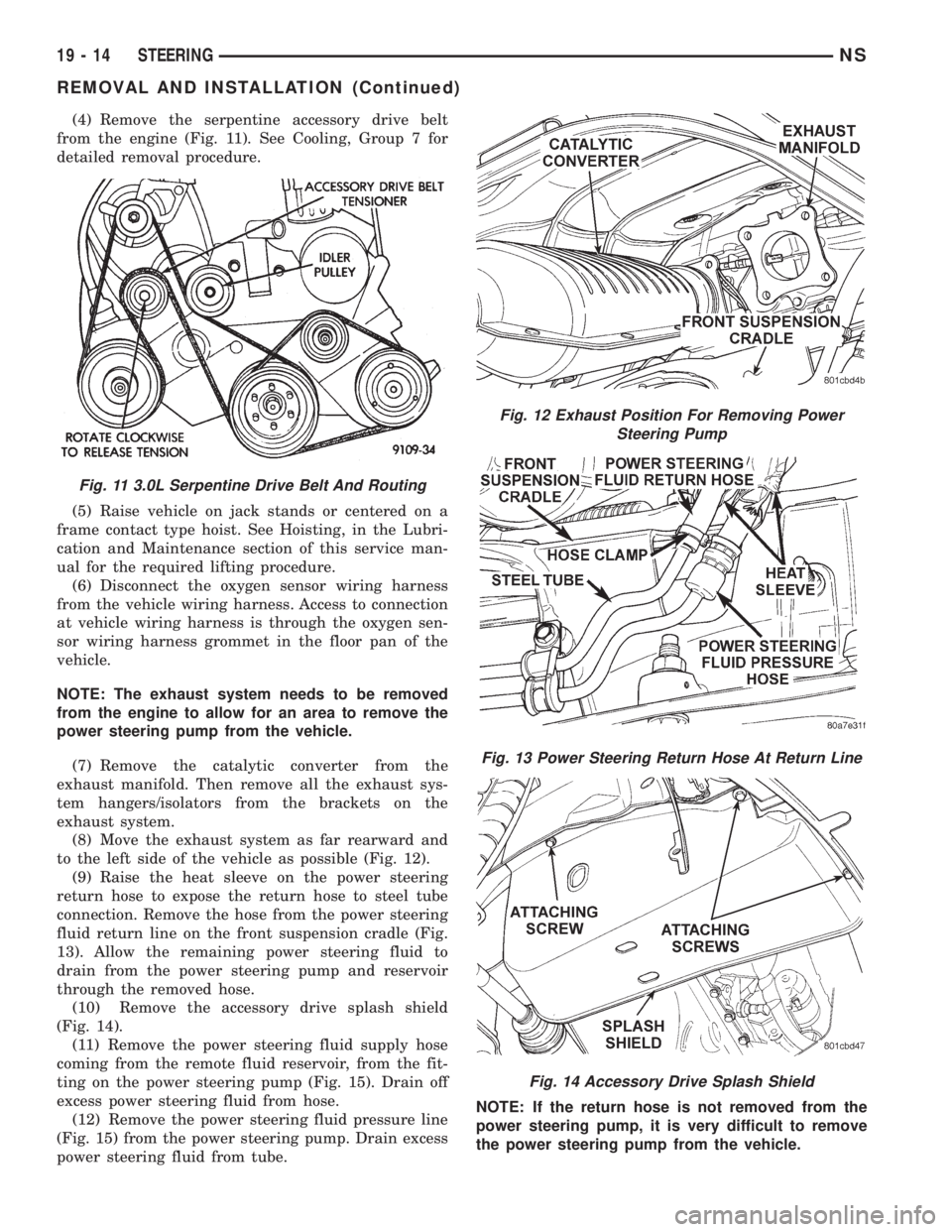
(4) Remove the serpentine accessory drive belt
from the engine (Fig. 11). See Cooling, Group 7 for
detailed removal procedure.
(5) Raise vehicle on jack stands or centered on a
frame contact type hoist. See Hoisting, in the Lubri-
cation and Maintenance section of this service man-
ual for the required lifting procedure.
(6) Disconnect the oxygen sensor wiring harness
from the vehicle wiring harness. Access to connection
at vehicle wiring harness is through the oxygen sen-
sor wiring harness grommet in the floor pan of the
vehicle.
NOTE: The exhaust system needs to be removed
from the engine to allow for an area to remove the
power steering pump from the vehicle.
(7) Remove the catalytic converter from the
exhaust manifold. Then remove all the exhaust sys-
tem hangers/isolators from the brackets on the
exhaust system.
(8) Move the exhaust system as far rearward and
to the left side of the vehicle as possible (Fig. 12).
(9) Raise the heat sleeve on the power steering
return hose to expose the return hose to steel tube
connection. Remove the hose from the power steering
fluid return line on the front suspension cradle (Fig.
13). Allow the remaining power steering fluid to
drain from the power steering pump and reservoir
through the removed hose.
(10) Remove the accessory drive splash shield
(Fig. 14).
(11) Remove the power steering fluid supply hose
coming from the remote fluid reservoir, from the fit-
ting on the power steering pump (Fig. 15). Drain off
excess power steering fluid from hose.
(12) Remove the power steering fluid pressure line
(Fig. 15) from the power steering pump. Drain excess
power steering fluid from tube.NOTE: If the return hose is not removed from the
power steering pump, it is very difficult to remove
the power steering pump from the vehicle.
Fig. 11 3.0L Serpentine Drive Belt And Routing
Fig. 12 Exhaust Position For Removing Power
Steering Pump
Fig. 13 Power Steering Return Hose At Return Line
Fig. 14 Accessory Drive Splash Shield
19 - 14 STEERINGNS
REMOVAL AND INSTALLATION (Continued)
Page 1442 of 1938
(15) Fill the remote power steering pump fluid res-
ervoir to correct fluid level.
(16) Install cap on power steering fluid reservoir.
(17) Connect the negative battery cable on the
negative battery post.
(18) Start engine and turn steering wheel several
times from stop to stop to bleed air from fluid in sys-
tem. Stop engine, check fluid level, and inspect sys-
tem for leaks. See Checking Fluid Level.
3.3/3.8 LITER POWER STEERING PUMP
REMOVE
WARNING: POWER STEERING OIL, ENGINE COM-
PONENTS AND THE EXHAUST SYSTEM MAY BE
EXTREMELY HOT IF ENGINE HAS BEEN RUNNING.
DO NOT START ENGINE WITH ANY LOOSE OR DIS-
CONNECTED HOSES. DO NOT ALLOW HOSES TO
TOUCH HOT EXHAUST MANIFOLD OR CATALYST.
(1) Remove the (-) negative battery cable from the
battery and isolate cable.
(2) Remove cap from power steering fluid reser-
voir.
(3) Using a siphon pump, remove as much power
steering fluid as possible from the power steering
fluid reservoir.
(4) Raise vehicle on jack stands or centered on a
frame contact type hoist. See Hoisting, in the Lubri-
cation and Maintenance section of this service man-
ual for the required lifting procedure.
(5) Disconnect the oxygen sensor wiring harness
from the vehicle wiring harness. Access to connection
at vehicle wiring harness is through the oxygen sen-
sor wiring harness grommet in the floor pan of the
vehicle.
NOTE: The exhaust system needs to be removed
from the engine to allow for an area to remove the
power steering pump from the vehicle.
(6) Remove the catalytic converter from the
exhaust manifold. Then remove all the exhaust sys-
tem hangers/isolators from the brackets on the
exhaust system.
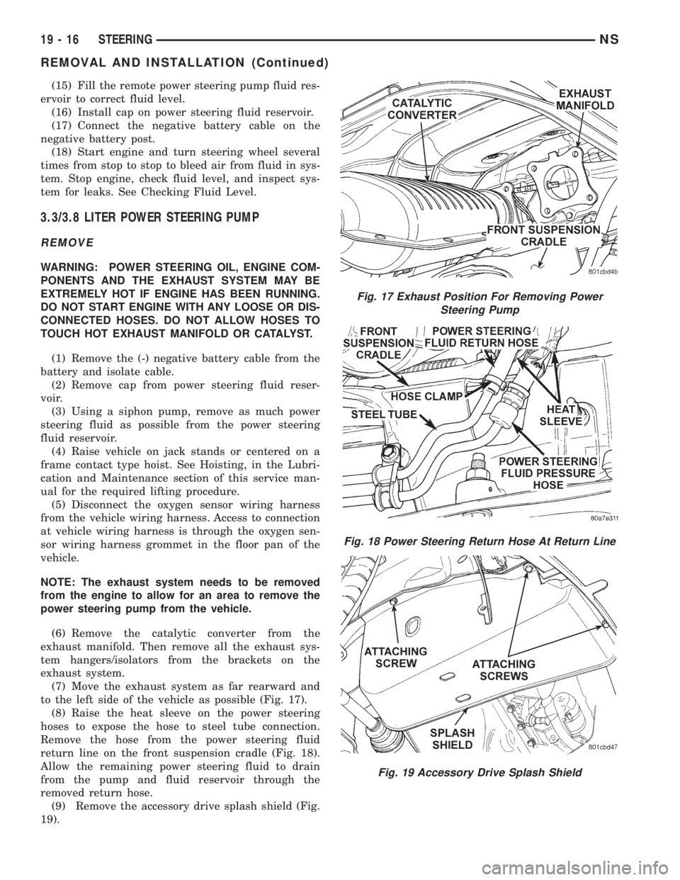
(7) Move the exhaust system as far rearward and
to the left side of the vehicle as possible (Fig. 17).
(8) Raise the heat sleeve on the power steering
hoses to expose the hose to steel tube connection.
Remove the hose from the power steering fluid
return line on the front suspension cradle (Fig. 18).
Allow the remaining power steering fluid to drain
from the pump and fluid reservoir through the
removed return hose.
(9) Remove the accessory drive splash shield (Fig.
19).
Fig. 17 Exhaust Position For Removing Power
Steering Pump
Fig. 18 Power Steering Return Hose At Return Line
Fig. 19 Accessory Drive Splash Shield
19 - 16 STEERINGNS
REMOVAL AND INSTALLATION (Continued)