1996 CHRYSLER VOYAGER oil dipstick
[x] Cancel search: oil dipstickPage 229 of 1938

WARNING: WITH TOOL IN PLACE, PRESSURE
WILL BUILD UP FAST. EXCESSIVE PRESSURE
BUILT UP, BY CONTINUOUS ENGINE OPERATION,
MUST BE RELEASED TO A SAFE PRESSURE
POINT. NEVER PERMIT PRESSURE TO EXCEED 138
kPa (20 psi).
If the needle on the dial does not fluctuate, race
the engine a few times. If an abnormal amount of
coolant or steam emits from the tail pipe, it may
indicate a coolant leak caused by a faulty head gas-
ket, cracked engine block, or cracked cylinder head.
There may be internal leaks that can be deter-
mined by removing the oil dipstick. If water globules
appear intermixed with the oil it will indicate an
internal leak in the engine. If there is an internal
leak, the engine must be disassembled for repair.
RADIATOR CAP TO FILLER NECK SEAL PRESSURE
RELIEF CHECK
The pressure cap upper gasket (seal) pressure
relief can be checked by removing the overflow hose
at the radiator filler neck nipple (Fig. 13). Attach the
Radiator Pressure Tool to the filler neck nipple and
pump air into the radiator. Pressure cap upper gas-
ket should relieve at 69-124 kPa (10-18 psi) and hold
pressure at 55 kPa (8 psi) minimum.
WARNING: THE WARNING WORDS ªDO NOT
OPEN HOTº ON THE RADIATOR PRESSURE CAP IS
A SAFETY PRECAUTION. WHEN HOT, PRESSURE
BUILDS UP IN COOLING SYSTEM. TO PREVENT
SCALDING OR INJURY, THE RADIATOR CAP
SHOULD NOT BE REMOVED WHILE THE SYSTEM
IS HOT OR UNDER PRESSURE.
There is no need to remove the radiator cap at any
timeexceptfor the following purposes:
(1) Check and adjust coolant freeze point. By add-
ing or subtracting coolant through CRS bottle.
(2) Refill system with new coolant.
(3) Conducting service procedures.
(4) Checking for vacuum leaks.WARNING: IF VEHICLE HAS BEEN RUN
RECENTLY, WAIT 15 MINUTES BEFORE REMOVING
CAP. THEN PLACE A SHOP TOWEL OVER THE CAP
AND WITHOUT PUSHING DOWN ROTATE COUN-
TERCLOCKWISE TO THE FIRST STOP. ALLOW FLU-
IDS TO ESCAPE THROUGH THE OVERFLOW TUBE
AND WHEN THE SYSTEM STOPS PUSHING COOL-
ANT AND STEAM INTO THE CRS TANK AND PRES-
SURE DROPS PUSH DOWN AND REMOVE THE CAP
COMPLETELY. SQUEEZING THE RADIATOR INLET
HOSE WITH A SHOP TOWEL (TO CHECK PRES-
SURE) BEFORE AND AFTER TURNING TO THE
FIRST STOP IS RECOMMENDED.
PRESSURE TESTING RADIATOR CAP
Dip the pressure cap in water, clean any deposits
off the vent valve or its seat and apply cap to end of
Radiator Pressure Tool. Working the plunger, bring
the pressure to 104 kPa (15 psi) on the gauge. If the
pressure cap fails to hold pressure of at least 97 kPa
(14 psi) replace cap. SeeCAUTION.
If the pressure cap tests properly while positioned
on Radiator Pressure Tool (Fig. 14), but will not hold
pressure or vacuum when positioned on the radiator.
Inspect the radiator filler neck and cap top gasket for
irregularities that may prevent the cap from sealing
properly.
CAUTION: Radiator Pressure Tool is very sensitive
to small air leaks that will not cause cooling system
problems. A pressure cap that does not have a his-
tory of coolant loss should not be replaced just
because it leaks slowly when tested with this tool.
Add water to the tool. Turn tool upside down and
recheck pressure cap to confirm that cap is bad.
LOW COOLANT LEVEL AERATION
Low coolant level in a cross flow radiator will
equalize in both tanks with engine off. With engine
Fig. 13 Radiator Pressure Cap Filler Neck
Fig. 14 Pressure Testing Radiator Cap
NSCOOLING SYSTEM 7 - 15
DIAGNOSIS AND TESTING (Continued)
Page 1055 of 1938
CAUTION: Be sure that the tapped holes maintain
the original centerline.
Heli-Coil tools and inserts are readily available
from automotive parts jobbers.
HYDROSTATIC LOCKED ENGINE
When an engine is suspected to be hydrostatically
locked, regardless of what caused the problem, these
steps should be used.
CAUTION: Do Not Use Starter Motor To Rotate
Engine, severe damage may occur.
(1) Inspect air cleaner, induction system and
intake manifold to insure system is dry and clear of
foreign material.
(2) Remove negative battery cable.
(3) Place a shop towel around the spark plugs
when removing them from the engine. This will catch
any fluid that may possibly be in the cylinder under
pressure.
(4) With all spark plugs removed, rotate engine
crankshaft using a breaker bar and socket.
(5) Identify the fluid in the cylinder(s) (i.e., cool-
ant, fuel, oil or other).
(6) Make sure all fluid has been removed from the
cylinders. Inspect engine for damage (i.e., Connecting
Rods, Pistons, Valves etc.)
(7) Repair engine or components as necessary to
prevent this problem from occurring again.
CAUTION: Squirt approximately 1 teaspoon of oil
into cylinders, rotate engine to lubricate the cylin-
der walls to prevent damage on restart.
(8) Install new spark plugs.
(9) Drain engine oil and remove oil filter.
(10) Fill engine with specified amount of approved
oil and install new oil filter.
(11) Connect negative battery cable.
(12) Start engine and check for any leaks.
ENGINE OIL
Checking Oil Level
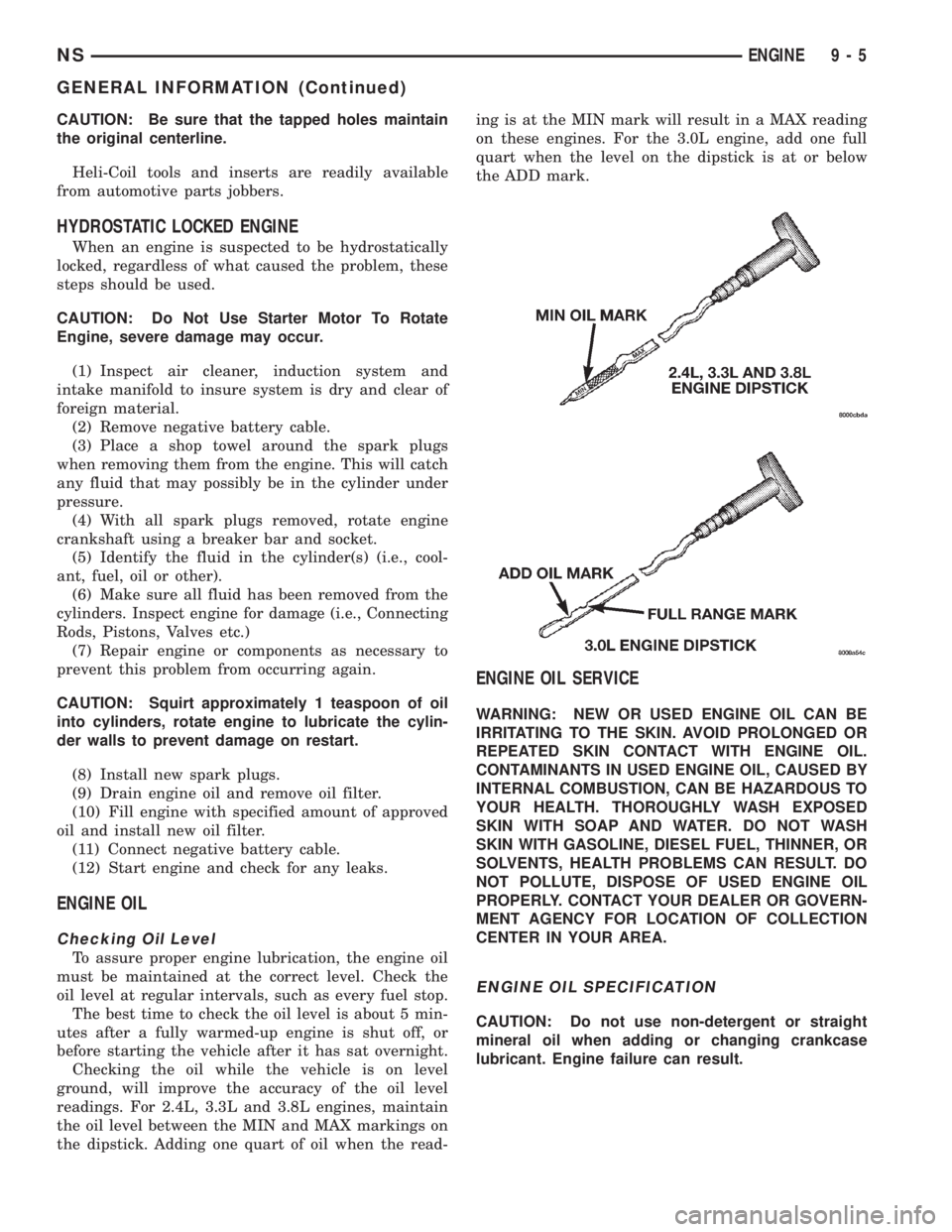
To assure proper engine lubrication, the engine oil
must be maintained at the correct level. Check the
oil level at regular intervals, such as every fuel stop.
The best time to check the oil level is about 5 min-
utes after a fully warmed-up engine is shut off, or
before starting the vehicle after it has sat overnight.
Checking the oil while the vehicle is on level
ground, will improve the accuracy of the oil level
readings. For 2.4L, 3.3L and 3.8L engines, maintain
the oil level between the MIN and MAX markings on
the dipstick. Adding one quart of oil when the read-ing is at the MIN mark will result in a MAX reading
on these engines. For the 3.0L engine, add one full
quart when the level on the dipstick is at or below
the ADD mark.
ENGINE OIL SERVICE
WARNING: NEW OR USED ENGINE OIL CAN BE
IRRITATING TO THE SKIN. AVOID PROLONGED OR
REPEATED SKIN CONTACT WITH ENGINE OIL.
CONTAMINANTS IN USED ENGINE OIL, CAUSED BY
INTERNAL COMBUSTION, CAN BE HAZARDOUS TO
YOUR HEALTH. THOROUGHLY WASH EXPOSED
SKIN WITH SOAP AND WATER. DO NOT WASH
SKIN WITH GASOLINE, DIESEL FUEL, THINNER, OR
SOLVENTS, HEALTH PROBLEMS CAN RESULT. DO
NOT POLLUTE, DISPOSE OF USED ENGINE OIL
PROPERLY. CONTACT YOUR DEALER OR GOVERN-
MENT AGENCY FOR LOCATION OF COLLECTION
CENTER IN YOUR AREA.
ENGINE OIL SPECIFICATION
CAUTION: Do not use non-detergent or straight
mineral oil when adding or changing crankcase
lubricant. Engine failure can result.
NSENGINE 9 - 5
GENERAL INFORMATION (Continued)
Page 1059 of 1938
(2) Add an oil soluble dye (use as recommended by
manufacturer). Start the engine and let idle for
approximately 15 minutes. Check the oil dipstick to
make sure the dye is thoroughly mixed as indicated
with a bright yellow color under a black light.
(3) Using a black light, inspect the entire engine
for fluorescent dye, particularly at the suspected area
of oil leak. If the oil leak is found and identified,
repair per service manual instructions.
(4) If dye is not observed, drive the vehicle at var-
ious speeds for approximately 24km (15 miles), and
repeat inspection.
(5)If the oil leak source is not positively
identified at this time, proceed with the air leak
detection test method as follows:
(6) Disconnect the fresh air hose (makeup air) at
the cylinder head cover and plug or cap the nipple on
the cover.
(7) Remove the PCV valve hose from the cylinder
head cover. Cap or plug the PCV valve nipple on the
cover.
(8) Attach an air hose with pressure gauge and
regulator to the dipstick tube.
CAUTION: Do not subject the engine assembly to
more than 20.6 kpa (3 PSI) of test pressure.
(9) Gradually apply air pressure from 1 psi to 2.5
psi maximum while applying soapy water at the sus-
pected source. Adjust the regulator to the suitable
test pressure that provide the best bubbles which
will pinpoint the leak source. If the oil leak is
detected and identified, repair per service manual
procedures.
(10) If the leakage occurs at the rear oil seal area,
refer to the section, Inspection for Rear Seal Area
Leak.
(11) If no leaks are detected, turn off the air sup-
ply and remove the air hose and all plugs and caps.
Install the PCV valve and breather cap hose. Proceed
to next step.
(12) Clean the oil off the suspect oil leak area
using a suitable solvent. Drive the vehicle at various
speeds approximately 24 km (15 miles). Inspect the
engine for signs of an oil leak by using a black light.INSPECTION FOR REAR SEAL AREA LEAKS
Since it is sometimes difficult to determine the
source of an oil leak in the rear seal area of the
engine, a more involved inspection is necessary. The
following steps should be followed to help pinpoint
the source of the leak.
If the leakage occurs at the crankshaft rear oil seal
area:
(1) Disconnect the battery.
(2) Raise the vehicle.
(3) Remove torque converter or clutch housing
cover and inspect rear of block for evidence of oil.
Use a black light to check for the oil leak. If a leak is
present in this area remove transmission for further
inspection.
(a) Circular spray pattern generally indicates
seal leakage or crankshaft damage.
(b) Where leakage tends to run straight down,
possible causes are a porous block, oil galley cup
plug, bedplate to cylinder block mating surfaces
and seal bore. See proper repair procedures for
these items.
(4) If no leaks are detected, pressurized the crank-
case as outlined in the, Inspection (Engine oil Leaks
in general)
CAUTION: Do not exceed 20.6 kPa (3 psi).
(5) If the leak is not detected, very slowly turn the
crankshaft and watch for leakage. If a leak is
detected between the crankshaft and seal while
slowly turning the crankshaft, it is possible the
crankshaft seal surface is damaged. The seal area on
the crankshaft could have minor nicks or scratches
that can be polished out with emery cloth.
CAUTION: Use extreme caution when crankshaft
polishing is necessary to remove minor nicks and
scratches. The crankshaft seal flange is especially
machined to complement the function of the rear oil
seal.
(6) For bubbles that remain steady with shaft
rotation, no further inspection can be done until dis-
assembled.
(7) After the oil leak root cause and appropriate
corrective action have been identified. Refer to Rear
Crankshaft Seals, for proper replacement procedures.
NSENGINE 9 - 9
DIAGNOSIS AND TESTING (Continued)
Page 1120 of 1938
(25) Remove ground straps to body.
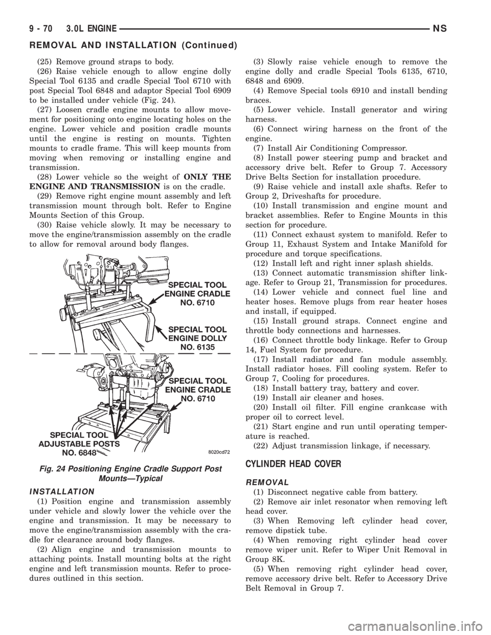
(26) Raise vehicle enough to allow engine dolly
Special Tool 6135 and cradle Special Tool 6710 with
post Special Tool 6848 and adaptor Special Tool 6909
to be installed under vehicle (Fig. 24).
(27) Loosen cradle engine mounts to allow move-
ment for positioning onto engine locating holes on the
engine. Lower vehicle and position cradle mounts
until the engine is resting on mounts. Tighten
mounts to cradle frame. This will keep mounts from
moving when removing or installing engine and
transmission.
(28) Lower vehicle so the weight ofONLY THE
ENGINE AND TRANSMISSIONis on the cradle.
(29) Remove right engine mount assembly and left
transmission mount through bolt. Refer to Engine
Mounts Section of this Group.
(30) Raise vehicle slowly. It may be necessary to
move the engine/transmission assembly on the cradle
to allow for removal around body flanges.
INSTALLATION
(1) Position engine and transmission assembly
under vehicle and slowly lower the vehicle over the
engine and transmission. It may be necessary to
move the engine/transmission assembly with the cra-
dle for clearance around body flanges.
(2) Align engine and transmission mounts to
attaching points. Install mounting bolts at the right
engine and left transmission mounts. Refer to proce-
dures outlined in this section.(3) Slowly raise vehicle enough to remove the
engine dolly and cradle Special Tools 6135, 6710,
6848 and 6909.
(4) Remove Special tools 6910 and install bending
braces.
(5) Lower vehicle. Install generator and wiring
harness.
(6) Connect wiring harness on the front of the
engine.
(7) Install Air Conditioning Compressor.
(8) Install power steering pump and bracket and
accessory drive belt. Refer to Group 7. Accessory
Drive Belts Section for installation procedure.
(9) Raise vehicle and install axle shafts. Refer to
Group 2, Driveshafts for procedure.
(10) Install transmission and engine mount and
bracket assemblies. Refer to Engine Mounts in this
section for procedure.
(11) Connect exhaust system to manifold. Refer to
Group 11, Exhaust System and Intake Manifold for
procedure and torque specifications.
(12) Install left and right inner splash shields.
(13) Connect automatic transmission shifter link-
age. Refer to Group 21, Transmission for procedures.
(14) Lower vehicle and connect fuel line and
heater hoses. Remove plugs from rear heater hoses
and install, if equipped.
(15) Install ground straps. Connect engine and
throttle body connections and harnesses.
(16) Connect throttle body linkage. Refer to Group
14, Fuel System for procedure.
(17) Install radiator and fan module assembly.
Install radiator hoses. Fill cooling system. Refer to
Group 7, Cooling for procedures.
(18) Install battery tray, battery and cover.
(19) Install air cleaner and hoses.
(20) Install oil filter. Fill engine crankcase with
proper oil to correct level.
(21) Start engine and run until operating temper-
ature is reached.
(22) Adjust transmission linkage, if necessary.
CYLINDER HEAD COVER
REMOVAL
(1) Disconnect negative cable from battery.
(2) Remove air inlet resonator when removing left
head cover.
(3) When Removing left cylinder head cover,
remove dipstick tube.
(4) When removing right cylinder head cover
remove wiper unit. Refer to Wiper Unit Removal in
Group 8K.
(5) When removing right cylinder head cover,
remove accessory drive belt. Refer to Accessory Drive
Belt Removal in Group 7.
Fig. 24 Positioning Engine Cradle Support Post
MountsÐTypical
9 - 70 3.0L ENGINENS
REMOVAL AND INSTALLATION (Continued)
Page 1145 of 1938
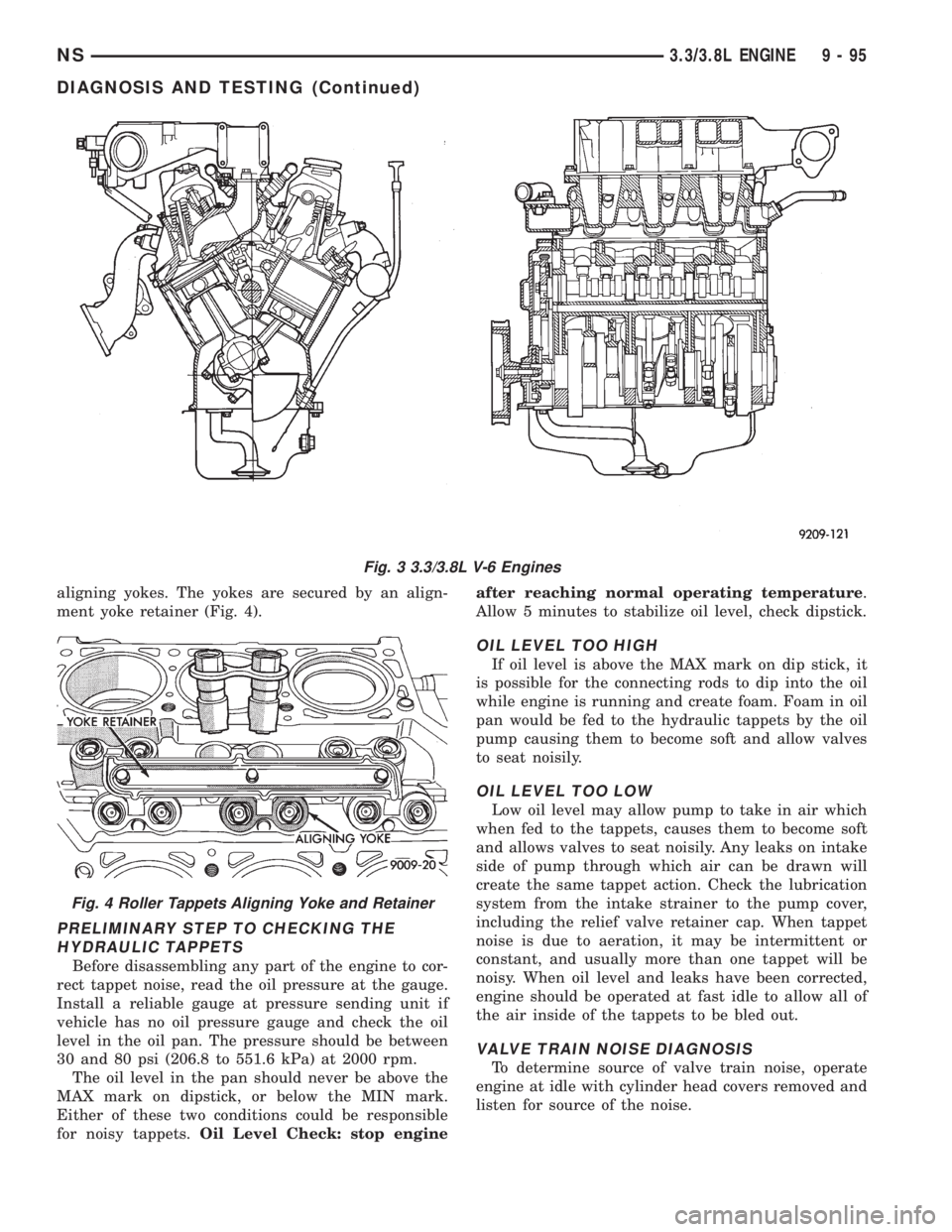
aligning yokes. The yokes are secured by an align-
ment yoke retainer (Fig. 4).
PRELIMINARY STEP TO CHECKING THE
HYDRAULIC TAPPETS
Before disassembling any part of the engine to cor-
rect tappet noise, read the oil pressure at the gauge.
Install a reliable gauge at pressure sending unit if
vehicle has no oil pressure gauge and check the oil
level in the oil pan. The pressure should be between
30 and 80 psi (206.8 to 551.6 kPa) at 2000 rpm.
The oil level in the pan should never be above the
MAX mark on dipstick, or below the MIN mark.
Either of these two conditions could be responsible
for noisy tappets.Oil Level Check: stop engineafter reaching normal operating temperature.
Allow 5 minutes to stabilize oil level, check dipstick.
OIL LEVEL TOO HIGH
If oil level is above the MAX mark on dip stick, it
is possible for the connecting rods to dip into the oil
while engine is running and create foam. Foam in oil
pan would be fed to the hydraulic tappets by the oil
pump causing them to become soft and allow valves
to seat noisily.
OIL LEVEL TOO LOW
Low oil level may allow pump to take in air which
when fed to the tappets, causes them to become soft
and allows valves to seat noisily. Any leaks on intake
side of pump through which air can be drawn will
create the same tappet action. Check the lubrication
system from the intake strainer to the pump cover,
including the relief valve retainer cap. When tappet
noise is due to aeration, it may be intermittent or
constant, and usually more than one tappet will be
noisy. When oil level and leaks have been corrected,
engine should be operated at fast idle to allow all of
the air inside of the tappets to be bled out.
VALVE TRAIN NOISE DIAGNOSIS
To determine source of valve train noise, operate
engine at idle with cylinder head covers removed and
listen for source of the noise.
Fig. 3 3.3/3.8L V-6 Engines
Fig. 4 Roller Tappets Aligning Yoke and Retainer
NS3.3/3.8L ENGINE 9 - 95
DIAGNOSIS AND TESTING (Continued)
Page 1164 of 1938
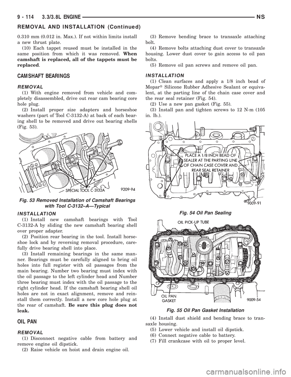
0.310 mm (0.012 in. Max.). If not within limits install
a new thrust plate.
(10) Each tappet reused must be installed in the
same position from which it was removed.When
camshaft is replaced, all of the tappets must be
replaced.
CAMSHAFT BEARINGS
REMOVAL
(1) With engine removed from vehicle and com-
pletely disassembled, drive out rear cam bearing core
hole plug.
(2) Install proper size adapters and horseshoe
washers (part of Tool C-3132-A) at back of each bear-
ing shell to be removed and drive out bearing shells
(Fig. 53).
INSTALLATION
(1) Install new camshaft bearings with Tool
C-3132-A by sliding the new camshaft bearing shell
over proper adapter.
(2) Position rear bearing in the tool. Install horse-
shoe lock and by reversing removal procedure, care-
fully drive bearing shell into place.
(3) Install remaining bearings in the same man-
ner. Bearings must be carefully aligned to bring oil
holes into full register with oil passages from the
main bearing. Number two bearing must index with
the oil passage to the left cylinder head and Number
three bearing must index with the oil passage to the
right cylinder head. If the camshaft bearing shell oil
holes are not in exact alignment, remove and rein-
stall them correctly. Install a new core hole plug at
the rear of camshaft.Be sure this plug does not
leak.
OIL PAN
REMOVAL
(1) Disconnect negative cable from battery and
remove engine oil dipstick.
(2) Raise vehicle on hoist and drain engine oil.(3) Remove bending brace to transaxle attaching
bolt.
(4) Remove bolts attaching dust cover to transaxle
housing. Lower dust cover to gain access to oil pan
bolts.
(5) Remove oil pan screws and remove oil pan.
INSTALLATION
(1) Clean surfaces and apply a 1/8 inch bead of
MopartSilicone Rubber Adhesive Sealant or equiva-
lent, at the parting line of the chain case cover and
the rear seal retainer (Fig. 54).
(2) Use a new pan gasket (Fig. 55).
(3) Install pan and tighten screws to 12 N´m (105
in. lb.).
(4) Install dust shield and bending brace to tran-
saxle housing.
(5) Lower vehicle and install oil dipstick.
(6) Connect negative cable to battery.
(7) Fill crankcase with oil to proper level.
Fig. 53 Removed Installation of Camshaft Bearings
with Tool C-3132±AÐTypical
Fig. 54 Oil Pan Sealing
Fig. 55 Oil Pan Gasket Installation
9 - 114 3.3/3.8L ENGINENS
REMOVAL AND INSTALLATION (Continued)
Page 1222 of 1938
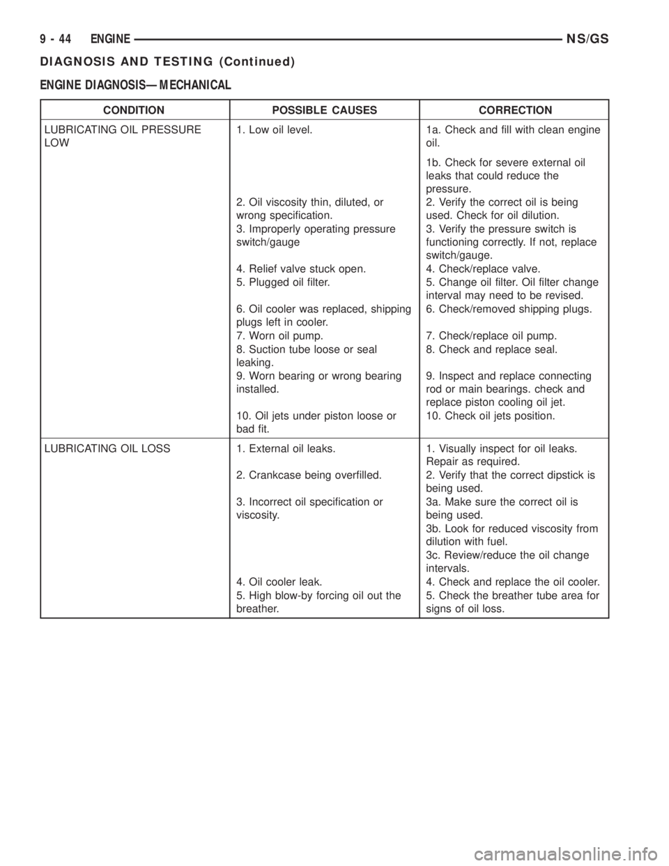
ENGINE DIAGNOSISÐMECHANICAL
CONDITION POSSIBLE CAUSES CORRECTION
LUBRICATING OIL PRESSURE
LOW1. Low oil level. 1a. Check and fill with clean engine
oil.
1b. Check for severe external oil
leaks that could reduce the
pressure.
2. Oil viscosity thin, diluted, or
wrong specification.2. Verify the correct oil is being
used. Check for oil dilution.
3. Improperly operating pressure
switch/gauge3. Verify the pressure switch is
functioning correctly. If not, replace
switch/gauge.
4. Relief valve stuck open. 4. Check/replace valve.
5. Plugged oil filter. 5. Change oil filter. Oil filter change
interval may need to be revised.
6. Oil cooler was replaced, shipping
plugs left in cooler.6. Check/removed shipping plugs.
7. Worn oil pump. 7. Check/replace oil pump.
8. Suction tube loose or seal
leaking.8. Check and replace seal.
9. Worn bearing or wrong bearing
installed.9. Inspect and replace connecting
rod or main bearings. check and
replace piston cooling oil jet.
10. Oil jets under piston loose or
bad fit.10. Check oil jets position.
LUBRICATING OIL LOSS 1. External oil leaks. 1. Visually inspect for oil leaks.
Repair as required.
2. Crankcase being overfilled. 2. Verify that the correct dipstick is
being used.
3. Incorrect oil specification or
viscosity.3a. Make sure the correct oil is
being used.
3b. Look for reduced viscosity from
dilution with fuel.
3c. Review/reduce the oil change
intervals.
4. Oil cooler leak. 4. Check and replace the oil cooler.
5. High blow-by forcing oil out the
breather.5. Check the breather tube area for
signs of oil loss.
9 - 44 ENGINENS/GS
DIAGNOSIS AND TESTING (Continued)
Page 1225 of 1938
HYDRAULIC TAPPETS
Before disassembling any part of the engine to cor-
rect tappet noise, check the oil pressure. If vehicle
has no oil pressure gauge, install a reliable gauge at
the pressure sending unit. The pressure should be
between 3.5 bars to 5.0 bars at 4000 RPM.
Check the oil level after the engine reaches normal
operating temperature. Allow 5 minutes to stabilize
oil level, check dipstick. The oil level in the pan
should never be above the FULL mark or below the
ADD OIL mark on dipstick. Either of these 2 condi-
tions could be responsible for noisy tappets.
OIL LEVEL HIGH
If oil level is above the FULL mark, it is possible
for the connecting rods to dip into the oil. With the
engine running, this condition could create foam in
the oil pan. Foam in oil pan would be fed to the
hydraulic tappets by the oil pump causing them to
lose length and allow valves to seat noisily.
OIL LEVEL LOW
Low oil level may allow oil pump to take in air.
When air is fed to the tappets, they lose length which
allows valves to seat noisily. Any leaks on intake side
of oil pump through which air can be drawn will cre-
ate the same tappet action. Check the lubrication
system from the intake strainer to the pump cover,
including the relief valve retainer cap. When tappet
noise is due to aeration, it may be intermittent or
constant, and usually more than 1 tappet will be
noisy. When oil level and leaks have been corrected,
operate the engine at fast idle. Run engine for a suf-
ficient time to allow all of the air inside the tappets
to be bled out.
TAPPET NOISE DIAGNOSIS
(1) To determine source of tappet noise, operate
engine at idle with cylinder head covers removed.
(2) Feel each valve spring or rocker arm to detect
noisy tappet. The noisy tappet will cause the affected
spring and/or rocker arm to vibrate or feel rough in
operation.
NOTE: Worn valve guides or cocked springs are
sometimes mistaken for noisy tappets. If such is
the case, noise may be dampened by applying side
thrust on the valve spring. If noise is not apprecia-
bly reduced, it can be assumed the noise is in the
tappet. Inspect the rocker arm push rod sockets
and push rod ends for wear.
(3) Valve tappet noise ranges from light noise to a
heavy click. A light noise is usually caused by exces-
sive leak down around the unit plunger or by the
plunger partially sticking in the tappet body cylinder.
The tappet should be replaced. A heavy click iscaused by a tappet check valve not seating or by for-
eign particles becoming wedged between the plunger
and the tappet body. This will cause the plunger to
stick in the down position. This heavy click will be
accompanied by excessive clearance between the
valve stem and rocker arm as valve closes. In either
case, tappet assembly should be removed for inspec-
tion and cleaning.
(4) The valve train generates a noise very much
like a light tappet noise during normal operation.
Care must be taken to ensure that tappets are mak-
ing the noise. In general, if more than one tappet
seems to be noisy, its probably not the tappets.
SERVICE PROCEDURES
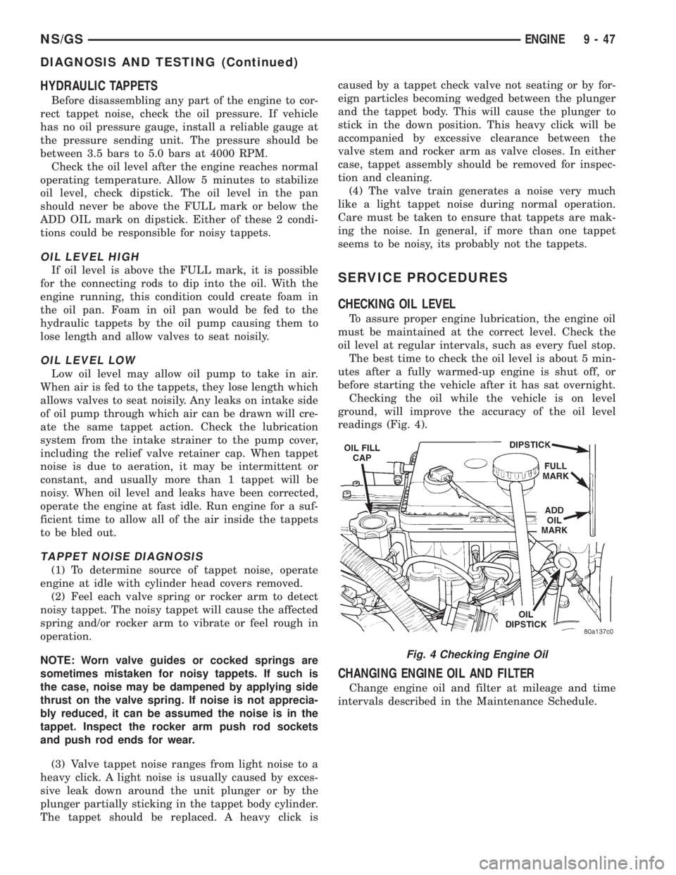
CHECKING OIL LEVEL
To assure proper engine lubrication, the engine oil
must be maintained at the correct level. Check the
oil level at regular intervals, such as every fuel stop.
The best time to check the oil level is about 5 min-
utes after a fully warmed-up engine is shut off, or
before starting the vehicle after it has sat overnight.
Checking the oil while the vehicle is on level
ground, will improve the accuracy of the oil level
readings (Fig. 4).
CHANGING ENGINE OIL AND FILTER
Change engine oil and filter at mileage and time
intervals described in the Maintenance Schedule.
Fig. 4 Checking Engine Oil
NS/GSENGINE 9 - 47
DIAGNOSIS AND TESTING (Continued)