1996 CHRYSLER VOYAGER coolant reservoir
[x] Cancel search: coolant reservoirPage 19 of 1938

MAINTENANCE SCHEDULES
INDEX
page page
GENERAL INFORMATION
INTRODUCTION......................... 3
SCHEDULE ± A.......................... 3SCHEDULE ± B.......................... 4
UNSCHEDULED INSPECTION............... 3
GENERAL INFORMATION
INTRODUCTION
Service and maintenance procedures for compo-
nents and systems listed in Schedule ± A or B can be
found by using the Group Tab Locator index at the
front of this manual. If it is not clear which group
contains the information needed, refer to the index at
the back of this manual.
There are two maintenance schedules that show
proper service based on the conditions that the vehi-
cle is subjected to.
Schedule ±A, lists scheduled maintenance to be
performed when the vehicle is used for general trans-
portation.
Schedule ±B, lists maintenance intervals for vehi-
cles that are operated under the conditions listed at
the beginning of the Maintenance Schedule section.
Use the schedule that best describes your driving
conditions.
Where time and mileage are listed, follow the
interval that occurs first.
UNSCHEDULED INSPECTION
At Each Stop for Fuel
²Check engine oil level, add as required.
²Check windshield washer solvent and add if
required.
Once a Month
²Check tire pressure and look for unusual wear
or damage.
²Inspect battery and clean and tighten terminals
as required.
²Check fluid levels of coolant reservoir, brake
master cylinder, power steering and transaxle and
add as needed.
²Check all lights and all other electrical items for
correct operation.
²Check rubber seals on each side of the radiator
for proper fit.
At Each Oil Change
²Inspect exhaust system.
²Inspect brake hoses
²Inspect the CV joints and front suspension com-
ponents
²Rotate the tires at each oil change interval
shown on Schedule ± A (7,500 miles) or every other
interval shown on Schedule ± B (6,000 miles).
²Check the coolant level, hoses, and clamps.
²If your mileage is less than 7,500 miles (12 000
km) yearly, replace the engine oil filter at each oil
change.
²Replace engine oil filter on 2.4L engines.
SCHEDULE ± A
7,500 Miles (12 000 km) or at 6 months
²Change engine oil.
15,000 Miles (24 000 km) or at 12 months
²Change engine oil.
²Replace engine oil filter.
22,500 Miles (36 000 km) or at 18 months
²Change engine oil.
²Inspect brake linings.
30,000 Miles (48 000 km) or at 24 months
²Change engine oil.
²Change automatic transmission fluid.
²Replace engine oil filter.
²Replace air cleaner element.
²Inspect tie rod ends and boot seals.
37,500 Miles (60 000 km) or at 30 months
²Change engine oil.
45,000 Miles (72 000 km) or at 36 months
²Change engine oil.
²Replace engine oil filter.
²Inspect brake linings.
²Flush and replace engine coolant at 36 months,
regardless of mileage.
NSLUBRICATION AND MAINTENANCE 0 - 3
Page 28 of 1938

MAINTENANCE SCHEDULES
INDEX
page page
GENERAL INFORMATION
MAINTENANCE SCHEDULE............... 2
MAINTENANCE SCHEDULEÐ
DIESEL ENGINE....................... 2SCHEDULEÐA (DIESEL).................. 2
SCHEDULEÐB (DIESEL).................. 3
UNSCHEDULED INSPECTION.............. 2
GENERAL INFORMATION
MAINTENANCE SCHEDULE
Refer to the 1998 GS Service Manual for Gasoline
Engine and non-engine related Maintenance Sched-
ules.
MAINTENANCE SCHEDULEÐDIESEL ENGINE
The following are engine related Maintenance
items which are unique to Diesel engine-equipped
vehicles. Refer to the 1998 GS Service Manual for
Gasoline Engine and non-engine related Maintenance
Schedules.
The service intervals are based on odometer read-
ings in kilometers. There are two maintenance sched-
ules that show proper service intervals. Use the
schedule that best describes the conditions the vehi-
cle is operated under.Schedule-Alists all the sched-
uled maintenance to be performed under normal
operating conditions.Schedule-Bis the schedule for
vehicles that are operated under one or more of the
following conditions:
²Day and night temperatures are below freezing.
²Stop and go driving.
²Long periods of engine idling.
²Driving in dusty conditions.
²Short trips of less than 5 miles.
²Operation at sustained high speeds during hot
weather above 32ÉC (90ÉF).
²Taxi, police or delivery service.
²Trailer towing.
UNSCHEDULED INSPECTION
At Each Stop for Fuel
²Check engine oil level, add as required.
²Check windshield washer solvent and add if
required.
Once a Month
²Check tire pressure and look for unusual wear
or damage.
²Inspect battery and clean and tighten terminals
as required.²Check fluid levels of coolant reservoir, brake
master cylinder, power steering and transaxle and
add as needed.
²Check all lights and all other electrical items for
correct operation.
²Check rubber seals on each side of the radiator
for proper fit.
At Each Oil Change
²Inspect exhaust system.
²Inspect brake hoses
²Inspect the CV joints and front suspension com-
ponents
²Rotate the tires at each oil change interval
shown on ScheduleÐA (7,500 miles) or every other
interval shown on ScheduleÐ B (6,000 miles).
²Check the coolant level, hoses, and clamps.
²If your mileage is less than 7,500 miles (12 000
km) yearly, replace the engine oil filter at each oil
change.
²Replace engine oil filter.
SCHEDULEÐA (DIESEL)
1 000 KM
²Change engine oil.
²Change engine oil filter.
²Check all fluid levels.
²Check correct torque, intake manifold mounting
nuts.
²Check correct torque, exhaust manifold mount-
ing nuts.
²Check correct torque, turbocharger mounting
nuts.
²Check correct torque, water manifold bolts.
10 000 KM
²Change engine oil.
²Change engine oil filter.
20 000 KM
²Change engine oil.
²Change engine oil filter.
²Replace air filter element.
0 - 2 LUBRICATION AND MAINTENANCENS/GS
Page 249 of 1938

(2) Install water pump pulley.
(3) Install drive belt, Refer to Accessory Drive
Belts, this Group. Tighten water pump pulley attach-
ing bolts to 27.5 N´m (240 in. lbs.)
(4) Install right inner splash shield.
(5) Refill cooling system. Refer to Refilling Cooling
System in this Group.
ENGINE THERMOSTATÐ 2.0L GASOLINE
REMOVAL
(1) Drain cooling system to the thermostat level or
below.
(2) Remove coolant recovery system (CRS) hose
and thermostat/engine outlet connector bolts.
(3) Remove thermostat and seal, and clean sealing
surfaces.
INSTALLATION
(1) Place the new thermostat assembly into the
thermostat housing/outlet connector. Align air bleed
vent with notch in cylinder head.
(2) Install thermostat housing/outlet connector
onto cylinder head and tighten bolts to 12.5 N´m (110
in. lbs.). Connect the upper radiator hose.
(3) Refill cooling system (seeRefilling System).
THERMOSTAT Ð 2.5L VM DIESEL
REMOVAL
(1) Drain cooling system down below the thermo-
stat level. Refer to Draining Cooling System in this
section.(2) Remove radiator hose at thermostat cover.
(3) Remove thermostat cover bolts (Fig. 20).
(4) Remove Thermostat.
INSTALLATION
(1) Remove old gasket material from thermostat
housing and cover.
(2) Install new thermostat gasket.
(3) Install thermostat and tighten cover bolts to
10.8 N´m (96 in. lbs.).
(4) Install radiator hose.
(5) Refill cooling system. Refer to Refilling Cooling
System in this section.
RADIATOR Ð 2.5L VM DIESEL
REMOVAL
(1) Disconnect battery.
(2) Remove power steering reservoir attaching
bolts, and reposition reservoir.
(3) Remove radiator closure panel crossmember
(Fig. 21).
(4) Remove air cleaner housing and intake hose.
(5) Unplug fan module 4 pin wiring connector.
(6) Drain cooling system. Refer to Draining cooling
system in this section for procedure.
(7) Remove upper and lower Radiator Hoses.
(8) Remove radiator attaching bolts.
(9) Loosen A/C receiver/dryer lower bolt.
(10) Remove Radiator.
(11) Remove fan module from radiator.
Fig. 19 Water Pump Drive BeltÐ 2.5 L VM Diesel
Fig. 20 Thermostat and Housing Ð 2.5L VM Diesel
NS/GSCOOLING SYSTEM 7 - 9
REMOVAL AND INSTALLATION (Continued)
Page 1231 of 1938

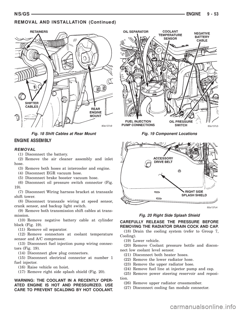
ENGINE ASSEMBLY
REMOVAL
(1) Disconnect the battery.
(2) Remove the air cleaner assembly and inlet
hose.
(3) Remove both hoses at intercooler and engine.
(4) Disconnect EGR vacuum hose.
(5) Disconnect brake booster vacuum hose.
(6) Disconnect oil pressure switch connector (Fig.
19).
(7) Disconnect Wiring harness bracket at transaxle
shift tower.
(8) Disconnect transaxle wiring at speed sensor,
crank sensor, and backup light switch.
(9) Remove both transmission shift cables at trans-
mission.
(10) Remove negative battery cable at cylinder
block (Fig. 19).
(11) Remove oil separator.
(12) Remove connectors at coolant temperature
sensor and A/C compressor.
(13) Disconnect fuel injection pump wiring connec-
tors (Fig. 19).
(14) Disconnect glow plug connectors.
(15) Disconnect electrical connector at number 1
fuel injector.
(16) Raise vehicle on hoist.
(17) Remove right side splash shield (Fig. 20).
WARNING: THE COOLANT IN A RECENTLY OPER-
ATED ENGINE IS HOT AND PRESSURIZED. USE
CARE TO PREVENT SCALDING BY HOT COOLANT.CAREFULLY RELEASE THE PRESSURE BEFORE
REMOVING THE RADIATOR DRAIN COCK AND CAP.
(18) Drain the cooling system (refer to Group 7,
Cooling).
(19) Lower vehicle.
(20) Remove Coolant pressure bottle and discon-
nect low coolant level sensor.
(21) Disconnect both heater hoses.
(22) Remove the lower radiator hose.
(23) Remove the upper radiator hose.
(24) Remove fuel line at injector pump and cap.
(25) Remove power steering reservoir and reposi-
tion.
(26) Remove upper radiator crossmember.
(27) Disconnect cooling fan module connector.
Fig. 18 Shift Cables at Rear MountFig. 19 Component Locations
Fig. 20 Right Side Splash Shield
NS/GSENGINE 9 - 53
REMOVAL AND INSTALLATION (Continued)
Page 1668 of 1938

DIFFERENTIAL BEARING RETAINER AXLE
SEAL
REMOVAL
(1) Remove axle shaft. Refer to Group 2, Suspen-
sion and Driveshafts for service procedures.
(2) Insert a flat±blade pry tool into the axle seal
bore.
(3) Using the pry tool, carefully pop out the seal
taking care not to nick the seal bore.
INSTALLATION
(1) Clean axle shaft seal bore of any excess seal-
ant.
(2) Align axle shaft seal with axle shaft seal bore.
(3) Position axle seal at extension housing.
(4) Using Tool L-4520 and Tool C-4171, tap seal
into position.
SHIFT SHAFT SEALS
It isnotnecessary to remove the shift shaft cover
from the transaxle to service the shift shaft seals.
REMOVAL
(1) Remove the shift lever from the seal that is to
be serviced. Refer to shift lever removal for service
procedure.
(2) Using a pick tool, pry up on the shift shaft seal
and remove seal from bore.
INSTALLATION
(1) Position new shift shaft seal in bore.
(2) Install shift shaft seal into bore using an
appropriate size deep±well socket.
TRANSAXLE
The following items can be serviced without remov-
ing the transaxle from the vehicle:
²Gearshift housing
²5th speed synchronizer
²5th speed gear
²Roller detents and springs
²Speedometer pinion
²Vehicle speed sensor
²Bearing retainer plate.
²All external covers
²Shift shaft seals
²Axle shaft seals
To service any other component of the A-598 tran-
saxle you must remove it from the vehicle.
REMOVAL
(1) Disconnect battery negative cable.
(2) Remove air intake hose. Disconnect air mass
meter connector.
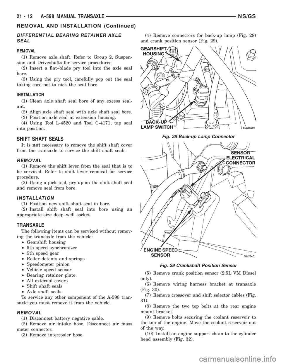
(3) Remove intercooler hose.(4) Remove connectors for back-up lamp (Fig. 28)
and crank position sensor (Fig. 29).
(5) Remove crank position sensor (2.5L VM Diesel
only).
(6) Remove wiring harness bracket at transaxle
(Fig. 30).
(7) Remove crossover and shift selector cables (Fig.
31).
(8) Remove the two top bolts at the rear engine
mount bracket.
(9) Remove bolts securing the coolant reservoir to
the top of the engine. Move the coolant reservoir out
of the way.
(10) Install an engine support chain to the cylinder
head assembly (Fig. 32).
Fig. 28 Back-up Lamp Connector
Fig. 29 Crankshaft Position Sensor
21 - 12 A±598 MANUAL TRANSAXLENS/GS
REMOVAL AND INSTALLATION (Continued)