Page 1670 of 1938
(25) Install transmission jack under transaxle
assembly.
(26) Remove left fender splash shield.
(27) Remove (4) left mount bolts (Fig. 42).(28) Remove lower bellhousing bolts.
(29) Lower transaxle and remove.
INSTALLATION
(1) For installation, reverse removal procedure.
NOTE: Lower control arm pinch bolts must be
installed with the bolt heads to the rear of the ball
joints.
(2) Fill transaxle to the proper level with the spec-
ified lubricant.
(3) While the vehicle is elevated slightly, run the
transaxle through all the forward gears. Apply
brakes and shift into reverse. Run the transaxle
through reverse gear.
Fig. 35 Lower Control Arm Pinch Bolt
Fig. 36 Unseat Control Arm
Fig. 37 Transaxle Drain Plug
Fig. 38 Vehicle Speed Sensor
Fig. 39 Clutch Cable Clip
21 - 14 A±598 MANUAL TRANSAXLENS/GS
REMOVAL AND INSTALLATION (Continued)
Page 1675 of 1938

(22) Remove lower starter bolt.
(23) Remove engine wiring harness clip.
CAUTION: Always use a safety chain when remov-
ing or installing transaxle assembly.
(24) Place a transmission jack under the transmis-
sion
(25) Remove the transaxle lower dust cover.
(26) Remove the access cover in right splash shield
to access torsional damper bolt.
(27) Remove drive plate to modular clutch bolts
while holding torsional damper bolt with socket and
ratchet. To avoid distortion of the drive plate, remove
the modular clutch bolts a few turns at a time. Use a
crisscross pattern until all bolts are loosened.
(28) Unbolt rear engine mount through bolt and
two (2) mount bolts.
(29) Remove the left front fender splash shield.
(30) Unbolt left engine mount through bolt and
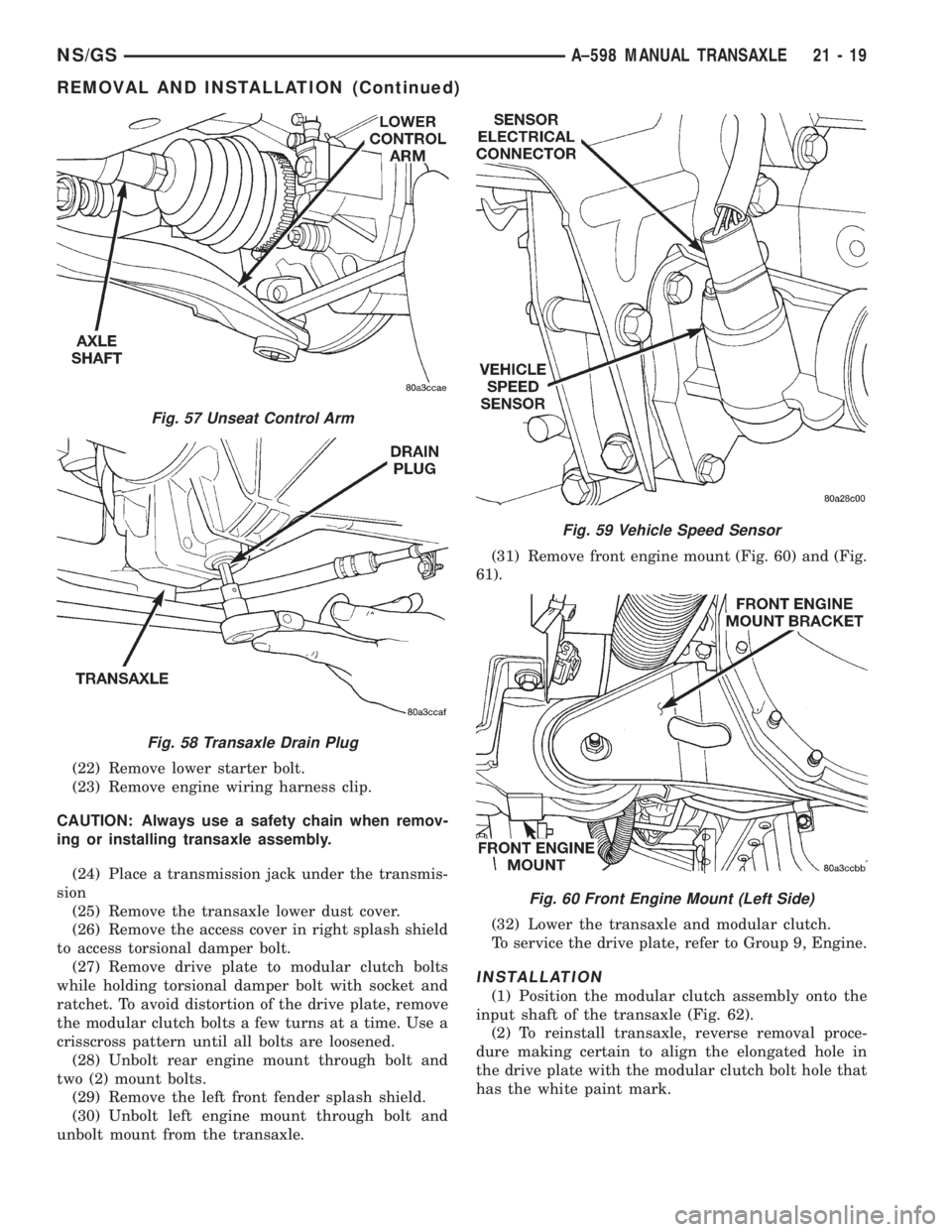
unbolt mount from the transaxle.(31) Remove front engine mount (Fig. 60) and (Fig.
61).
(32) Lower the transaxle and modular clutch.
To service the drive plate, refer to Group 9, Engine.
INSTALLATION
(1) Position the modular clutch assembly onto the
input shaft of the transaxle (Fig. 62).
(2) To reinstall transaxle, reverse removal proce-
dure making certain to align the elongated hole in
the drive plate with the modular clutch bolt hole that
has the white paint mark.
Fig. 57 Unseat Control Arm
Fig. 58 Transaxle Drain Plug
Fig. 59 Vehicle Speed Sensor
Fig. 60 Front Engine Mount (Left Side)
NS/GSA±598 MANUAL TRANSAXLE 21 - 19
REMOVAL AND INSTALLATION (Continued)
Page 1910 of 1938

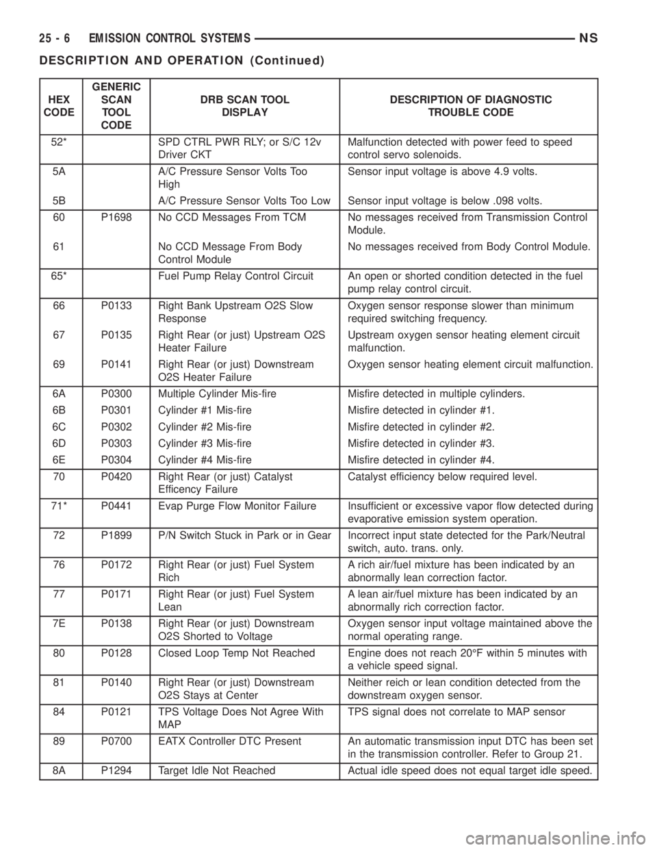
HEX
CODEGENERIC
SCAN
TOOL
CODEDRB SCAN TOOL
DISPLAYDESCRIPTION OF DIAGNOSTIC
TROUBLE CODE
52* SPD CTRL PWR RLY; or S/C 12v
Driver CKTMalfunction detected with power feed to speed
control servo solenoids.
5A A/C Pressure Sensor Volts Too
HighSensor input voltage is above 4.9 volts.
5B A/C Pressure Sensor Volts Too Low Sensor input voltage is below .098 volts.
60 P1698 No CCD Messages From TCM No messages received from Transmission Control
Module.
61 No CCD Message From Body
Control ModuleNo messages received from Body Control Module.
65* Fuel Pump Relay Control Circuit An open or shorted condition detected in the fuel
pump relay control circuit.
66 P0133 Right Bank Upstream O2S Slow
ResponseOxygen sensor response slower than minimum
required switching frequency.
67 P0135 Right Rear (or just) Upstream O2S
Heater FailureUpstream oxygen sensor heating element circuit
malfunction.
69 P0141 Right Rear (or just) Downstream
O2S Heater FailureOxygen sensor heating element circuit malfunction.
6A P0300 Multiple Cylinder Mis-fire Misfire detected in multiple cylinders.
6B P0301 Cylinder #1 Mis-fire Misfire detected in cylinder #1.
6C P0302 Cylinder #2 Mis-fire Misfire detected in cylinder #2.
6D P0303 Cylinder #3 Mis-fire Misfire detected in cylinder #3.
6E P0304 Cylinder #4 Mis-fire Misfire detected in cylinder #4.
70 P0420 Right Rear (or just) Catalyst
Efficency FailureCatalyst efficiency below required level.
71* P0441 Evap Purge Flow Monitor Failure Insufficient or excessive vapor flow detected during
evaporative emission system operation.
72 P1899 P/N Switch Stuck in Park or in Gear Incorrect input state detected for the Park/Neutral
switch, auto. trans. only.
76 P0172 Right Rear (or just) Fuel System
RichA rich air/fuel mixture has been indicated by an
abnormally lean correction factor.
77 P0171 Right Rear (or just) Fuel System
LeanA lean air/fuel mixture has been indicated by an
abnormally rich correction factor.
7E P0138 Right Rear (or just) Downstream
O2S Shorted to VoltageOxygen sensor input voltage maintained above the
normal operating range.
80 P0128 Closed Loop Temp Not Reached Engine does not reach 20ÉF within 5 minutes with
a vehicle speed signal.
81 P0140 Right Rear (or just) Downstream
O2S Stays at CenterNeither reich or lean condition detected from the
downstream oxygen sensor.
84 P0121 TPS Voltage Does Not Agree With
MAPTPS signal does not correlate to MAP sensor
89 P0700 EATX Controller DTC Present An automatic transmission input DTC has been set
in the transmission controller. Refer to Group 21.
8A P1294 Target Idle Not Reached Actual idle speed does not equal target idle speed.
25 - 6 EMISSION CONTROL SYSTEMSNS
DESCRIPTION AND OPERATION (Continued)