1996 CHRYSLER VOYAGER interior lights
[x] Cancel search: interior lightsPage 255 of 1938

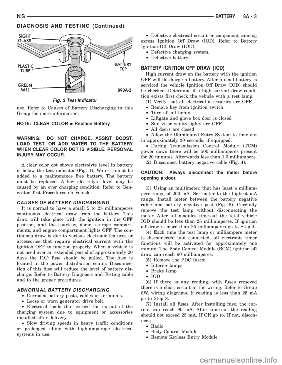
use. Refer to Causes of Battery Discharging in this
Group for more information.
NOTE: CLEAR COLOR = Replace Battery
WARNING: DO NOT CHARGE, ASSIST BOOST,
LOAD TEST, OR ADD WATER TO THE BATTERY
WHEN CLEAR COLOR DOT IS VISIBLE. PERSONAL
INJURY MAY OCCUR.
A clear color dot shows electrolyte level in battery
is below the test indicator (Fig. 1). Water cannot be
added to a maintenance free battery. The battery
must be replaced. A low electrolyte level may be
caused by an over charging condition. Refer to Gen-
erator Test Procedures on Vehicle.
CAUSES OF BATTERY DISCHARGING
It is normal to have a small 5 to 25 milliamperes
continuous electrical draw from the battery. This
draw will take place with the ignition in the OFF
position, and the courtesy, dome, storage compart-
ments, and engine compartment lights OFF. The con-
tinuous draw is due to various electronic features or
accessories that require electrical current with the
ignition OFF to function properly. When a vehicle is
not used over an extended period of approximately 20
days the IOD fuse should be pulled. The fuse is
located in the power distribution center. Disconnec-
tion of this fuse will reduce the level of battery dis-
charge. Refer to Battery Diagnosis and Testing table
and to the proper procedures.
ABNORMAL BATTERY DISCHARGING
²Corroded battery posts, cables or terminals.
²Loose or worn generator drive belt.
²Electrical loads that exceed the output of the
charging system due to equipment or accessories
installed after delivery.
²Slow driving speeds in heavy traffic conditions
or prolonged idling with high-amperage electrical
systems in use.²Defective electrical circuit or component causing
excess Ignition Off Draw (IOD). Refer to Battery
Ignition Off Draw (IOD).
²Defective charging system.
²Defective battery.
BATTERY IGNITION OFF DRAW (IOD)
High current draw on the battery with the ignition
OFF will discharge a battery. After a dead battery is
serviced the vehicle Ignition Off Draw (IOD) should
be checked. Determine if a high current draw condi-
tion exists first check the vehicle with a test lamp.
(1) Verify that all electrical accessories are OFF.
²Remove key from ignition switch
²Turn off all lights
²Liftgate and glove box door is closed
²Sun visor vanity lights are OFF
²All doors are closed
²Allow the Illuminated Entry System to time out
in approximately 30 seconds, if equipped.
²During Transmission Control Module (TCM)
power down there will be 500 milliamperes present
for 20 minutes. Afterwards less than 1.0 milliampere.
(2) Disconnect battery negative cable (Fig. 4).
CAUTION: Always disconnect the meter before
opening a door.
(3) Using an multimeter, that has least a milliam-
pere range of 200 mA. Set meter to the highest mA
range. Install meter between the battery negative
cable and battery negative post (Fig. 5). Carefully
remove the test lamp without disconnecting the
meter. After all modules time-out the total vehicle
IOD should be less than 25 milliamperes. If ignition
off draw is more than 25 milliamperes go to Step 4.
(4) Each time the test lamp or milliampere meter
is disconnected and connected, all electronic timer
functions will be activated for approximately one
minute. The Body Control Module (BCM) ignition off
draw can reach 90 milliamperes.
(5) Remove the PDC fuses:
²Interior lamps
²Brake lamp
²IOD
(6) If there is any reading, with fuses removed
there is a short circuit in the wiring. Refer to Group
8W, wiring diagrams. If reading is less than 25 mA
go to Step 8.
(7) Install all fuses. After installing fuse, the cur-
rent can reach 90 mA. After time-out the reading
should not exceed 25 mA. If OK go to. If not, discon-
nect:
²Radio
²Body Control Module
²Remote Keyless Entry Module
Fig. 3 Test Indicator
NSBATTERY 8A - 3
DIAGNOSIS AND TESTING (Continued)
Page 495 of 1938

BULB APPLICATION
INDEX
page page
GENERAL INFORMATION
INTRODUCTION....................... 17
CLEANING AND INSPECTION
HEADLAMP CLEANING.................. 17SPECIFICATIONS
EXTERIOR LAMP BULBS................. 17
INTERIOR LAMP BULBS................. 17
GENERAL INFORMATION
INTRODUCTION
The following Bulb Application Tables list the lamp
title on the left side of the column and trade number
or part number on the right.
CAUTION: Do not use bulbs that have a higher
candle power than the bulb listed in the Bulb Appli-
cation Table. Damage to lamp can result.
Do not touch halogen bulbs with fingers or other
possibly oily surfaces. Bulb life will be reduced.
If a halogen bulb is contaminated with oil, clean
bulb with denatured alcohol or ammonia based sol-
vent.
CLEANING AND INSPECTION
HEADLAMP CLEANING
This vehicle is equipped with plastic headlights
that are lighter and less susceptible to stone break-
age than glass headlights.
This plastic is not as scratch resistant as glass and
therefore a different lens cleaning procedures must
be followed.
To minimize the possibility of scratching the lenses
and reducing light output, avoid wiping with a dry
cloth. To remove road dirt, wash with a mild soap
solution followed by rinsing with water.
Do not use abrasive cleaning components, solvents,
steel wool or other aggressive material to clean the
lenses.
SPECIFICATIONS
EXTERIOR LAMP BULBS
LAMP BULB
Back-up.............................P21W
CHMSL (Non-Solar Tint)................P21W
CHMSL (Solar Tint)....................R10WLAMP BULB
Fog Lamp..............................H3
Headlamp..............................H4
License Plate..........................C5W
Front Turn Signal....................PY21W
Citylight..............................T4W
Front Side Repeater.....................T4W
Tail, Stop...........................P21/5W
Rear Turn Signal......................P21W
Rear Fog Lamp........................P21W
INTERIOR LAMP BULBS
LAMP BULB
ABS ................................PC194
AirBag .............................PC194
Alarm Set (Security/Immobilzer)..........PC194
Brake Warning.......................PC194
Center/Rear Reading Lamps...............578
Center/Rear Dome Lamps.................579
Cruise Indicator.......................PC194
Door Ajar Indicator....................PC194
Engine Compartment Lamps...............579
Engine Temp Indicator.................PC194
Front Door Courtesy......................567
Glove Box Lamp.........................194
Glow Plug Indicator (Diesel Engine Only) . . . PC194
High Beam Indicator...................PC194
Instrument Cluster....................PC194
IP/Ash Tray (Left Hand Drive Only).........161
Liftgate Flood Lamps.....................567
Liftgate Ajar Indicator...................PC74
Low Coolant Level (Diesel Engine Only).....PC74
Low Fuel Indicator....................PC194
Low Volts Warning.....................PC74
Low Washer Fluid......................PC74
Oil Pressure Indicator..................PC194
O/H Console Reading Lamps...............579
Seat Belt Indicator (Except Diesel).........PC74
Service Engine Soon...................PC194
Turn Signal..........................PC194
Visor Vanity Lamp...................6501966
NS/GSLAMPS 8L - 17