1996 CHRYSLER VOYAGER transmission
[x] Cancel search: transmissionPage 1076 of 1938
ENGINE ASSEMBLY
REMOVAL
(1) Perform fuel pressure release procedure. Refer
to Group 14, Fuel System for procedure. Remove fuel
line to fuel rail.
(2) Disconnect battery.
(3) Remove Air cleaner and hoses.
(4) Drain cooling system. Refer to Group 7, Cooling
System for procedure.
(5) Remove upper radiator hose and remove radia-
tor fans. Refer to Group 7, Cooling System for proce-
dure.
(6) Remove lower radiator hose.
(7) Disconnect automatic transmission cooler lines
and plug, if equipped.
(8) Disconnect transmission shift linkage.
(9) Disconnect throttle body linkage.
(10) Disconnect engine wiring harness.
(11) Disconnect heater hoses.
(12) Discharge Air Conditioning System. Refer to
Group 24, Air Conditioning for procedure.
(13) Hoist vehicle and remove right inner splash
shield. Remove wheels and tires.
(14) Loosen power steering belt for pump removal.
Refer to Group 7, Cooling System for procedure.
(15) Remove axle shafts. Refer to Group 2, Suspen-
sion and Driveshafts for procedure.
(16) Disconnect exhaust pipe from manifold.
(17) Remove front and rear engine mount brackets
from the body.
(18) Remove bending braces and front engine
mount bracket. Remove transmission inspection
cover.
(19) Mark flexplate to torque converter and
remove torque converter bolts.
(20) Install front engine mount bracket.
(21) Lower vehicle.
(22) Remove power steering pump. Set pump
aside.
(23) Remove A/C lines at compressor and cap.
(24) Remove ground straps to body.
(25) Raise vehicle enough to allow engine dolly
Special Tool 6135, cradle Special Tool 6710 with
Posts Special Tool 6848 and Adaptor Special Tool
8130 to be installed under vehicle (Fig. 27).
(26) Loosen cradle posts to allow movement for
proper positioning. Locate two rear posts (right side
of engine) into the holes on the engine bedplate.
Locate the two front posts (left side of engine) on the
front engine bracket and A/C compressor bracket
(Fig. 27). Lower vehicle and position cradle mounts
until the engine is resting on mounts. Tighten
mounts to cradle frame. This will keep mounts from
moving when removing or installing engine and
transmission.(27) Lower vehicle so the weight ofONLY THE
ENGINE AND TRANSMISSIONare on the cradle.
(28) Remove engine and transmission mount bolts.
(29) Raise vehicle slowly. It may be necessary to
move the engine/transmission assembly on the cradle
to allow for removal around the body.
INSTALLATION
(1) Position engine and transmission assembly
under vehicle and slowly lower the vehicle over the
engine and transmission.
(2) Align engine and transmission mounts to
attaching points. Install mounting bolts at the right
engine and left transmission mounts. Refer to proce-
dures outlined in this section.
(3) Slowly raise vehicle enough to remove the
engine dolly and cradle Special Tools 6135 and 6710.
(4) Install axle shafts. Refer to Group 2, Suspen-
sion and Driveshafts for procedure.
(5) Install transmission and engine braces and
splash shields.
(6) Connect exhaust system to manifold. Refer to
Group 11, Exhaust System and Intake Manifold for
procedure and torque specifications.
(7) Install power steering pump. Refer to Cooling
System Group 7, Accessory Drive Section for belt ten-
sion adjustment.
(8) Install A/C compressor hoses. Refer to Group
24, Heater and Air Conditioning for procedure.
(9) Install accessory drive belts. Refer to Group 7,
Cooling System Accessory Drive Section for belt ten-
sion adjustment.
(10) Install front and rear engine mounts. Refer to
this section for procedure.
(11) Install inner splash shield. Install wheels and
tires.
(12) Connect automatic transmission cooler lines,
and shift linkage. Refer to Group 21, Transmission
for procedures.
(13) Connect fuel line and heater hoses.
(14) Install ground straps. Connect engine and
throttle body connections and harnesses. Refer to
Group 8, Electrical for procedure.
(15) Connect throttle body linkage. Refer to Group
14, Fuel System for procedure.
(16) Install radiator fans. Install radiator hoses.
Fill cooling system. Refer to Group 7, Cooling System
for filling procedure.
(17) Connect battery.
(18) Install air cleaner and hoses.
(19) Install oil filter. Fill engine crankcase with
proper oil to correct level.
(20) Start engine and run until operating temper-
ature is reached.
(21) Adjust transmission linkage, if necessary.
9 - 26 2.4L ENGINENS
REMOVAL AND INSTALLATION (Continued)
Page 1104 of 1938
CYLINDER BLOCK
(1) Clean cylinder block thoroughly and check all
core hole plugs for evidence of leaking.
(2) If new core plugs are installed, refer to Engine
Core Plugs outlined in this section.
(3) Examine block and cylinder bores for cracks or
fractures.
CYLINDER BORE INSPECTION
The cylinder walls should be checked for out-of-
round and taper with Tool C119 (Fig. 107). The cyl-
inder bore out-of-round is 0.050 mm (0.002 in.)
maximum and cylinder bore taper is 0.051 mm (0.002
in.) maximum. If the cylinder walls are badly scuffed
or scored, the cylinder block should be replaced, and
new pistons and rings fitted.
Measure the cylinder bore at three levels in direc-
tions A and B (Fig. 107). Top measurement should be
10 mm (3/8 in.) down and bottom measurement
should be 10 mm (3/8 in.) up from bottom of bore.
Refer to Cylinder Bore and Piston Specification
Chart.
ADJUSTMENTS
ENGINE MOUNTS
ENGINE MOUNT INSULATOR ADJUSTMENT
(1) Remove the load on the engine motor mounts
by carefully supporting the engine and transmission
assembly with a floor jack.
(2) Loosen the right engine mount insulator verti-
cal fastener and the fore and aft fasteners, and the
front engine mount bracket to front crossmember
screws.
(3) Pry the engine right or left as required to
achieve the proper drive shaft assembly length. Refer
to Group 2, Suspension and Driveshafts for drive-
shaft identification and related assembly length mea-
suring.
(4) Tighten engine mounts and fasteners in the
following order:
(a) Right engine mount insulator vertical bolts
to 102 N´m (75 ft. lbs.) and the fore and aft bolts to
150 N´m (110 ft. lbs.).
(b) Front engine mount screws to 54 N´m (40 ft.
lbs.) the clearance between the snubbers and the
engine should be 2 mm (0.078 inch.) each side.
(c) Left engine mount through bolt to 75 N´m (55
ft. lbs.).
(5) Recheck driveshaft length.
Fig. 107 Checking Cylinder Bore Size
CYLINDER BORE AND PISTON
SPECIFICATION CHART
Standard Bore Maximum Out-
Of-RoundMaximum-
Taper
87.5 mm 0.051 mm 0.051 mm
(3.445 in.) (0.002 in.) (0.002 in.)
Standard Piston Size
87.450 - 87.468 mm (3.4434 - 3.4441 in.)
Piston To Bore Clearance
0.024 - 0.057 mm (0.0009 - 0.0022 in.)
Measurements taken at Piston Size Location.
9 - 54 2.4L ENGINENS
CLEANING AND INSPECTION (Continued)
Page 1118 of 1938
REMOVAL AND INSTALLATION
ENGINE MOUNTS
RIGHT SIDE MOUNT
REMOVAL
NOTE: Right mount should only be serviced as an
assembly to prevent noise, vibration and harshness
concerns.
(1) Remove the purge duty solenoid and wiring
harness from engine mount.
(2) Remove the two right engine mount insulator
vertical fasteners and loosen the horizontal fastener.
Do Not remove the large nut on the end of the
core from the frame rail (Fig. 20).
(3) Remove the load on the engine motor mounts
by carefully supporting the engine and transmission
assembly with a floor jack.
(4) Remove the vertical and horizontal fasteners
from the engine side bracket. Remove the engine
mount assembly
INSTALLATION
(1) Reverse removal procedure for installation.
Tighten assembly in the following order:
(a) Engine mount to rail fasteners to 68 N´m (50
ft. lbs.).
(b) The vertical engine fastener to 102 N´m (75
ft. lbs.).
(c) The horizontal fastener to 150 N´m (111 ft.
lbs.).
(2) Install the purge duty solenoid and wiring har-
ness to the engine mount.
(3) Engine mount adjustment, Refer to Engine
Mount Insulator Adjustment.
FRONT MOUNT
REMOVAL
(1) Support the engine and transmission assembly
with a floor jack so it will not rotate.
(2) Remove the front engine mount through bolt
from the insulator and front crossmember mounting
bracket (Fig. 21).
(3) Remove six screws from air dam to allow
access to the front mount screws.
(4) Remove the front engine mount screws and
remove the insulator assembly.
(5) Remove the front mounting bracket, if neces-
sary (Fig. 21).
INSTALLATION
(1) Reverse removal procedure for installation and
tighten fasteners in this order:
(a) Tighten bolts 2, 3, and 4 to 108 N´m (80 ft.
lbs.).
(b) Tighten bolts 1 and 5 to 54 N´m (40 ft. lbs.).
(2) Engine mount adjustment. Refer to Engine
Mount Insulator Adjustment of this section.
(3) Install six screws to air dam and tighten to 12
N´m (105 in. lbs.).
LEFT SIDE MOUNT
REMOVAL
(1) Raise vehicle on hoist and remove left front
wheel.
(2) Support the transmission with a transmission
jack.
(3) Remove the insulator through bolt from the
mount.
(4) Remove the transmission mount fasteners and
remove mount.
INSTALLATION
(1) Reverse removal procedure for installation.
Fig. 20 Engine MountÐRight
Fig. 21 Engine MountÐFront
9 - 68 3.0L ENGINENS
Page 1119 of 1938
(2) Tighten mount to transmission bolts to 55 N´m
(40 ft. lbs.) (Fig. 22).
Tighten through bolt to 75 N´m (55 ft. lbs.)
(3) Engine mount adjustment, Refer to Engine
Mount Insulator Adjustment of this section.
REAR MOUNT
(1) Raise vehicle on hoist.
(2) Support the transmission with a transmission
jack so it will not rotate.
(3) Remove the insulator through bolt from the
mount and rear suspension crossmember.
(4) Remove the four transmission mount fasteners
and remove the mount.
(5) Reverse the removal procedure for installation.
Refer to (Fig. 23).
ENGINE MOUNT RUBBER INSULATORS
Insulator location on (right side) is adjustable to
allow right/left drive train adjustment in relation to
driveshaft assembly length. See Engine Mount
Adjustments in this section.
Check and reposition right engine mount insulator.
Adjust drive train position, if required, for the follow-
ing conditions:
²Driveshaft distress: See Group 2, Suspension
and Driveshafts.
²Any front end structural damage (after repair).
²Insulator replacement.
ENGINE ASSEMBLY
REMOVAL
(1) Perform fuel pressure release procedure. Refer
to Group 14, Fuel System for procedure. Remove fuel
line to fuel rail.
(2) Disconnect battery.
(3) Remove Air cleaner and hoses.
(4) Remove battery cover, battery and battery tray,
with integral vacuum reservoir, from vehicle.
(5) Block off heater hoses to rear heater assembly,
if equipped.
(6) Drain cooling system. Refer to Group 7, Cooling
System for procedure.
(7) Disconnect heater hoses.
(8) Remove fan module and radiator. Refer to
Group 7, Cooling System for procedure.
(9) Disconnect transmission shift linkage.
(10) Disconnect throttle body linkage and vacuum
hoses from throttle body.
(11) Remove accessory drive belts. Refer to Acces-
sory Drive System located in Group 7, Cooling Sys-
tem for procedure.
(12) Remove air conditioning compressor from
engine and set it aside.
(13) Disconnect generator wiring harness and
remove generator.
(14) Hoist vehicle and remove axle shafts. Refer to
Group 2, Driveshaft for procedure.
(15) Remove right and left inner splash shields.
(16) Disconnect exhaust pipe from manifold.
(17) Remove front engine mount and bracket as an
assembly.
(18) Remove rear transmission mount and bracket.
(19) Remove power steering pump and bracket
assembly.
(20) Remove wiring harness and connectors from
front of engine.
(21) Remove bending braces and install tool num-
ber 6910 on engine.
(22) Remove trans inspection cover and mark flex-
plate to torque converter.
(23) Remove driveplate to torque converter bolts.
(24) Lower the vehicle.
Fig. 22 Engine MountÐLeft
Fig. 23 Engine MountÐRear
NS3.0L ENGINE 9 - 69
REMOVAL AND INSTALLATION (Continued)
Page 1120 of 1938
(25) Remove ground straps to body.
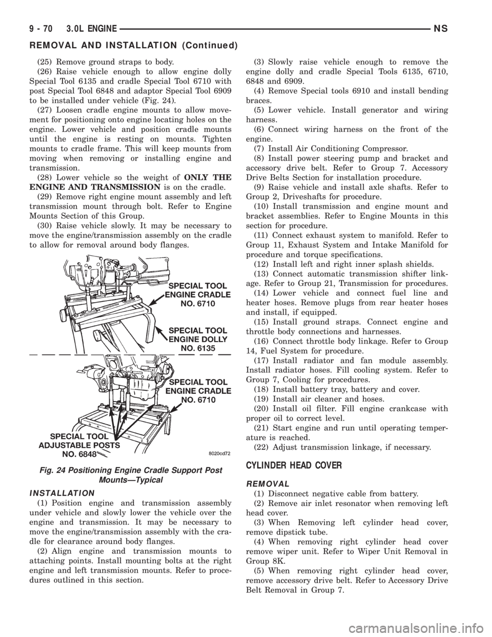
(26) Raise vehicle enough to allow engine dolly
Special Tool 6135 and cradle Special Tool 6710 with
post Special Tool 6848 and adaptor Special Tool 6909
to be installed under vehicle (Fig. 24).
(27) Loosen cradle engine mounts to allow move-
ment for positioning onto engine locating holes on the
engine. Lower vehicle and position cradle mounts
until the engine is resting on mounts. Tighten
mounts to cradle frame. This will keep mounts from
moving when removing or installing engine and
transmission.
(28) Lower vehicle so the weight ofONLY THE
ENGINE AND TRANSMISSIONis on the cradle.
(29) Remove right engine mount assembly and left
transmission mount through bolt. Refer to Engine
Mounts Section of this Group.
(30) Raise vehicle slowly. It may be necessary to
move the engine/transmission assembly on the cradle
to allow for removal around body flanges.
INSTALLATION
(1) Position engine and transmission assembly
under vehicle and slowly lower the vehicle over the
engine and transmission. It may be necessary to
move the engine/transmission assembly with the cra-
dle for clearance around body flanges.
(2) Align engine and transmission mounts to
attaching points. Install mounting bolts at the right
engine and left transmission mounts. Refer to proce-
dures outlined in this section.(3) Slowly raise vehicle enough to remove the
engine dolly and cradle Special Tools 6135, 6710,
6848 and 6909.
(4) Remove Special tools 6910 and install bending
braces.
(5) Lower vehicle. Install generator and wiring
harness.
(6) Connect wiring harness on the front of the
engine.
(7) Install Air Conditioning Compressor.
(8) Install power steering pump and bracket and
accessory drive belt. Refer to Group 7. Accessory
Drive Belts Section for installation procedure.
(9) Raise vehicle and install axle shafts. Refer to
Group 2, Driveshafts for procedure.
(10) Install transmission and engine mount and
bracket assemblies. Refer to Engine Mounts in this
section for procedure.
(11) Connect exhaust system to manifold. Refer to
Group 11, Exhaust System and Intake Manifold for
procedure and torque specifications.
(12) Install left and right inner splash shields.
(13) Connect automatic transmission shifter link-
age. Refer to Group 21, Transmission for procedures.
(14) Lower vehicle and connect fuel line and
heater hoses. Remove plugs from rear heater hoses
and install, if equipped.
(15) Install ground straps. Connect engine and
throttle body connections and harnesses.
(16) Connect throttle body linkage. Refer to Group
14, Fuel System for procedure.
(17) Install radiator and fan module assembly.
Install radiator hoses. Fill cooling system. Refer to
Group 7, Cooling for procedures.
(18) Install battery tray, battery and cover.
(19) Install air cleaner and hoses.
(20) Install oil filter. Fill engine crankcase with
proper oil to correct level.
(21) Start engine and run until operating temper-
ature is reached.
(22) Adjust transmission linkage, if necessary.
CYLINDER HEAD COVER
REMOVAL
(1) Disconnect negative cable from battery.
(2) Remove air inlet resonator when removing left
head cover.
(3) When Removing left cylinder head cover,
remove dipstick tube.
(4) When removing right cylinder head cover
remove wiper unit. Refer to Wiper Unit Removal in
Group 8K.
(5) When removing right cylinder head cover,
remove accessory drive belt. Refer to Accessory Drive
Belt Removal in Group 7.
Fig. 24 Positioning Engine Cradle Support Post
MountsÐTypical
9 - 70 3.0L ENGINENS
REMOVAL AND INSTALLATION (Continued)
Page 1138 of 1938
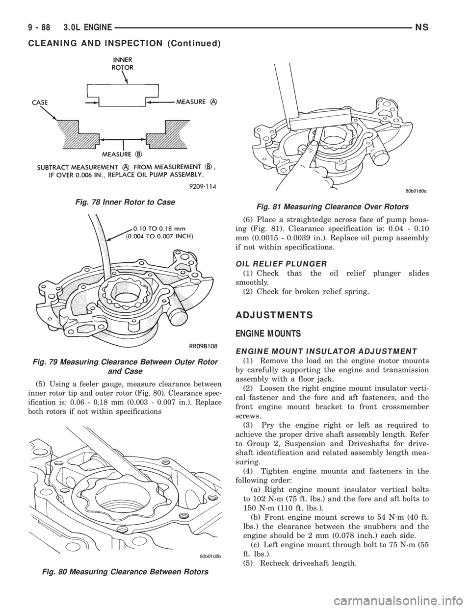
(5)Using a feeler gauge, measure clearance between
inner rotor tip and outer rotor (Fig. 80). Clearance spec-
ification is: 0.06 - 0.18 mm (0.003 - 0.007 in.). Replace
both rotors if not within specifications
(6) Place a straightedge across face of pump hous-
ing (Fig. 81). Clearance specification is: 0.04 - 0.10
mm (0.0015 - 0.0039 in.). Replace oil pump assembly
if not within specifications.
OIL RELIEF PLUNGER
(1) Check that the oil relief plunger slides
smoothly.
(2) Check for broken relief spring.
ADJUSTMENTS
ENGINE MOUNTS
ENGINE MOUNT INSULATOR ADJUSTMENT
(1) Remove the load on the engine motor mounts
by carefully supporting the engine and transmission
assembly with a floor jack.
(2) Loosen the right engine mount insulator verti-
cal fastener and the fore and aft fasteners, and the
front engine mount bracket to front crossmember
screws.
(3) Pry the engine right or left as required to
achieve the proper drive shaft assembly length. Refer
to Group 2, Suspension and Driveshafts for drive-
shaft identification and related assembly length mea-
suring.
(4) Tighten engine mounts and fasteners in the
following order:
(a) Right engine mount insulator vertical bolts
to 102 N´m (75 ft. lbs.) and the fore and aft bolts to
150 N´m (110 ft. lbs.).
(b) Front engine mount screws to 54 N´m (40 ft.
lbs.) the clearance between the snubbers and the
engine should be 2 mm (0.078 inch.) each side.
(c) Left engine mount through bolt to 75 N´m (55
ft. lbs.).
(5) Recheck driveshaft length.
Fig. 78 Inner Rotor to Case
Fig. 79 Measuring Clearance Between Outer Rotor
and Case
Fig. 80 Measuring Clearance Between Rotors
Fig. 81 Measuring Clearance Over Rotors
9 - 88 3.0L ENGINENS
CLEANING AND INSPECTION (Continued)
Page 1152 of 1938
NOTE: Valve seats which are worn or burned can
be reworked, provided that correct angle and seat
width are maintained. Otherwise cylinder head must
be replaced.
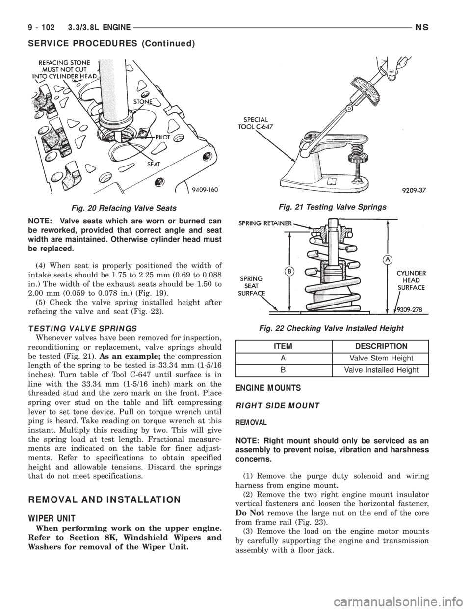
(4) When seat is properly positioned the width of
intake seats should be 1.75 to 2.25 mm (0.69 to 0.088
in.) The width of the exhaust seats should be 1.50 to
2.00 mm (0.059 to 0.078 in.) (Fig. 19).
(5) Check the valve spring installed height after
refacing the valve and seat (Fig. 22).
TESTING VALVE SPRINGS
Whenever valves have been removed for inspection,
reconditioning or replacement, valve springs should
be tested (Fig. 21).As an example;the compression
length of the spring to be tested is 33.34 mm (1-5/16
inches). Turn table of Tool C-647 until surface is in
line with the 33.34 mm (1-5/16 inch) mark on the
threaded stud and the zero mark on the front. Place
spring over stud on the table and lift compressing
lever to set tone device. Pull on torque wrench until
ping is heard. Take reading on torque wrench at this
instant. Multiply this reading by two. This will give
the spring load at test length. Fractional measure-
ments are indicated on the table for finer adjust-
ments. Refer to specifications to obtain specified
height and allowable tensions. Discard the springs
that do not meet specifications.
REMOVAL AND INSTALLATION
WIPER UNIT
When performing work on the upper engine.
Refer to Section 8K, Windshield Wipers and
Washers for removal of the Wiper Unit.
ENGINE MOUNTS
RIGHT SIDE MOUNT
REMOVAL
NOTE: Right mount should only be serviced as an
assembly to prevent noise, vibration and harshness
concerns.
(1) Remove the purge duty solenoid and wiring
harness from engine mount.
(2) Remove the two right engine mount insulator
vertical fasteners and loosen the horizontal fastener,
Do Notremove the large nut on the end of the core
from frame rail (Fig. 23).
(3) Remove the load on the engine motor mounts
by carefully supporting the engine and transmission
assembly with a floor jack.
Fig. 20 Refacing Valve SeatsFig. 21 Testing Valve Springs
Fig. 22 Checking Valve Installed Height
ITEM DESCRIPTION
A Valve Stem Height
B Valve Installed Height
9 - 102 3.3/3.8L ENGINENS
SERVICE PROCEDURES (Continued)
Page 1153 of 1938
(4) Remove the vertical and horizontal fasteners
from the engine side bracket. Remove the engine
mount assembly
INSTALLATION
(1) Reverse removal procedure for installation.
Tighten assembly in the following order:
a. Engine mount to rail fasteners to 68 N´m (50 ft.
lbs.).
b. The vertical engine fastener to 102 N´m (75 ft.
lbs.)
c. The horizontal fastener to 150 N´m (111 ft. lbs.).
(2) Install the purge duty solenoid and wiring har-
ness to the engine mount.
(3) Engine mount adjustment, Refer to Engine
Mount Insulator Adjustment of this section.
FRONT MOUNT
REMOVAL
(1) Support the engine and transmission assembly
with a floor jack so it will not rotate.
(2) Remove the front engine mount through bolt
from the insulator and front crossmember mounting
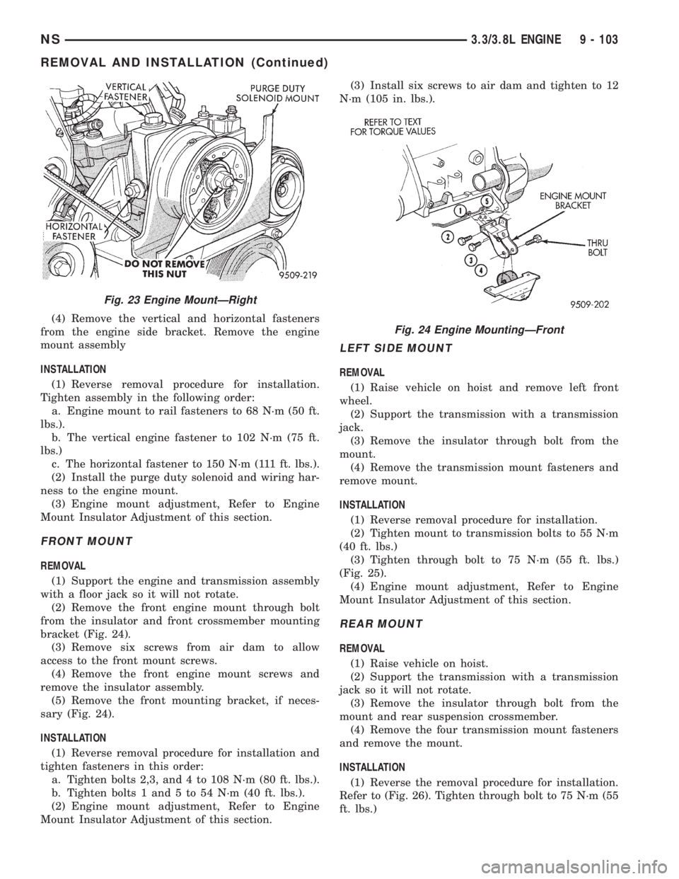
bracket (Fig. 24).
(3) Remove six screws from air dam to allow
access to the front mount screws.
(4) Remove the front engine mount screws and
remove the insulator assembly.
(5) Remove the front mounting bracket, if neces-
sary (Fig. 24).
INSTALLATION
(1) Reverse removal procedure for installation and
tighten fasteners in this order:
a. Tighten bolts 2,3, and 4 to 108 N´m (80 ft. lbs.).
b. Tighten bolts 1 and 5 to 54 N´m (40 ft. lbs.).
(2) Engine mount adjustment, Refer to Engine
Mount Insulator Adjustment of this section.(3) Install six screws to air dam and tighten to 12
N´m (105 in. lbs.).
LEFT SIDE MOUNT
REMOVAL
(1) Raise vehicle on hoist and remove left front
wheel.
(2) Support the transmission with a transmission
jack.
(3) Remove the insulator through bolt from the
mount.
(4) Remove the transmission mount fasteners and
remove mount.
INSTALLATION
(1) Reverse removal procedure for installation.
(2) Tighten mount to transmission bolts to 55 N´m
(40 ft. lbs.)
(3) Tighten through bolt to 75 N´m (55 ft. lbs.)
(Fig. 25).
(4) Engine mount adjustment, Refer to Engine
Mount Insulator Adjustment of this section.
REAR MOUNT
REMOVAL
(1) Raise vehicle on hoist.
(2) Support the transmission with a transmission
jack so it will not rotate.
(3) Remove the insulator through bolt from the
mount and rear suspension crossmember.
(4) Remove the four transmission mount fasteners
and remove the mount.
INSTALLATION
(1) Reverse the removal procedure for installation.
Refer to (Fig. 26). Tighten through bolt to 75 N´m (55
ft. lbs.)
Fig. 23 Engine MountÐRight
Fig. 24 Engine MountingÐFront
NS3.3/3.8L ENGINE 9 - 103
REMOVAL AND INSTALLATION (Continued)