1996 CHRYSLER VOYAGER transmission
[x] Cancel search: transmissionPage 1154 of 1938
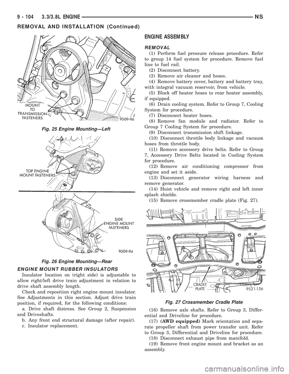
ENGINE MOUNT RUBBER INSULATORS
Insulator location on (right side) is adjustable to
allow right/left drive train adjustment in relation to
drive shaft assembly length.
Check and reposition right engine mount insulator.
See Adjustments in this section. Adjust drive train
position, if required, for the following conditions:
a. Drive shaft distress. See Group 2, Suspension
and Driveshafts.
b. Any front end structural damage (after repair).
c. Insulator replacement.
ENGINE ASSEMBLY
REMOVAL
(1) Perform fuel pressure release procedure. Refer
to group 14 fuel system for procedure. Remove fuel
line to fuel rail.
(2) Disconnect battery.
(3) Remove air cleaner and hoses.
(4) Remove battery cover, battery and battery tray,
with integral vacuum reservoir, from vehicle.
(5) Block off heater hoses to rear heater assembly,
if equipped.
(6) Drain cooling system. Refer to Group 7, Cooling
System for procedure.
(7) Disconnect heater hoses.
(8) Remove fan module and radiator. Refer to
Group 7 Cooling System for procedure.
(9) Disconnect transmission shift linkage.
(10) Disconnect throttle body linkage and vacuum
hoses from throttle body.
(11) Remove accessory drive belts. Refer to Group
7, Accessory Drive Belts located in Cooling System
for procedure.
(12) Remove air conditioning compressor from
engine and set it aside.
(13) Disconnect generator wiring harness and
remove generator.
(14) Hoist vehicle and remove right and left inner
splash shields.
(15) Remove crossmember cradle plate (Fig. 27).
(16) Remove axle shafts. Refer to Group 3, Differ-
ential and Driveline for procedure.
(17)(AWD equipped)Mark orientation and sepa-
rate propeller shaft from power transfer unit. Refer
to Group 3, Differential and Driveline for procedure.
(18) Disconnect exhaust pipe from manifold.
(19) Remove front engine mount and bracket as an
assembly.
Fig. 25 Engine MountingÐLeft
Fig. 26 Engine MountingÐRear
Fig. 27 Crossmember Cradle Plate
9 - 104 3.3/3.8L ENGINENS
REMOVAL AND INSTALLATION (Continued)
Page 1155 of 1938
(20) Remove rear transmission mount and bracket.
(21) Remove power steering pump and bracket
assembly.
(22) Remove wiring harness and connectors from
front of engine.
(23) Remove bending braces and install tool num-
ber 6912 on engine.
(24) Remove transmission inspection cover and
mark flexplate to torque converter.
(25) Remove driveplate to torque converter bolts.
(26) Lower the vehicle.
(27) Remove ground straps to body.
(28) Raise vehicle enough to allow engine dolly
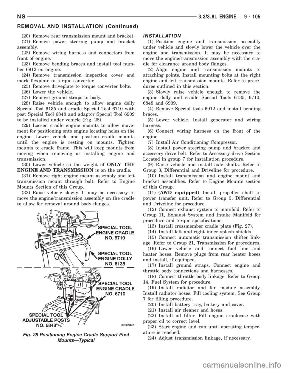
Special Tool 6135 and cradle Special Tool 6710 with
post Special Tool 6848 and adaptor Special Tool 6909
to be installed under vehicle (Fig. 28).
(29) Loosen cradle engine mounts to allow move-
ment for positioning onto engine locating holes on the
engine. Lower vehicle and position cradle mounts
until the engine is resting on mounts. Tighten
mounts to cradle frame. This will keep mounts from
moving when removing or installing engine and
transmission.
(30) Lower vehicle so the weight ofONLY THE
ENGINE AND TRANSMISSIONis on the cradle.
(31) Remove right engine mount assembly and left
transmission mount through bolt. Refer to Engine
Mounts Section of this Group.
(32) Raise vehicle slowly. It may be necessary to
move the engine/transmission assembly on the cradle
to allow for removal around body flanges.INSTALLATION
(1) Position engine and transmission assembly
under vehicle and slowly lower the vehicle over the
engine and transmission. It may be necessary to
move the engine/transmission assembly with the cra-
dle for clearance around body flanges.
(2) Align engine and transmission mounts to
attaching points. Install mounting bolts at the right
engine and left transmission mounts. Refer to proce-
dures outlined in this section.
(3) Slowly raise vehicle enough to remove the
engine dolly and cradle Special Tools 6135, 6710,
6848 and 6909.
(4) Remove Special tools 6912 and install bending
braces.
(5) Lower vehicle. Install generator and wiring
harness.
(6) Connect wiring harness on the front of the
engine.
(7) Install Air Conditioning Compressor.
(8) Install power steering pump and bracket and
accessory drive belt. Refer to Accessory drive Section
Located in group 7 for installation procedure.
(9) Raise vehicle and install axle shafts. Refer to
Group 3, Differential and Driveline for procedure.
(10) Install transmission and engine mount and
bracket assemblies. Refer to Engine Mounts section
of this Group.
(11)(AWD equipped)Install propeller shaft to
power transfer unit. Refer to Group 3, Differential
and Driveline for procedure.
(12) Connect exhaust system to manifold. Refer to
Group 11, Exhaust System and Intake Manifold for
procedure and torque specifications.
(13) Install crossmember cradle plate (Fig. 27).
(14) Install left and right inner splash shields.
(15) Connect automatic transmission shifter link-
age. Refer to Group 21, Transmission for procedures.
(16) Lower vehicle and connect fuel line and
heater hoses. Remove plugs from rear heater hoses
and install, if equipped.
(17) Install ground straps. Connect engine and
throttle body connections and harnesses.
(18) Connect throttle body linkage. Refer to Group
14, Fuel System for procedure.
(19) Install radiator and fan module assembly.
Install radiator hoses. Fill cooling system. See Group
7 for filling procedure.
(20) Install battery tray, battery and cover.
(21) Install air cleaner and hoses.
(22) Install oil filter. Fill engine crankcase with
proper oil to correct level.
(23) Start engine and run until operating temper-
ature is reached.
(24) Adjust transmission linkage, if necessary.
Fig. 28 Positioning Engine Cradle Support Post
MountsÐTypical
NS3.3/3.8L ENGINE 9 - 105
REMOVAL AND INSTALLATION (Continued)
Page 1173 of 1938
ADJUSTMENTS
ENGINE MOUNTS
ENGINE MOUNT INSULATOR ADJUSTMENT
(1) Remove the load on the engine motor mounts
by carefully supporting the engine and transmission
assembly with a floor jack.
(2) Loosen the right engine mount insulator verti-
cal fastener and the fore and aft fasteners, and the
front engine mount bracket to front crossmember
screws.
(3) Pry the engine right or left as required to
achieve the proper drive shaft assembly length. Refer
to Group 2, Suspension and Driveshafts for drive-
shaft identification and related assembly length mea-
suring.
(4) Tighten engine mounts and fasteners in the
following order:
(a) Right engine mount insulator vertical bolts
to 102 N´m (75 ft. lbs.) and the fore and aft bolts to
150 N´m (110 ft. lbs.).
(b) Front engine mount screws to 54 N´m (40 ft.
lbs.) the clearance between the snubbers and the
engine should be 2 mm (0.078 inch.) each side.
(c) Left engine mount through bolt to 75 N´m (55
ft. lbs.).
(5) Recheck driveshaft length.
SPECIFICATIONS
3.3/3.8L ENGINE
Type.........................60É V-6 Engine
Bore±3.3L..................93.0 mm (3.66 in.)
Bore±3.8L.................96.0 mm (3.779 in.)
Stroke±3.3L...............81.0 mm (3.188 in.)
Stroke±3.8L...............87.0 mm (3.425 in.)
Compression Ratio±3.3L.................8.9:1
Compression Ratio±3.8L.................9.6:1
Displacement±3.3L..........3.3L (201 Cubic in.)
Displacement±3.8L..........3.8L (231 Cubic in.)
Brake Horsepower±3.3L........158 @ 4850 RPM
Brake Horsepower±3.8L........180 @ 4400 RPM
Torque±3.3L............203 lb. ft. @ 3600 RPM
Torque±3.8L............240 lb. ft. @ 3600 RPM
Firing Order....................1±2±3±4±5±6
Compression Pressure.Refer to Engine Performance
in Standard Service Procedures.
Cylinder Number (Front to Rear)
Front Bank...........................2,4,6
Rear Bank............................1,3,6
Cylinder Block
Cylinder Bore (Standard)±3.3L.........93.0 mm
(3.66 in.)
Cylinder Bore (Standard)±3.8L.........96.0 mm
(3.779 in.)
Out-of-Round (Max.)........0.076 mm (0.003 in.)
Taper (Max.)..............0.051 mm (0.002 in.)
Cylinder Bore Oversize (Max.).........0.508 mm
(0.020 in.)
Tappet Bore Diameter.....22.9896 - 23.0099 mm
(0.9051 - 0.9059 in.)
Pistons
Type Material.......Aluminum Alloy Tin Coated
Clearance at Size Location......0.025 - 0.057 mm
(0.001 - 0.0022 in.)
Weight (Standard Only)±3.3L......38165 grams
(13.439460.1764 oz.)
Weight (Standard Only)±3.8L......43865 grams
(15.450160.1764 oz.)
Pistons for Service..............Standard Only
Piston Pins
Type .......................Press Fit in Rod
(Serviced as an Assembly)
Diameter.........................22.88 mm
(0.9009 - 0.9007 in.)
Length±3.3L................67.25 - 67.75 mm
(2.648 - 2.667 in.)
Lenth±3.8L.................71.25 - 71.75 mm
(2.805 - 2.824 in.)
Clearance in Piston @ 70É......0.006 - 0.019 mm
(0.0002 - 0.0007 in.)
Clearance in Rod................(Interference)
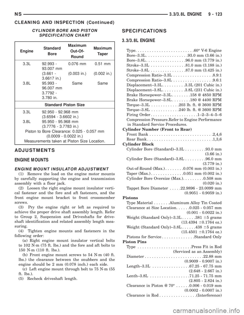
CYLINDER BORE AND PISTON
SPECIFICATION CHART
EngineStandard
BoreMaximum
Out-Of-
RoundMaximum
Taper
3.3L 92.993 -
93.007 mm0.076 mm 0.51 mm
(3.661 -
3.6617 in.)(0.003 in.) (0.002 in.)
3.8L 95.993 -
96.007 mmSame Same
3.7792 -
3.780 in.
Standard Piston Size
3.3L 92.950 - 92.968 mm
(3.6594 - 3.6602 in.)
3.8L 95.950 - 95.968 mm
(3.7776 - 3.7783 in.)
Piston to Bore Clearance: 0.025 - 0.057 mm
(0.0009 - 0.0022 in.)
Measurements taken at Piston Size Location.
NS3.3/3.8L ENGINE 9 - 123
CLEANING AND INSPECTION (Continued)
Page 1195 of 1938
²Turn the ignition switch on and access the ªmis-
cellaneousº screen.
²Select ªre-learn cam/crankº option and follow
directions on DRB screen.
OIL PAN
REMOVAL
(1) Drain engine oil.
(2) Remove transmission inspection cover.
(3) If equipped with air conditioning remove oil fil-
ter and adaptor. Refer to Oil Filter Adapter Removal
and Installation in this section.
(4) Remove oil pan.(5) Clean oil pan and all gasket surfaces.
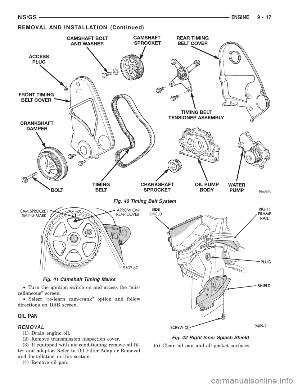
Fig. 40 Timing Belt System
Fig. 41 Camshaft Timing Marks
Fig. 42 Right Inner Splash Shield
NS/GSENGINE 9 - 17
REMOVAL AND INSTALLATION (Continued)
Page 1199 of 1938
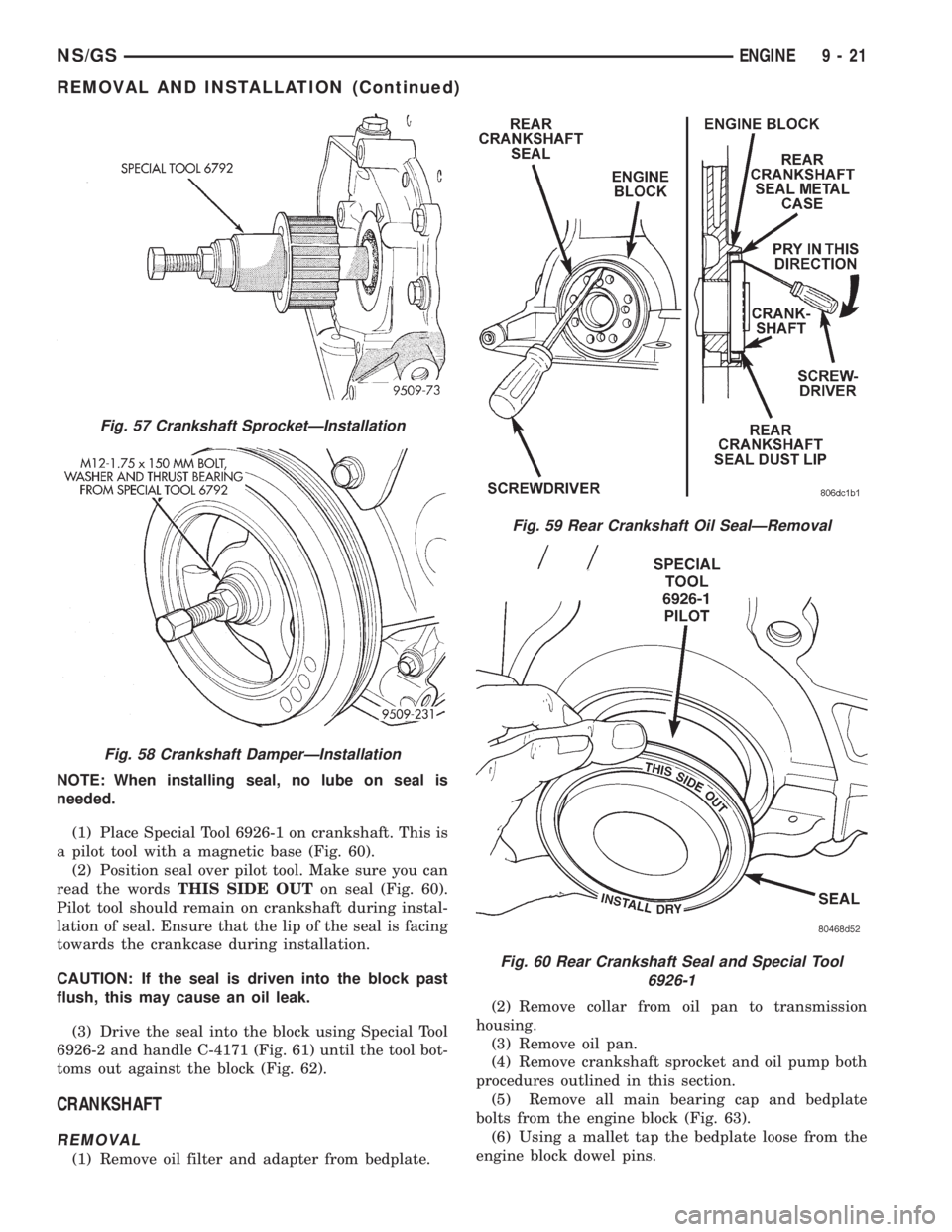
NOTE: When installing seal, no lube on seal is
needed.
(1) Place Special Tool 6926-1 on crankshaft. This is
a pilot tool with a magnetic base (Fig. 60).
(2) Position seal over pilot tool. Make sure you can
read the wordsTHIS SIDE OUTon seal (Fig. 60).
Pilot tool should remain on crankshaft during instal-
lation of seal. Ensure that the lip of the seal is facing
towards the crankcase during installation.
CAUTION: If the seal is driven into the block past
flush, this may cause an oil leak.
(3) Drive the seal into the block using Special Tool
6926-2 and handle C-4171 (Fig. 61) until the tool bot-
toms out against the block (Fig. 62).
CRANKSHAFT
REMOVAL
(1) Remove oil filter and adapter from bedplate.(2) Remove collar from oil pan to transmission
housing.
(3) Remove oil pan.
(4) Remove crankshaft sprocket and oil pump both
procedures outlined in this section.
(5) Remove all main bearing cap and bedplate
bolts from the engine block (Fig. 63).
(6) Using a mallet tap the bedplate loose from the
engine block dowel pins.
Fig. 57 Crankshaft SprocketÐInstallation
Fig. 58 Crankshaft DamperÐInstallation
Fig. 59 Rear Crankshaft Oil SealÐRemoval
Fig. 60 Rear Crankshaft Seal and Special Tool
6926-1
NS/GSENGINE 9 - 21
REMOVAL AND INSTALLATION (Continued)
Page 1229 of 1938
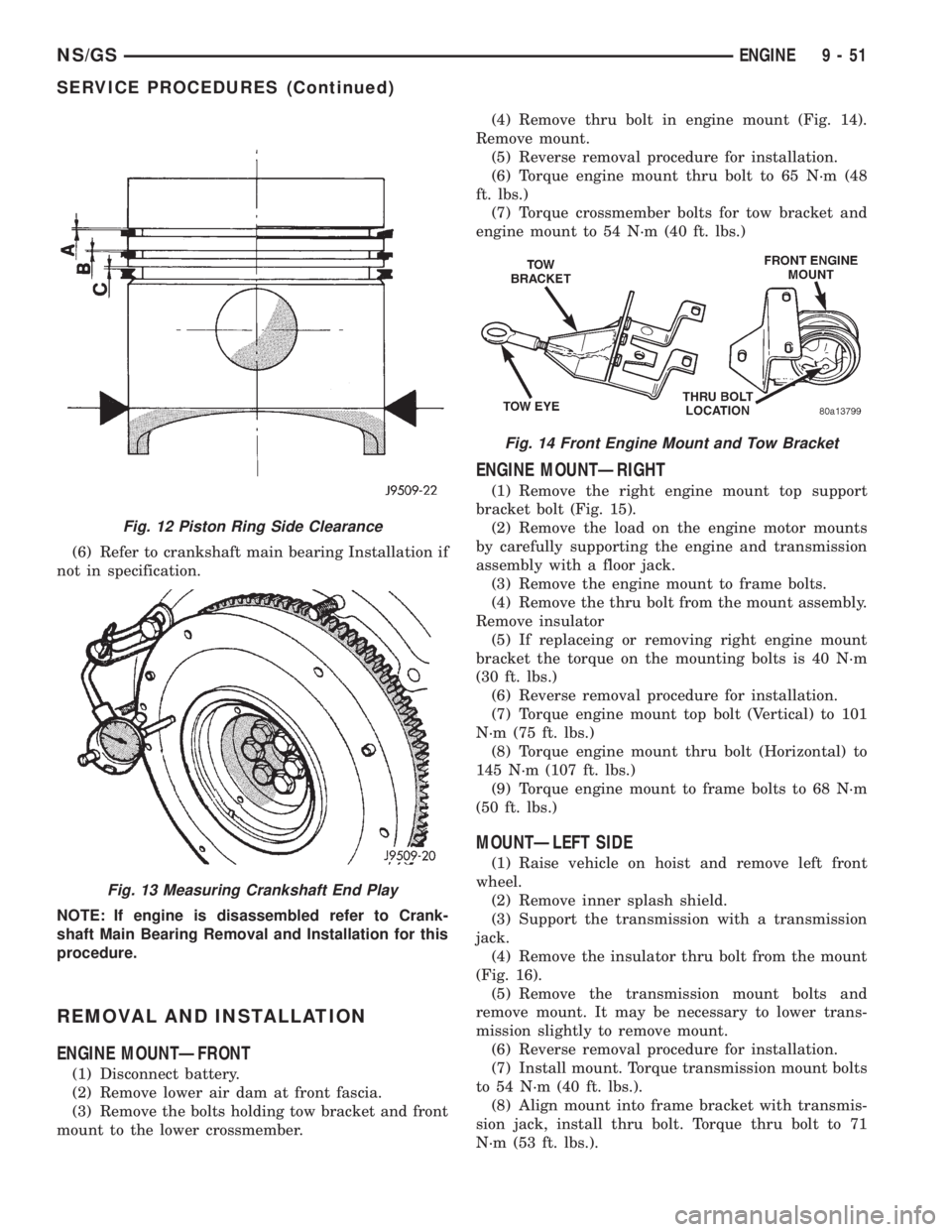
(6) Refer to crankshaft main bearing Installation if
not in specification.
NOTE: If engine is disassembled refer to Crank-
shaft Main Bearing Removal and Installation for this
procedure.
REMOVAL AND INSTALLATION
ENGINE MOUNTÐFRONT
(1) Disconnect battery.
(2) Remove lower air dam at front fascia.
(3) Remove the bolts holding tow bracket and front
mount to the lower crossmember.(4) Remove thru bolt in engine mount (Fig. 14).
Remove mount.
(5) Reverse removal procedure for installation.
(6) Torque engine mount thru bolt to 65 N´m (48
ft. lbs.)
(7) Torque crossmember bolts for tow bracket and
engine mount to 54 N´m (40 ft. lbs.)
ENGINE MOUNTÐRIGHT
(1) Remove the right engine mount top support
bracket bolt (Fig. 15).
(2) Remove the load on the engine motor mounts
by carefully supporting the engine and transmission
assembly with a floor jack.
(3) Remove the engine mount to frame bolts.
(4) Remove the thru bolt from the mount assembly.
Remove insulator
(5) If replaceing or removing right engine mount
bracket the torque on the mounting bolts is 40 N´m
(30 ft. lbs.)
(6) Reverse removal procedure for installation.
(7) Torque engine mount top bolt (Vertical) to 101
N´m (75 ft. lbs.)
(8) Torque engine mount thru bolt (Horizontal) to
145 N´m (107 ft. lbs.)
(9) Torque engine mount to frame bolts to 68 N´m
(50 ft. lbs.)
MOUNTÐLEFT SIDE
(1) Raise vehicle on hoist and remove left front
wheel.
(2) Remove inner splash shield.
(3) Support the transmission with a transmission
jack.
(4) Remove the insulator thru bolt from the mount
(Fig. 16).
(5) Remove the transmission mount bolts and
remove mount. It may be necessary to lower trans-
mission slightly to remove mount.
(6) Reverse removal procedure for installation.
(7) Install mount. Torque transmission mount bolts
to 54 N´m (40 ft. lbs.).
(8) Align mount into frame bracket with transmis-
sion jack, install thru bolt. Torque thru bolt to 71
N´m (53 ft. lbs.).
Fig. 12 Piston Ring Side Clearance
Fig. 13 Measuring Crankshaft End Play
Fig. 14 Front Engine Mount and Tow Bracket
NS/GSENGINE 9 - 51
SERVICE PROCEDURES (Continued)
Page 1230 of 1938
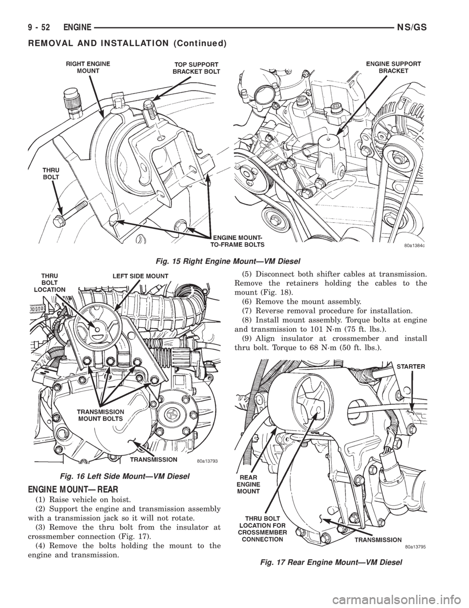
ENGINE MOUNTÐREAR
(1) Raise vehicle on hoist.
(2) Support the engine and transmission assembly
with a transmission jack so it will not rotate.
(3) Remove the thru bolt from the insulator at
crossmember connection (Fig. 17).
(4) Remove the bolts holding the mount to the
engine and transmission.(5) Disconnect both shifter cables at transmission.
Remove the retainers holding the cables to the
mount (Fig. 18).
(6) Remove the mount assembly.
(7) Reverse removal procedure for installation.
(8) Install mount assembly. Torque bolts at engine
and transmission to 101 N´m (75 ft. lbs.).
(9) Align insulator at crossmember and install
thru bolt. Torque to 68 N´m (50 ft. lbs.).
Fig. 15 Right Engine MountÐVM Diesel
Fig. 16 Left Side MountÐVM Diesel
Fig. 17 Rear Engine MountÐVM Diesel
9 - 52 ENGINENS/GS
REMOVAL AND INSTALLATION (Continued)
Page 1231 of 1938
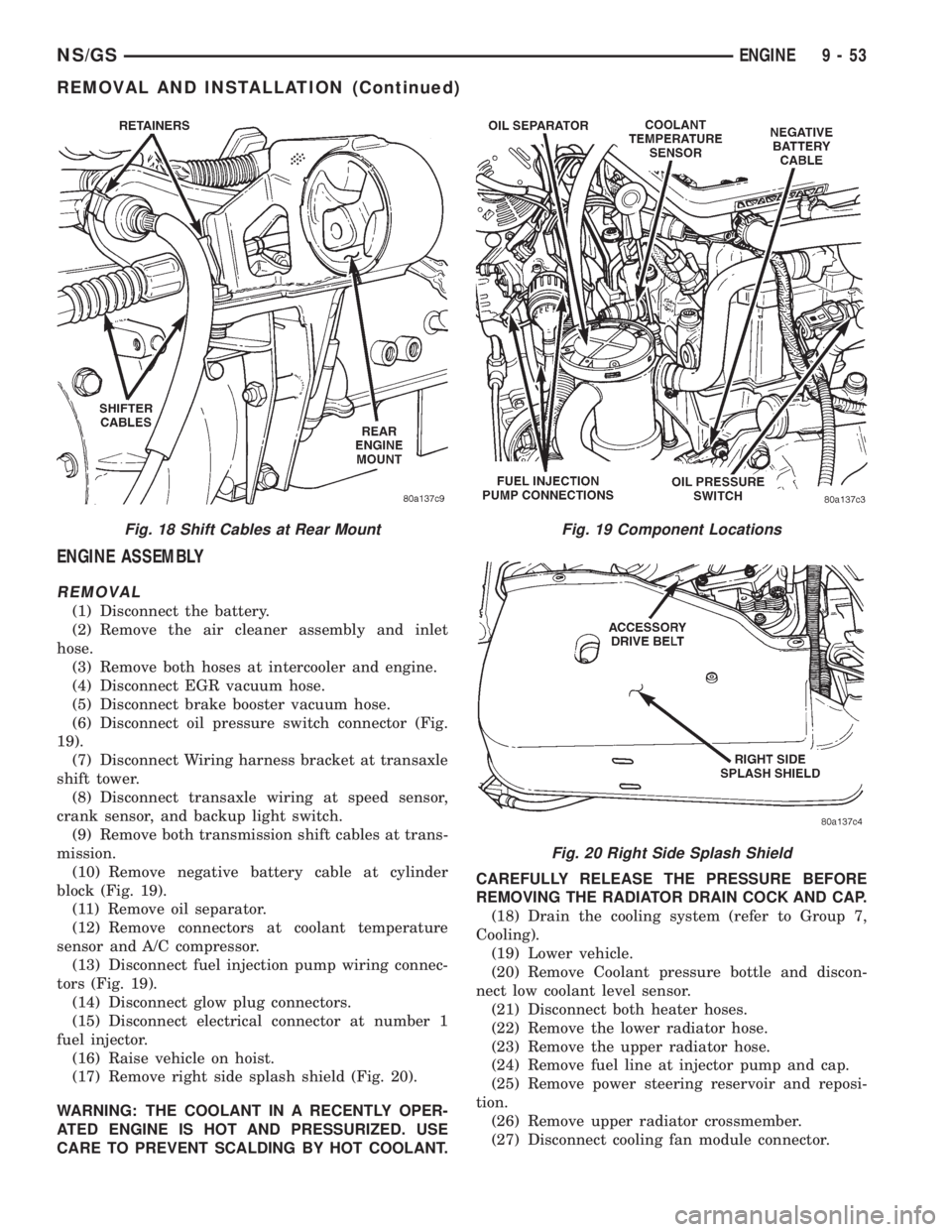
ENGINE ASSEMBLY
REMOVAL
(1) Disconnect the battery.
(2) Remove the air cleaner assembly and inlet
hose.
(3) Remove both hoses at intercooler and engine.
(4) Disconnect EGR vacuum hose.
(5) Disconnect brake booster vacuum hose.
(6) Disconnect oil pressure switch connector (Fig.
19).
(7) Disconnect Wiring harness bracket at transaxle
shift tower.
(8) Disconnect transaxle wiring at speed sensor,
crank sensor, and backup light switch.
(9) Remove both transmission shift cables at trans-
mission.
(10) Remove negative battery cable at cylinder
block (Fig. 19).
(11) Remove oil separator.
(12) Remove connectors at coolant temperature
sensor and A/C compressor.
(13) Disconnect fuel injection pump wiring connec-
tors (Fig. 19).
(14) Disconnect glow plug connectors.
(15) Disconnect electrical connector at number 1
fuel injector.
(16) Raise vehicle on hoist.
(17) Remove right side splash shield (Fig. 20).
WARNING: THE COOLANT IN A RECENTLY OPER-
ATED ENGINE IS HOT AND PRESSURIZED. USE
CARE TO PREVENT SCALDING BY HOT COOLANT.CAREFULLY RELEASE THE PRESSURE BEFORE
REMOVING THE RADIATOR DRAIN COCK AND CAP.
(18) Drain the cooling system (refer to Group 7,
Cooling).
(19) Lower vehicle.
(20) Remove Coolant pressure bottle and discon-
nect low coolant level sensor.
(21) Disconnect both heater hoses.
(22) Remove the lower radiator hose.
(23) Remove the upper radiator hose.
(24) Remove fuel line at injector pump and cap.
(25) Remove power steering reservoir and reposi-
tion.
(26) Remove upper radiator crossmember.
(27) Disconnect cooling fan module connector.
Fig. 18 Shift Cables at Rear MountFig. 19 Component Locations
Fig. 20 Right Side Splash Shield
NS/GSENGINE 9 - 53
REMOVAL AND INSTALLATION (Continued)