1996 CHRYSLER VOYAGER transmission
[x] Cancel search: transmissionPage 1232 of 1938
(28) Remove radiator support bolts.It is neces-
sary to loosen the receiver/dryer to gain access
to the radiator bolts.
(29) Remove radiator and fans as an assembly.
(30) Remove accessory drive belt generator/power
steering. Refer to Group 7, for procedure.
(31) Remove both power steering lines at pump,
and cap both lines.
NOTE: It is not necessary to discharge A/C system
for engine removal.
(32) Remove A/C compressor. Secure compressor
away from engine for clearance during engine
removal.
(33) Remove Generator and adjusting bracket.
NOTE: Do not remove the mounting base from the
generator. It is aligned at the factory and cannot be
realigned in the field.
(34) Hoist vehicle.
(35) Remove exhaust pipe at turbo outlet.
(36) Remove connections at starter.
(37) Remove power steering high pressure line
bracket at rear of oil pan.
(38) Remove both driveshafts from transaxle. Refer
to Group 2, Suspension and Driveshafts.
(39) Disconnect clutch cable at transaxle.
(40) Remove reinforcement plate on lower cross-
member.
(41) Remove front and rear engine mounts. Refer
to procedure outlined in this section.
(42) Drain engine oil and remove oil filter if neces-
sary.
(43) Mount both special tool, engine support brack-
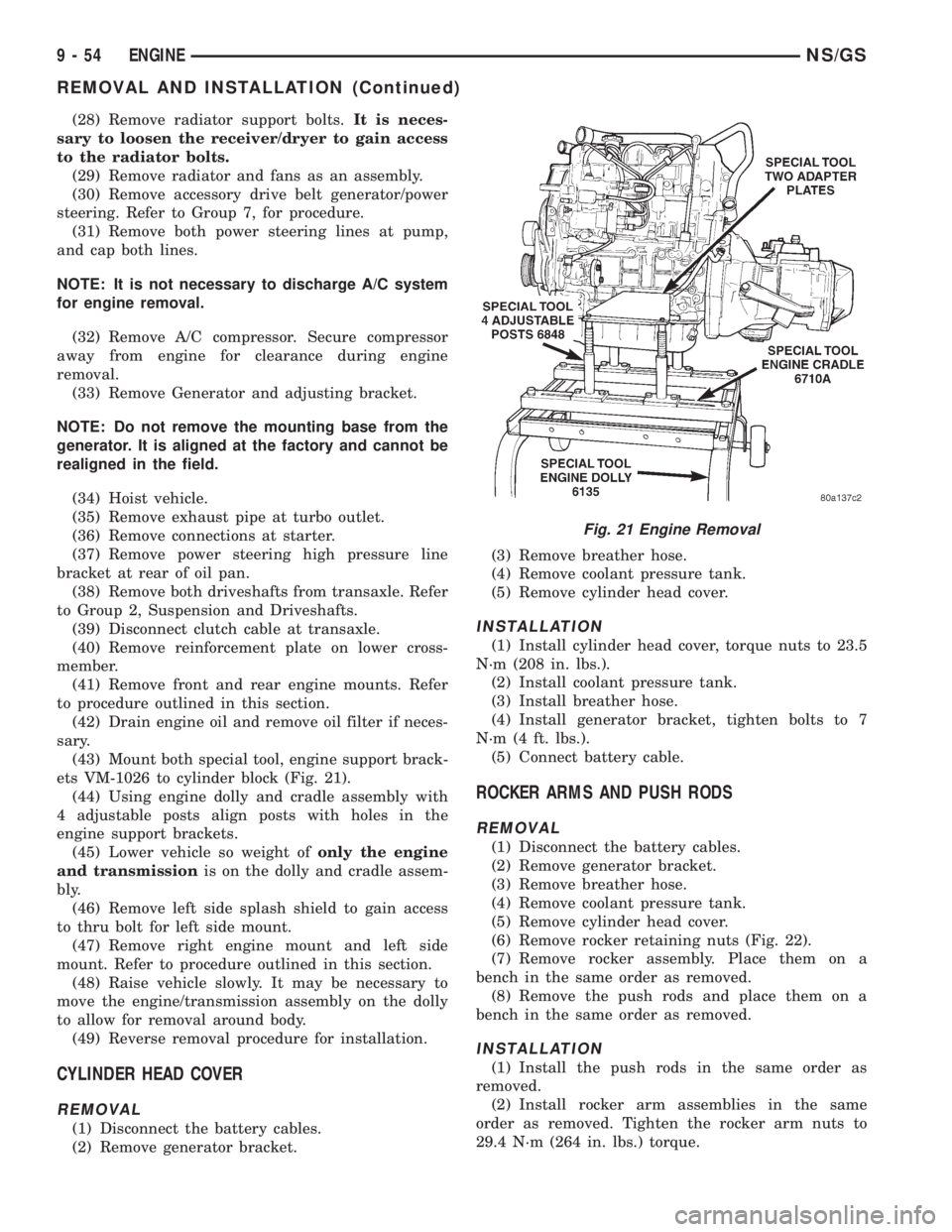
ets VM-1026 to cylinder block (Fig. 21).
(44) Using engine dolly and cradle assembly with
4 adjustable posts align posts with holes in the
engine support brackets.
(45) Lower vehicle so weight ofonly the engine
and transmissionis on the dolly and cradle assem-
bly.
(46) Remove left side splash shield to gain access
to thru bolt for left side mount.
(47) Remove right engine mount and left side
mount. Refer to procedure outlined in this section.
(48) Raise vehicle slowly. It may be necessary to
move the engine/transmission assembly on the dolly
to allow for removal around body.
(49) Reverse removal procedure for installation.
CYLINDER HEAD COVER
REMOVAL
(1) Disconnect the battery cables.
(2) Remove generator bracket.(3) Remove breather hose.
(4) Remove coolant pressure tank.
(5) Remove cylinder head cover.
INSTALLATION
(1) Install cylinder head cover, torque nuts to 23.5
N´m (208 in. lbs.).
(2) Install coolant pressure tank.
(3) Install breather hose.
(4) Install generator bracket, tighten bolts to 7
N´m (4 ft. lbs.).
(5) Connect battery cable.
ROCKER ARMS AND PUSH RODS
REMOVAL
(1) Disconnect the battery cables.
(2) Remove generator bracket.
(3) Remove breather hose.
(4) Remove coolant pressure tank.
(5) Remove cylinder head cover.
(6) Remove rocker retaining nuts (Fig. 22).
(7) Remove rocker assembly. Place them on a
bench in the same order as removed.
(8) Remove the push rods and place them on a
bench in the same order as removed.
INSTALLATION
(1) Install the push rods in the same order as
removed.
(2) Install rocker arm assemblies in the same
order as removed. Tighten the rocker arm nuts to
29.4 N´m (264 in. lbs.) torque.
Fig. 21 Engine Removal
9 - 54 ENGINENS/GS
REMOVAL AND INSTALLATION (Continued)
Page 1243 of 1938
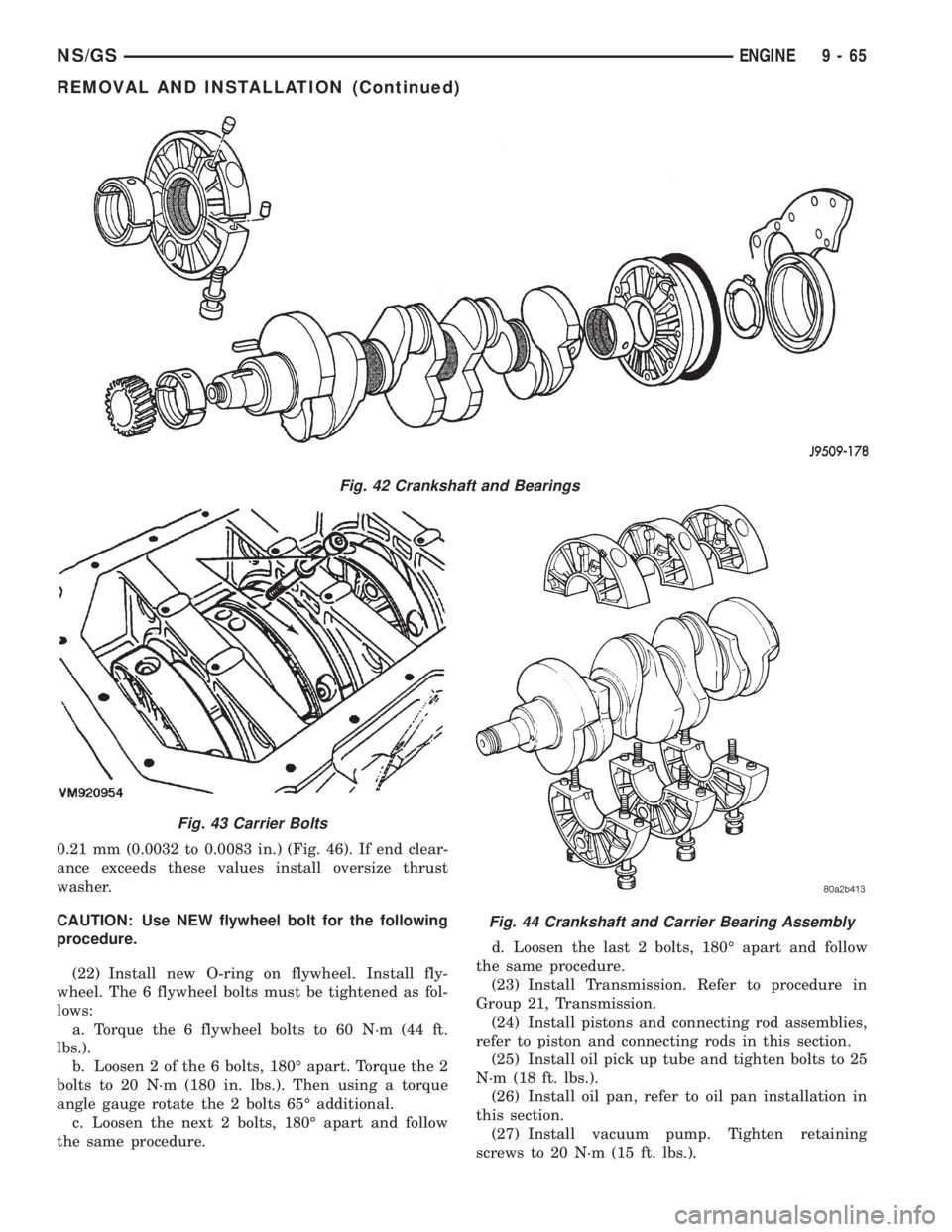
0.21 mm (0.0032 to 0.0083 in.) (Fig. 46). If end clear-
ance exceeds these values install oversize thrust
washer.
CAUTION: Use NEW flywheel bolt for the following
procedure.
(22) Install new O-ring on flywheel. Install fly-
wheel. The 6 flywheel bolts must be tightened as fol-
lows:
a. Torque the 6 flywheel bolts to 60 N´m (44 ft.
lbs.).
b. Loosen 2 of the 6 bolts, 180É apart. Torque the 2
bolts to 20 N´m (180 in. lbs.). Then using a torque
angle gauge rotate the 2 bolts 65É additional.
c. Loosen the next 2 bolts, 180É apart and follow
the same procedure.d. Loosen the last 2 bolts, 180É apart and follow
the same procedure.
(23) Install Transmission. Refer to procedure in
Group 21, Transmission.
(24) Install pistons and connecting rod assemblies,
refer to piston and connecting rods in this section.
(25) Install oil pick up tube and tighten bolts to 25
N´m (18 ft. lbs.).
(26) Install oil pan, refer to oil pan installation in
this section.
(27) Install vacuum pump. Tighten retaining
screws to 20 N´m (15 ft. lbs.).
Fig. 42 Crankshaft and Bearings
Fig. 43 Carrier Bolts
Fig. 44 Crankshaft and Carrier Bearing Assembly
NS/GSENGINE 9 - 65
REMOVAL AND INSTALLATION (Continued)
Page 1250 of 1938
(4) Face chamber recess side of piston towards
camshaft.
(5) Install connecting rod bolt protectors on rod
bolts.
(6) Rotate crankshaft so that the connecting rod
journal is on the center of the cylinder bore. Insert
rod and piston into cylinder bore and guide rod over
the crankshaft journal.
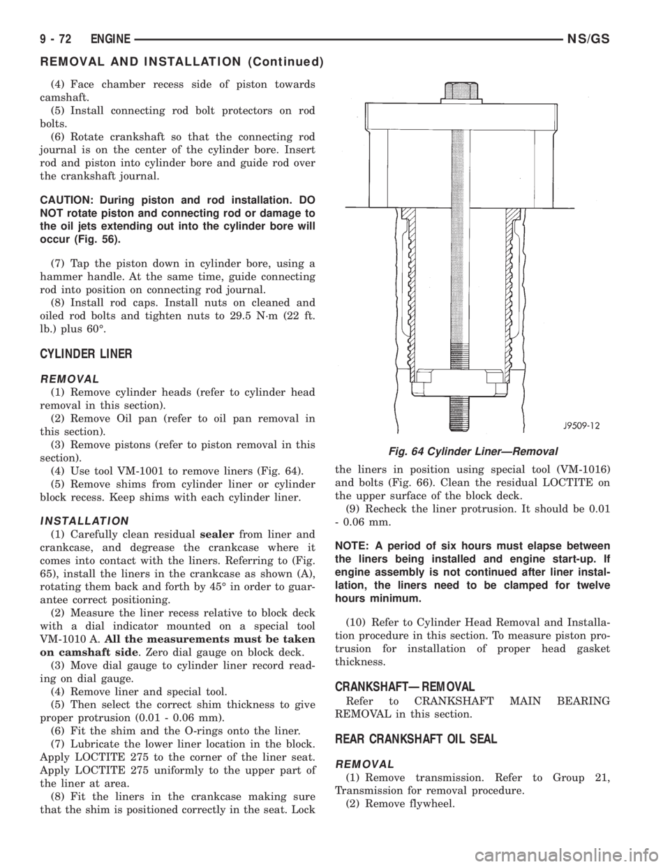
CAUTION: During piston and rod installation. DO
NOT rotate piston and connecting rod or damage to
the oil jets extending out into the cylinder bore will
occur (Fig. 56).
(7) Tap the piston down in cylinder bore, using a
hammer handle. At the same time, guide connecting
rod into position on connecting rod journal.
(8) Install rod caps. Install nuts on cleaned and
oiled rod bolts and tighten nuts to 29.5 N´m (22 ft.
lb.) plus 60É.
CYLINDER LINER
REMOVAL
(1) Remove cylinder heads (refer to cylinder head
removal in this section).
(2) Remove Oil pan (refer to oil pan removal in
this section).
(3) Remove pistons (refer to piston removal in this
section).
(4) Use tool VM-1001 to remove liners (Fig. 64).
(5) Remove shims from cylinder liner or cylinder
block recess. Keep shims with each cylinder liner.
INSTALLATION
(1) Carefully clean residualsealerfrom liner and
crankcase, and degrease the crankcase where it
comes into contact with the liners. Referring to (Fig.
65), install the liners in the crankcase as shown (A),
rotating them back and forth by 45É in order to guar-
antee correct positioning.
(2) Measure the liner recess relative to block deck
with a dial indicator mounted on a special tool
VM-1010 A.All the measurements must be taken
on camshaft side. Zero dial gauge on block deck.
(3) Move dial gauge to cylinder liner record read-
ing on dial gauge.
(4) Remove liner and special tool.
(5) Then select the correct shim thickness to give
proper protrusion (0.01 - 0.06 mm).
(6) Fit the shim and the O-rings onto the liner.
(7) Lubricate the lower liner location in the block.
Apply LOCTITE 275 to the corner of the liner seat.
Apply LOCTITE 275 uniformly to the upper part of
the liner at area.
(8) Fit the liners in the crankcase making sure
that the shim is positioned correctly in the seat. Lockthe liners in position using special tool (VM-1016)
and bolts (Fig. 66). Clean the residual LOCTITE on
the upper surface of the block deck.
(9) Recheck the liner protrusion. It should be 0.01
- 0.06 mm.
NOTE: A period of six hours must elapse between
the liners being installed and engine start-up. If
engine assembly is not continued after liner instal-
lation, the liners need to be clamped for twelve
hours minimum.
(10) Refer to Cylinder Head Removal and Installa-
tion procedure in this section. To measure piston pro-
trusion for installation of proper head gasket
thickness.
CRANKSHAFTÐREMOVAL
Refer to CRANKSHAFT MAIN BEARING
REMOVAL in this section.
REAR CRANKSHAFT OIL SEAL
REMOVAL
(1) Remove transmission. Refer to Group 21,
Transmission for removal procedure.
(2) Remove flywheel.
Fig. 64 Cylinder LinerÐRemoval
9 - 72 ENGINENS/GS
REMOVAL AND INSTALLATION (Continued)
Page 1251 of 1938
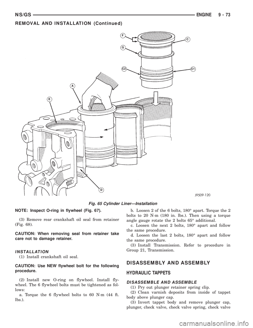
NOTE: Inspect O-ring in flywheel (Fig. 67).
(3) Remove rear crankshaft oil seal from retainer
(Fig. 68).
CAUTION: When removing seal from retainer take
care not to damage retainer.
INSTALLATION
(1) Install crankshaft oil seal.
CAUTION: Use NEW flywheel bolt for the following
procedure.
(2) Install new O-ring on flywheel. Install fly-
wheel. The 6 flywheel bolts must be tightened as fol-
lows:
a. Torque the 6 flywheel bolts to 60 N´m (44 ft.
lbs.).b. Loosen 2 of the 6 bolts, 180É apart. Torque the 2
bolts to 20 N´m (180 in. lbs.). Then using a torque
angle gauge rotate the 2 bolts 65É additional.
c. Loosen the next 2 bolts, 180É apart and follow
the same procedure.
d. Loosen the last 2 bolts, 180É apart and follow
the same procedure.
(3) Install Transmission. Refer to procedure in
Group 21, Transmission.
DISASSEMBLY AND ASSEMBLY
HYDRAULIC TAPPETS
DISASSEMBLE AND ASSEMBLE
(1) Pry out plunger retainer spring clip.
(2) Clean varnish deposits from inside of tappet
body above plunger cap.
(3) Invert tappet body and remove plunger cap,
plunger, check valve, check valve spring, check valve
Fig. 65 Cylinder LinerÐInstallation
NS/GSENGINE 9 - 73
REMOVAL AND INSTALLATION (Continued)
Page 1258 of 1938
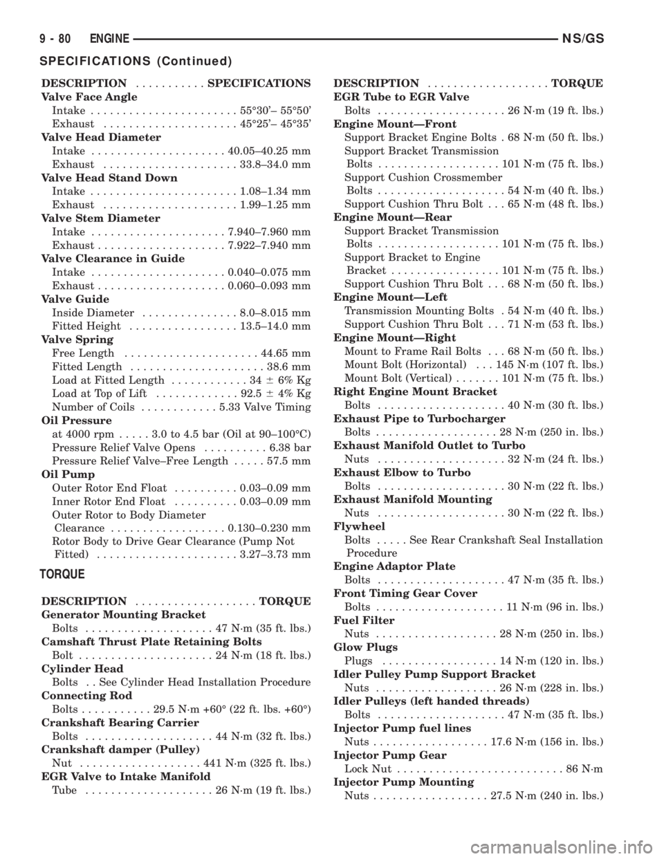
DESCRIPTION...........SPECIFICATIONS
Valve Face Angle
Intake.......................55É30'± 55É50'
Exhaust.....................45É25'± 45É35'
Valve Head Diameter
Intake.....................40.05±40.25 mm
Exhaust.....................33.8±34.0 mm
Valve Head Stand Down
Intake.......................1.08±1.34 mm
Exhaust.....................1.99±1.25 mm
Valve Stem Diameter
Intake.....................7.940±7.960 mm
Exhaust....................7.922±7.940 mm
Valve Clearance in Guide
Intake.....................0.040±0.075 mm
Exhaust....................0.060±0.093 mm
Valve Guide
Inside Diameter...............8.0±8.015 mm
Fitted Height.................13.5±14.0 mm
Valve Spring
Free Length.....................44.65 mm
Fitted Length.....................38.6 mm
Load at Fitted Length............3466% Kg
Load at Top of Lift.............92.564% Kg
Number of Coils............5.33 Valve Timing
Oil Pressure
at 4000 rpm.....3.0to4.5bar(Oil at 90±100ÉC)
Pressure Relief Valve Opens..........6.38 bar
Pressure Relief Valve±Free Length.....57.5 mm
Oil Pump
Outer Rotor End Float..........0.03±0.09 mm
Inner Rotor End Float..........0.03±0.09 mm
Outer Rotor to Body Diameter
Clearance..................0.130±0.230 mm
Rotor Body to Drive Gear Clearance (Pump Not
Fitted)......................3.27±3.73 mm
TORQUE
DESCRIPTION...................TORQUE
Generator Mounting Bracket
Bolts....................47N´m(35ft.lbs.)
Camshaft Thrust Plate Retaining Bolts
Bolt.....................24N´m(18ft.lbs.)
Cylinder Head
Bolts . . See Cylinder Head Installation Procedure
Connecting Rod
Bolts...........29.5 N´m +60É (22 ft. lbs. +60É)
Crankshaft Bearing Carrier
Bolts....................44N´m(32ft.lbs.)
Crankshaft damper (Pulley)
Nut ...................441N´m(325 ft. lbs.)
EGR Valve to Intake Manifold
Tube ....................26N´m(19ft.lbs.)DESCRIPTION...................TORQUE
EGR Tube to EGR Valve
Bolts....................26N´m(19ft.lbs.)
Engine MountÐFront
Support Bracket Engine Bolts . 68 N´m (50 ft. lbs.)
Support Bracket Transmission
Bolts...................101N´m(75ft.lbs.)
Support Cushion Crossmember
Bolts....................54N´m(40ft.lbs.)
Support Cushion Thru Bolt . . . 65 N´m (48 ft. lbs.)
Engine MountÐRear
Support Bracket Transmission
Bolts...................101N´m(75ft.lbs.)
Support Bracket to Engine
Bracket.................101N´m(75ft.lbs.)
Support Cushion Thru Bolt . . . 68 N´m (50 ft. lbs.)
Engine MountÐLeft
Transmission Mounting Bolts . 54 N´m (40 ft. lbs.)
Support Cushion Thru Bolt . . . 71 N´m (53 ft. lbs.)
Engine MountÐRight
Mount to Frame Rail Bolts . . . 68 N´m (50 ft. lbs.)
Mount Bolt (Horizontal) . . . 145 N´m (107 ft. lbs.)
Mount Bolt (Vertical).......101N´m(75ft.lbs.)
Right Engine Mount Bracket
Bolts....................40N´m(30ft.lbs.)
Exhaust Pipe to Turbocharger
Bolts...................28N´m(250 in. lbs.)
Exhaust Manifold Outlet to Turbo
Nuts....................32N´m(24ft.lbs.)
Exhaust Elbow to Turbo
Bolts....................30N´m(22ft.lbs.)
Exhaust Manifold Mounting
Nuts....................30N´m(22ft.lbs.)
Flywheel
Bolts.....SeeRear Crankshaft Seal Installation
Procedure
Engine Adaptor Plate
Bolts....................47N´m(35ft.lbs.)
Front Timing Gear Cover
Bolts....................11N´m(96in.lbs.)
Fuel Filter
Nuts...................28N´m(250 in. lbs.)
Glow Plugs
Plugs..................14N´m(120 in. lbs.)
Idler Pulley Pump Support Bracket
Nuts...................26N´m(228 in. lbs.)
Idler Pulleys (left handed threads)
Bolts....................47N´m(35ft.lbs.)
Injector Pump fuel lines
Nuts..................17.6 N´m (156 in. lbs.)
Injector Pump Gear
Lock Nut..........................86N´m
Injector Pump Mounting
Nuts..................27.5 N´m (240 in. lbs.)
9 - 80 ENGINENS/GS
SPECIFICATIONS (Continued)
Page 1303 of 1938
FUEL LEVEL SENSOR
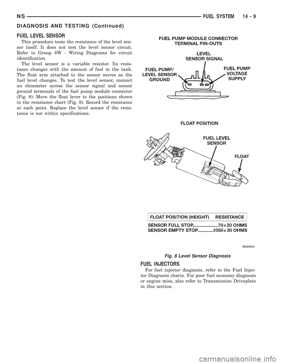
This procedure tests the resistance of the level sen-
sor itself. It does not test the level sensor circuit.
Refer to Group 8W - Wiring Diagrams for circuit
identification.
The level sensor is a variable resistor. Its resis-
tance changes with the amount of fuel in the tank.
The float arm attached to the sensor moves as the
fuel level changes. To test the level sensor, connect
an ohmmeter across the sensor signal and sensor
ground terminals of the fuel pump module connector
(Fig. 8). Move the float lever to the positions shown
in the resistance chart (Fig. 8). Record the resistance
at each point. Replace the level sensor if the resis-
tance is not within specifications.
FUEL INJECTORS
For fuel injector diagnosis, refer to the Fuel Injec-
tor Diagnosis charts. For poor fuel economy diagnosis
or engine miss, also refer to Transmission Driveplate
in this section.
Fig. 8 Level Sensor Diagnosis
NSFUEL SYSTEM 14 - 9
DIAGNOSIS AND TESTING (Continued)
Page 1307 of 1938
WARNING: RELEASE FUEL SYSTEM PRESSURE
BEFORE DISCONNECTING QUICK-CONNECT FIT-
TINGS AT FUEL FILTER. REFER TO THE FUEL
PRESSURE RELEASE PROCEDURE.
REMOVAL
(1) Perform fuel system pressure release.
(2) Disconnect quick-connect fittings from fuel
pump module and chassis fuel supply tube. Refer to
Quick-Connect Fittings in this section.
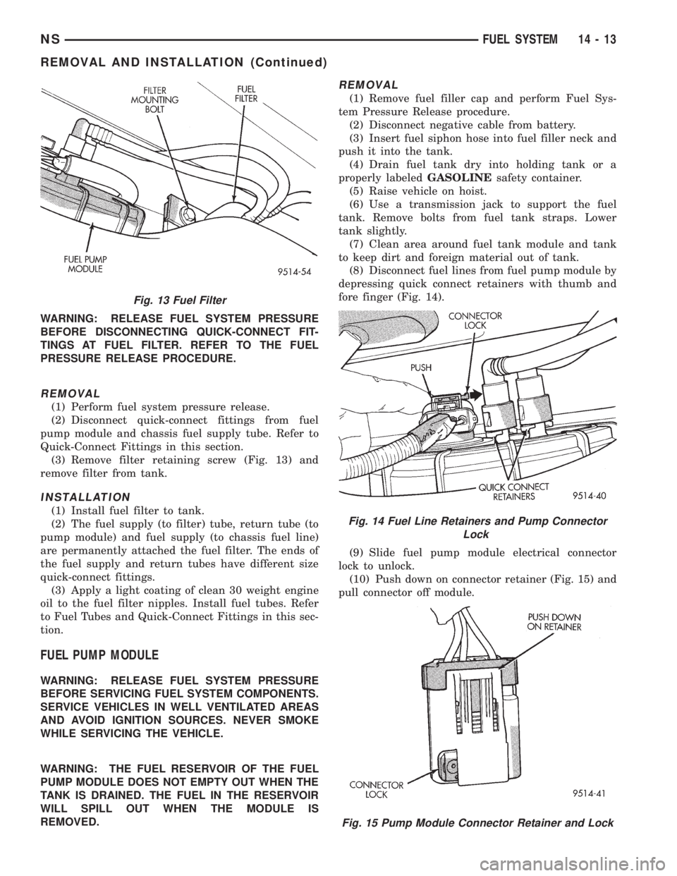
(3) Remove filter retaining screw (Fig. 13) and
remove filter from tank.
INSTALLATION
(1) Install fuel filter to tank.
(2) The fuel supply (to filter) tube, return tube (to
pump module) and fuel supply (to chassis fuel line)
are permanently attached the fuel filter. The ends of
the fuel supply and return tubes have different size
quick-connect fittings.
(3) Apply a light coating of clean 30 weight engine
oil to the fuel filter nipples. Install fuel tubes. Refer
to Fuel Tubes and Quick-Connect Fittings in this sec-
tion.
FUEL PUMP MODULE
WARNING: RELEASE FUEL SYSTEM PRESSURE
BEFORE SERVICING FUEL SYSTEM COMPONENTS.
SERVICE VEHICLES IN WELL VENTILATED AREAS
AND AVOID IGNITION SOURCES. NEVER SMOKE
WHILE SERVICING THE VEHICLE.
WARNING: THE FUEL RESERVOIR OF THE FUEL
PUMP MODULE DOES NOT EMPTY OUT WHEN THE
TANK IS DRAINED. THE FUEL IN THE RESERVOIR
WILL SPILL OUT WHEN THE MODULE IS
REMOVED.
REMOVAL
(1) Remove fuel filler cap and perform Fuel Sys-
tem Pressure Release procedure.
(2) Disconnect negative cable from battery.
(3) Insert fuel siphon hose into fuel filler neck and
push it into the tank.
(4) Drain fuel tank dry into holding tank or a
properly labeledGASOLINEsafety container.
(5) Raise vehicle on hoist.
(6) Use a transmission jack to support the fuel
tank. Remove bolts from fuel tank straps. Lower
tank slightly.
(7) Clean area around fuel tank module and tank
to keep dirt and foreign material out of tank.
(8) Disconnect fuel lines from fuel pump module by
depressing quick connect retainers with thumb and
fore finger (Fig. 14).
(9) Slide fuel pump module electrical connector
lock to unlock.
(10) Push down on connector retainer (Fig. 15) and
pull connector off module.
Fig. 13 Fuel Filter
Fig. 14 Fuel Line Retainers and Pump Connector
Lock
Fig. 15 Pump Module Connector Retainer and Lock
NSFUEL SYSTEM 14 - 13
REMOVAL AND INSTALLATION (Continued)
Page 1311 of 1938
(7) Install fuel pump module. Refer to Fuel Pump
Module in this section.
FUEL TANK
WARNING: RELEASE FUEL SYSTEM PRESSURE
BEFORE SERVICING FUEL SYSTEM COMPONENTS.
SERVICE VEHICLES IN WELL VENTILATED AREAS
AND AVOID IGNITION SOURCES. NEVER SMOKE
WHILE SERVICING THE VEHICLE.
REMOVAL
(1) Disconnect negative cable from battery.
(2) Remove fuel filler cap and perform Fuel Sys-
tem Pressure Release procedure.
(3) Insert fuel siphon hose into fuel filler neck and
push it into the tank.
(4) Drain fuel tank dry into holding tank or a
properly labeledGASOLINEsafety container.
(5) Raise vehicle on hoist.
(6) Disconnect both the fuel fill and fuel vent rub-
ber hoses at the fuel tank.(7) Disconnect fuel supply lines from the steel sup-
ply line.
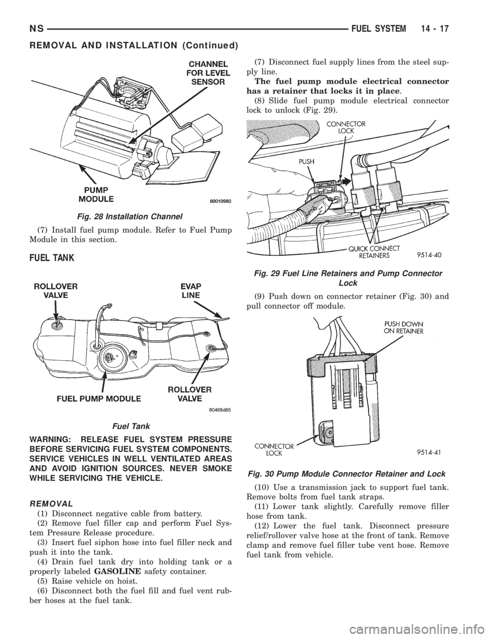
The fuel pump module electrical connector
has a retainer that locks it in place.
(8) Slide fuel pump module electrical connector
lock to unlock (Fig. 29).
(9) Push down on connector retainer (Fig. 30) and
pull connector off module.
(10) Use a transmission jack to support fuel tank.
Remove bolts from fuel tank straps.
(11) Lower tank slightly. Carefully remove filler
hose from tank.
(12) Lower the fuel tank. Disconnect pressure
relief/rollover valve hose at the front of tank. Remove
clamp and remove fuel filler tube vent hose. Remove
fuel tank from vehicle.
Fig. 28 Installation Channel
Fuel Tank
Fig. 29 Fuel Line Retainers and Pump Connector
Lock
Fig. 30 Pump Module Connector Retainer and Lock
NSFUEL SYSTEM 14 - 17
REMOVAL AND INSTALLATION (Continued)