1996 CHRYSLER VOYAGER fuel consumption
[x] Cancel search: fuel consumptionPage 1297 of 1938

CRUISING RANGE
Because E-85 fuel contains less energy per gallon
than gasoline, you will experience an increase in fuel
consumption. You can expect your MPG and your
driving range to decrease by about 30% compared to
gasoline operation.
REPLACEMENT PARTS
Many components in your Flexible Fuel Vehicle
(FFV) are designed to be compatible with ethanol.Always be sure that your vehicle is serviced with cor-
rect ethanol compatible parts.
CAUTION: Replacing fuel system components with
non-ethanol compatible components can damage
your vehicle and may void the warranty.
NSFUEL SYSTEM 14 - 3
GENERAL INFORMATION (Continued)
Page 1381 of 1938

A defective fuel injection pump, defective fuel tim-
ing solenoid or misadjusted mechanical pump timing
can cause starting problems or prevent the engine
from revving up. It can also cause:
²Engine surge at idle
²Rough idle (warm engine)
²Low power
²Excessive fuel consumption
²Poor performance
²Low power
²Black smoke from the exhaust
²Blue or white fog like exhaust
²Incorrect idle or maximum speed
The electronically controlled fuel pump has no
mechanical governor like older mechanically con-
trolled fuel pumps. Do not remove the top cover of
the fuel pump, or the screws fastening the wiring
pigtail to the side of the pump.The warranty of
the injection pump and the engine may be void
if those seals have been removed or tampered
with.
FUEL SUPPLY RESTRICTIONS
LOW±PRESSURE LINES
Restricted or Plugged supply lines or fuel filter can
cause a timing fault that will cause the PCM to oper-
ate the engine in a ªLimp Homeº mode. See the
introduction of the Fuel Injection System in this
group for more information on the Limp Home mode.
Fuel supply line restrictions can cause starting prob-
lems and prevent the engine from revving up. The
starting problems include; low power and blue or
white fog like exhaust. Test all fuel supply lines for
restrictions or blockage. Flush or replace as neces-
sary. Bleed the fuel system of air once a fuel supply
line has been replaced. Refer to the Air Bleed Proce-
dure section of this group for procedures.
HIGH±PRESSURE LINES
Restricted (kinked or bent) high±pressure lines can
cause starting problems, poor engine performance
and black smoke from exhaust.
Examine all high±pressure lines for any damage.
Each radius on each high±pressure line must be
smooth and free of any bends or kinks.
Replace damaged, restricted or leaking high±pres-
sure fuel lines with the correct replacement line.
CAUTION: The high±pressure fuel lines must be
clamped securely in place in the holders. The lines
cannot contact each other or other components. Do
not attempt to weld high±pressure fuel lines or to
repair lines that are damaged. Only use the recom-
mended lines when replacement of high±pressure
fuel line is necessary.
FUEL SHUTDOWN SOLENOID TEST
Since diesel fuel injection does not use spark plugs
to start combustion, the only way to stop the engine
is to cut off the fuel supply. This is done with the
Fuel Shutdown Solenoid. If the engine cranks, but
refuses to start, it may be caused by a defective fuel
shutdown solenoid.
The fuel shutdown solenoid is not controlled
or operated by the PCM.Voltage to operate the
solenoid is supplied from the ignition (key) switch.
NOTE: Although the fuel shutdown solenoid is not
operated by the PCM, if the Fuel Shutdown Solenoid
has been disconnected, and the key turned on, the
PCM will sense that the solenoid is not in the circuit,
and will switch to a ªLimp Homeº mode. After recon-
necting the solenoid, the PCM will have to be reset
by clearing the codes with the DRBIII scan tool, or
disconnecting the vehicle's battery for several min-
utes. The DRBIII scan tool is the preferred method
for resetting the PCM. Refer to the 1998 GS 2.5L Die-
sel Powertrain Diagnostic Manual for procedure.
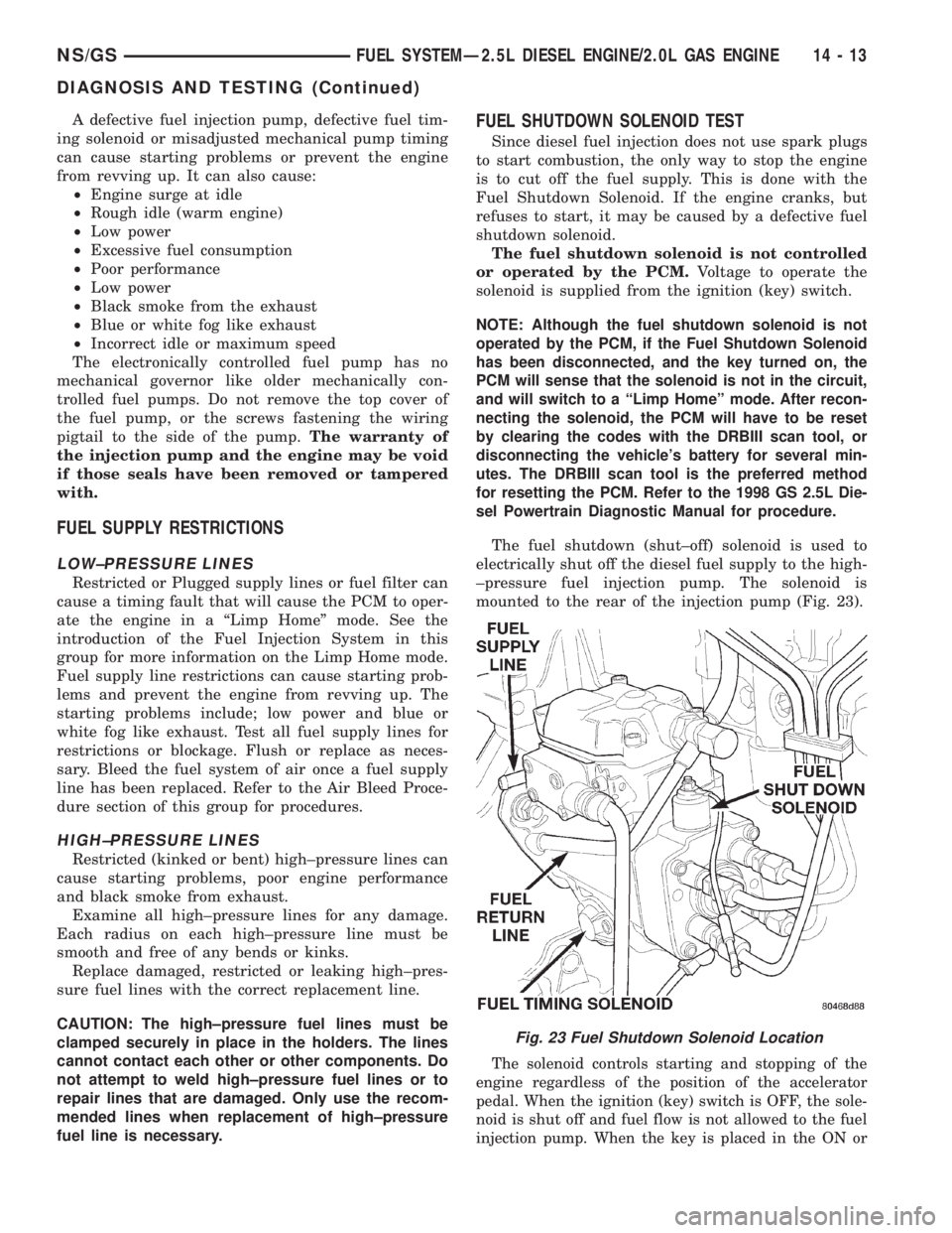
The fuel shutdown (shut±off) solenoid is used to
electrically shut off the diesel fuel supply to the high-
±pressure fuel injection pump. The solenoid is
mounted to the rear of the injection pump (Fig. 23).
The solenoid controls starting and stopping of the
engine regardless of the position of the accelerator
pedal. When the ignition (key) switch is OFF, the sole-
noid is shut off and fuel flow is not allowed to the fuel
injection pump. When the key is placed in the ON or
Fig. 23 Fuel Shutdown Solenoid Location
NS/GSFUEL SYSTEMÐ2.5L DIESEL ENGINE/2.0L GAS ENGINE 14 - 13
DIAGNOSIS AND TESTING (Continued)
Page 1915 of 1938

components now have input (rationality) and output
(functionality) checks. Previously, a component like
the Throttle Position sensor (TPS) was checked by
the PCM for an open or shorted circuit. If one of
these conditions occurred, a DTC was set. Now there
is a check to ensure that the component is working.
This is done by watching for a TPS indication of a
greater or lesser throttle opening than MAP and
engine rpm indicate. In the case of the TPS, if engine
vacuum is high and engine rpm is 1600 or greater
and the TPS indicates a large throttle opening, a
DTC will be set. The same applies to low vacuum
and 1600 rpm.
Any component that has an associated limp in will
set a fault after 1 trip with the malfunction present.
Refer to the Diagnostic Trouble Codes Description
Charts in this section and the appropriate Power-
train Diagnostic Procedure Manual for diagnostic
procedures.
NON-MONITORED CIRCUITS
The PCM does not monitor all circuits, systems
and conditions that could have malfunctions causing
driveability problems. However, problems with these
systems may cause the PCM to store diagnostic trou-
ble codes for other systems or components. For exam-
ple, a fuel pressure problem will not register a fault
directly, but could cause a rich/lean condition or mis-
fire. This could cause the PCM to store an oxygen
sensor or misfire diagnostic trouble code.
The major non-monitored circuits are listed below
along with examples of failures modes that do not
directly cause the PCM to set a DTC, but for a sys-
tem that is monitored.
FUEL PRESSURE
The fuel pressure regulator controls fuel system
pressure. The PCM cannot detect a clogged fuel
pump inlet filter, clogged in-line fuel filter, or a
pinched fuel supply or return line. However, these
could result in a rich or lean condition causing the
PCM to store an oxygen sensor or fuel system diag-
nostic trouble code.
SECONDARY IGNITION CIRCUIT
The PCM cannot detect an inoperative ignition coil,
fouled or worn spark plugs, ignition cross firing, or
open spark plug cables.
CYLINDER COMPRESSION
The PCM cannot detect uneven, low, or high engine
cylinder compression.
EXHAUST SYSTEM
The PCM cannot detect a plugged, restricted or
leaking exhaust system. It may set a EGR or Fuel
system fault or O2S.
FUEL INJECTOR MECHANICAL
MALFUNCTIONS
The PCM cannot determine if a fuel injector is
clogged, the needle is sticking or if the wrong injector
is installed. However, these could result in a rich or
lean condition causing the PCM to store a diagnostic
trouble code for either misfire, an oxygen sensor, or
the fuel system.
EXCESSIVE OIL CONSUMPTION
Although the PCM monitors engine exhaust oxygen
content when the system is in closed loop, it cannot
determine excessive oil consumption.
THROTTLE BODY AIR FLOW
The PCM cannot detect a clogged or restricted air
cleaner inlet or filter element.
VACUUM ASSIST
The PCM cannot detect leaks or restrictions in the
vacuum circuits of vacuum assisted engine control
system devices. However, these could cause the PCM
to store a MAP sensor diagnostic trouble code and
cause a high idle condition.
PCM SYSTEM GROUND
The PCM cannot determine a poor system ground.
However, one or more diagnostic trouble codes may
be generated as a result of this condition. The mod-
ule should be mounted to the body at all times, also
during diagnostic.
PCM CONNECTOR ENGAGEMENT
The PCM may not be able to determine spread or
damaged connector pins. However, it might store
diagnostic trouble codes as a result of spread connec-
tor pins.
HIGH AND LOW LIMITS
The PCM compares input signal voltages from each
input device with established high and low limits for
the device. If the input voltage is not within limits
and other criteria are met, the PCM stores a diagnos-
tic trouble code in memory. Other diagnostic trouble
code criteria might include engine RPM limits or
input voltages from other sensors or switches that
must be present before verifying a diagnostic trouble
code condition.
NSEMISSION CONTROL SYSTEMS 25 - 11
DESCRIPTION AND OPERATION (Continued)