1996 CHRYSLER VOYAGER adding oil
[x] Cancel search: adding oilPage 215 of 1938

COOLING SYSTEM
CONTENTS
page page
GENERAL INFORMATION
ACCESSORY DRIVE BELTS................ 1
AUTOMATIC TRANSMISSION OIL COOLERÐ
2.4L................................. 3
COOLANT RECOVERY SYSTEM (CRS)....... 3
COOLANT.............................. 3
COOLING SYSTEM....................... 2
ENGINE BLOCK HEATER.................. 5
ENGINE THERMOSTAT.................... 3
RADIATOR PRESSURE CAP................ 4
RADIATOR............................. 3
WATER PUMPS......................... 3
DESCRIPTION AND OPERATION
COOLANT PERFORMANCE................. 6
RADIATOR HOSES AND CLAMPS........... 6
WATER PIPESÐ3.0L ENGINE.............. 6
WATER PUMPÐ3.3/3.8L ENGINES.......... 7
WATER PUMPÐ2.4L ENGINE.............. 6
WATER PUMPÐ3.0L ENGINE.............. 6
DIAGNOSIS AND TESTING
ACCESSORY DRIVE BELT.................. 7
COOLING SYSTEM DIAGNOSIS............. 8
DEAERATION.......................... 16
ELECTRIC FAN MOTOR TEST.............. 14
LOW COOLANT LEVEL AERATION.......... 15
PRESSURE TESTING RADIATOR CAP....... 15
RADIATOR CAP TO FILLER NECK SEAL
PRESSURE RELIEF CHECK.............. 15
RADIATOR COOLANT FLOW TEST.......... 14
RADIATOR FAN CONTROL................ 14
TEMPERATURE GAUGE INDICATION........ 16
TESTING COOLING SYSTEM FOR LEAKS.... 14
SERVICE PROCEDURES
COOLANT LEVEL CHECKÐROUTINE........ 16
COOLANT LEVEL SERVICE................ 16COOLANTÐADDING ADDITIONAL.......... 16
COOLING SYSTEMÐDRAINING............ 16
COOLING SYSTEMÐREFILLING........... 16
REMOVAL AND INSTALLATION
ACCESSORY DRIVE BELTSÐ2.4L.......... 23
ACCESSORY DRIVE BELTSÐ3.0L.......... 24
ACCESSORY DRIVE BELTÐ3.3/3.8L........ 24
ENGINE BLOCK HEATER................. 23
FAN MODULE.......................... 22
RADIATOR DRAINCOCK.................. 21
RADIATOR............................ 21
THERMOSTATÐ2.4L ENGINE............. 19
THERMOSTATÐ3.0L ENGINE............. 20
THERMOSTATÐ3.3/3.8L ENGINES......... 20
WATER PUMP INLET TUBEÐ2.4L ENGINE . . . 17
WATER PUMPÐ3.3/3.8L ENGINES......... 19
WATER PUMPÐ2.4L ENGINE............ 17
WATER PUMPÐ3.0L ENGINE............. 18
CLEANING AND INSPECTION
ACCESSORY DRIVE BELT................. 25
CHEMICAL CLEANING................... 25
COOLING SYSTEM CLEANING............. 25
RADIATOR PRESSURE CAP............... 25
REVERSE FLUSHING THE ENGINE......... 25
REVERSE FLUSHING THE RADIATOR....... 25
WATER PUMP......................... 24
ADJUSTMENTS
BELT TENSION CHART................... 26
BELT TENSION GAUGE METHOD........... 26
PROPER BELT TENSION................. 25
SPECIFICATIONS
COOLING SYSTEM CAPACITY............. 26
TORQUE CHART........................ 26
SPECIAL TOOLS
COOLING............................. 26
GENERAL INFORMATION
ACCESSORY DRIVE BELTS
The accessory drive system utilizes two different
style of drive belts. The conventional V-belt and the
Poly-V belt are used to drive the generator, air con-
ditioning compressor, power steering pump and waterpump. Satisfactory performance of these belts
depends on belt condition and proper belt tension.
Belt tensioning should be performed with the aid of a
Burroughs gauge Special Tool C-4162. Because of
space limitations in the engine compartment, the use
of the gauge may be restricted. Raise the vehicle on a
hoist and then remove the splash shield to gain
access to the drive belts.
NSCOOLING SYSTEM 7 - 1
Page 230 of 1938

at running operating temperature the high pressure
inlet tank runs full and the low pressure outlet tank
drops:
²Transmission oil will become hotter.
²High reading shown on the temperature gauge.
²Air in the coolant can cause loss of flow through
the heater.
²Exhaust gas leaks into the coolant also can
cause the same problems.
DEAERATION
Air can only be removed from the system by gath-
ering under the pressure cap. On the next heat up it
will be pushed past the pressure cap into the CRS
tank by thermal expansion of the coolant. It then
escapes to the atmosphere in the CRS tank and is
replaced with solid coolant on cool down.
TEMPERATURE GAUGE INDICATION
At idle with Air Conditioning off the temperature
gauge will rise slowly to about 5/8 gauge travel, the
fan will come on and the gauge will quickly drop to
about 1/2 gauge travel. This is normal.
SERVICE PROCEDURES
COOLANT LEVEL CHECKÐROUTINE
Do not remove radiator cap for routine cool-
ant level inspections.
The coolant reserve system provides a quick visual
method for determining the coolant level without
removing the radiator cap.With the engine cold
and not running,simply observe the level of the
coolant in the reserve tank (Fig. 3). The coolant level
should be between the minimum and maximum
marks.
COOLANTÐADDING ADDITIONAL
The radiator cap should not be removed.
When additional coolant is needed to maintain this
level, it should be added to the coolant reserve tank.
Use only 50/50 mix of ethylene glycol type antifreeze
and water.
CAUTION: Do not use well water, or suspect water
supply in cooling system. A 50/50 ethylene glycol
and distilled water mix is recommended.
COOLANT LEVEL SERVICE
The cooling system is closed and designed to main-
tain coolant level to the top of the radiator.
When servicing requires a coolant level check in
the radiator, the engine must beoffandnotunder
pressure. Drain several ounces of coolant from the
radiator draincock while observing the CoolantRecovery System (CRS) Tank. Coolant level in the
CRS tank should drop slightly. Then remove the radi-
ator cap. The radiator should be full to the top. If
not, and the coolant level in the CRS tank is at the
MIN mark there is an air leak in the CRS system.
Check hose or hose connections to the CRS tank,
radiator filler neck or the pressure cap seal to the
radiator filler neck for leaks.
COOLING SYSTEMÐDRAINING
Without removing radiator pressure cap and
with system not under pressure,shut engine off
and open draincock. The coolant reserve tank should
empty first, then remove radiator pressure cap. (if
not, see Testing Cooling System for leaks). To vent
2.4L engine remove the coolant temperature sensor
located above water outlet housing (Fig. 15). The 3.0/
3.3/3.8L engines have an air bleed vent on the ther-
mostat.
Removal of a sensor is required because the ther-
mostat does not have an air vent. Sensor removal
allows an air bleed for coolant to drain from the
engine block.
COOLING SYSTEMÐREFILLING
First clean system to remove old coolant, see Cool-
ing System Cleaning.
Fill the system, using the correct antifreeze as
described in the Coolant Section. Fill the system to
50 percent of its capacity with 100 percent glycol.
Then complete filling system with water. The 2.4L
engine requires venting by removal of the coolant
sensor on top of the water outlet connector (Fig. 15).
When coolant reaches this hole:
²Install coolant sensor and tighten to 7 N´m (60
in. lbs.) for 2.4L Engines.
Fig. 15 Coolant Temperature SensorÐ2.4L Engine
Drain/Fill
7 - 16 COOLING SYSTEMNS
DIAGNOSIS AND TESTING (Continued)
Page 241 of 1938

COOLING SYSTEM
CONTENTS
page page
GENERAL INFORMATION
COOLANT PRESSURE BOTTLE............ 1
COOLING SYSTEM Ð 2.0L GASOLINE...... 1
COOLING SYSTEM Ð 2.5L VM DIESEL..... 1
LOW COOLANT LEVEL SENSOR........... 1
RADIATOR............................ 2
DESCRIPTION AND OPERATION
AUTOMATIC BELT TENSIONER............ 6
BELT TENSION......................... 5
COOLANT PERFORMANCE............... 5
PRESSURE/VENT CAP................... 4
THERMOSTAT OPERATION............... 4
THERMOSTAT......................... 6
WATER PUMP......................... 3
SERVICE PROCEDURES
ADDING ADDITIONAL COOLANT........... 7
DRAINING COOLING SYSTEM............. 7
REFILLING COOLING SYSTEM............ 7
REMOVAL AND INSTALLATION
ENGINE THERMOSTATÐ 2.0L GASOLINE . . . 9GENERATOR/POWER STEERING BELT Ð 2.5L
VM DIESEL......................... 10
RADIATOR Ð 2.5L VM DIESEL........... 9
THERMOSTAT Ð 2.5L VM DIESEL......... 9
WATER PUMP BELT Ð 2.5L VM DIESEL . . . 10
WATER PUMP Ð 2.0L GASOLINE......... 7
WATER PUMP Ð 2.5L VM DIESEL........ 8
CLEANING AND INSPECTION
WATER PUMP........................ 10
ADJUSTMENTS
BELT TENSION CHART................. 11
BELT TENSION GAUGE METHOD......... 11
SPECIFICATIONS
COOLING SYSTEM CAPACITY............ 12
TORQUE CHART...................... 12
SPECIAL TOOLS
COOLING............................ 12
GENERAL INFORMATION
COOLING SYSTEM Ð 2.0L GASOLINE
The 2.0L gasoline engine cooling system consists of
an engine cooling module, thermostat, coolant, a
water pump to circulate the coolant. The engine cool-
ing module may consist of a radiator, electric fan
motors, fan, shroud, coolant reserve system, hoses,
clamps, air condition condenser.
²When the Engine is cold: The thermostat is
closed; the cooling system has no flow through the
radiator. The coolant flows through the engine,
heater system and bypass.
²When the Engine is warm: Thermostat is open;
the cooling system has flow through radiator, engine,
heater system and bypass.
COOLING SYSTEM Ð 2.5L VM DIESEL
The cooling system has a radiator, coolant, electric
fan motors, shroud, pressure cap, thermostat, coolant
pressure bottle, hoses, a water pump to circulate the
coolant, to complete the circuit. Coolant flow for the
VM diesel engine is shown in (Fig. 1).
COOLANT PRESSURE BOTTLE
2.5L VM DIESEL
This system works with the pressure cap to use
thermal expansion and contraction of the coolant to
keep the coolant free of trapped air. It provides some
reserve coolant to cover minor leaks and evaporation
or boiling losses. The coolant pressure bottle location
for 2.5L diesel is above the cylinder head cover (Fig.
2).
LOW COOLANT LEVEL SENSOR
The low coolant level sensor checks for low coolant
level in the coolant tank. A signal will be sent from
this sensor to the Body Control Module (BCM). When
the BCM determines low coolant level for 30 contin-
uous seconds, the instrument panel mounted low
coolant level warning lamp will be illuminated. The
sensor is located on the front side of the coolant tank
(Fig. 4). For information, refer to Group 8E, Instru-
ment Panel and Gauges.
If this lamp is illuminated, it indicates the need to
fill the coolant tank and check for leaks.
NS/GSCOOLING SYSTEM 7 - 1
Page 1055 of 1938

CAUTION: Be sure that the tapped holes maintain
the original centerline.
Heli-Coil tools and inserts are readily available
from automotive parts jobbers.
HYDROSTATIC LOCKED ENGINE
When an engine is suspected to be hydrostatically
locked, regardless of what caused the problem, these
steps should be used.
CAUTION: Do Not Use Starter Motor To Rotate
Engine, severe damage may occur.
(1) Inspect air cleaner, induction system and
intake manifold to insure system is dry and clear of
foreign material.
(2) Remove negative battery cable.
(3) Place a shop towel around the spark plugs
when removing them from the engine. This will catch
any fluid that may possibly be in the cylinder under
pressure.
(4) With all spark plugs removed, rotate engine
crankshaft using a breaker bar and socket.
(5) Identify the fluid in the cylinder(s) (i.e., cool-
ant, fuel, oil or other).
(6) Make sure all fluid has been removed from the
cylinders. Inspect engine for damage (i.e., Connecting
Rods, Pistons, Valves etc.)
(7) Repair engine or components as necessary to
prevent this problem from occurring again.
CAUTION: Squirt approximately 1 teaspoon of oil
into cylinders, rotate engine to lubricate the cylin-
der walls to prevent damage on restart.
(8) Install new spark plugs.
(9) Drain engine oil and remove oil filter.
(10) Fill engine with specified amount of approved
oil and install new oil filter.
(11) Connect negative battery cable.
(12) Start engine and check for any leaks.
ENGINE OIL
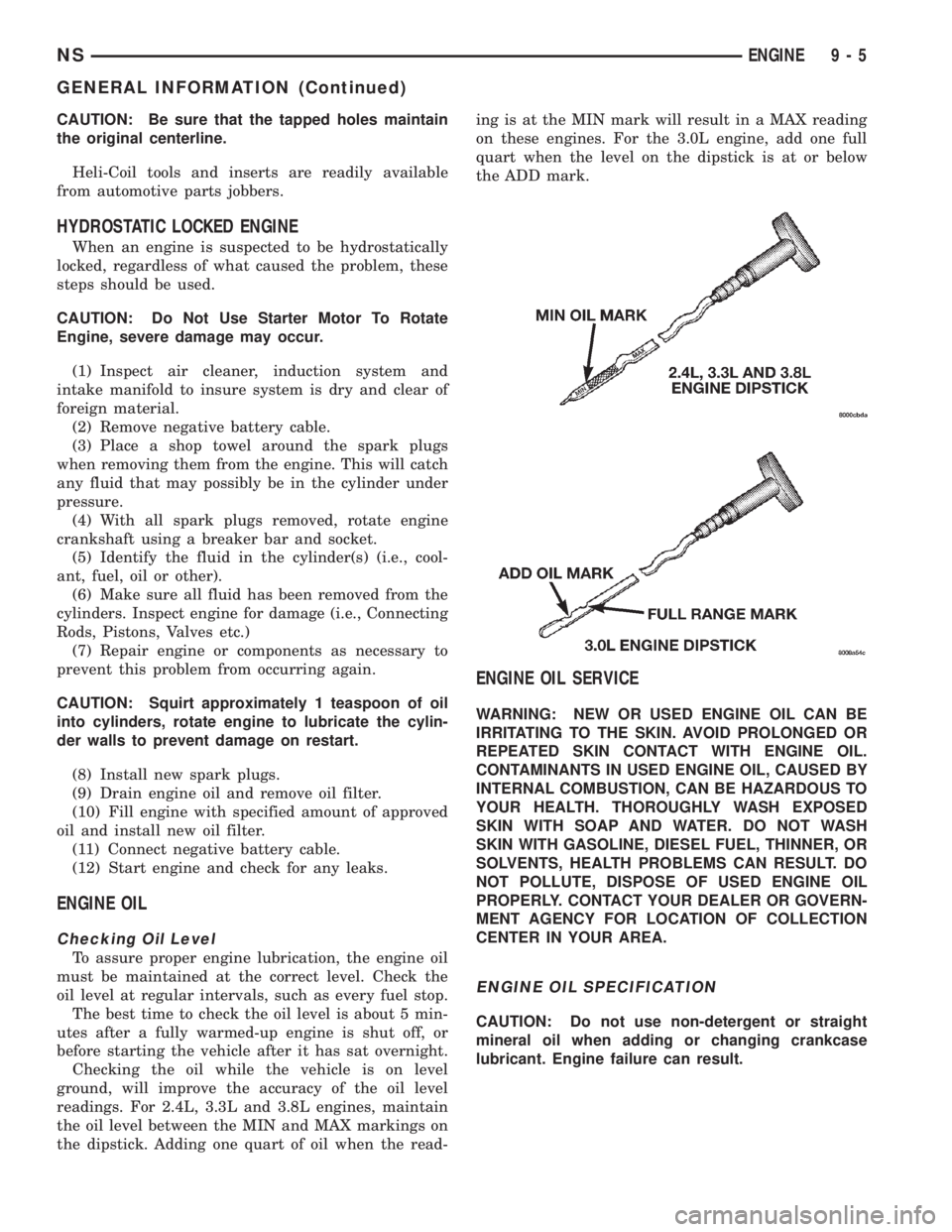
Checking Oil Level
To assure proper engine lubrication, the engine oil
must be maintained at the correct level. Check the
oil level at regular intervals, such as every fuel stop.
The best time to check the oil level is about 5 min-
utes after a fully warmed-up engine is shut off, or
before starting the vehicle after it has sat overnight.
Checking the oil while the vehicle is on level
ground, will improve the accuracy of the oil level
readings. For 2.4L, 3.3L and 3.8L engines, maintain
the oil level between the MIN and MAX markings on
the dipstick. Adding one quart of oil when the read-ing is at the MIN mark will result in a MAX reading
on these engines. For the 3.0L engine, add one full
quart when the level on the dipstick is at or below
the ADD mark.
ENGINE OIL SERVICE
WARNING: NEW OR USED ENGINE OIL CAN BE
IRRITATING TO THE SKIN. AVOID PROLONGED OR
REPEATED SKIN CONTACT WITH ENGINE OIL.
CONTAMINANTS IN USED ENGINE OIL, CAUSED BY
INTERNAL COMBUSTION, CAN BE HAZARDOUS TO
YOUR HEALTH. THOROUGHLY WASH EXPOSED
SKIN WITH SOAP AND WATER. DO NOT WASH
SKIN WITH GASOLINE, DIESEL FUEL, THINNER, OR
SOLVENTS, HEALTH PROBLEMS CAN RESULT. DO
NOT POLLUTE, DISPOSE OF USED ENGINE OIL
PROPERLY. CONTACT YOUR DEALER OR GOVERN-
MENT AGENCY FOR LOCATION OF COLLECTION
CENTER IN YOUR AREA.
ENGINE OIL SPECIFICATION
CAUTION: Do not use non-detergent or straight
mineral oil when adding or changing crankcase
lubricant. Engine failure can result.
NSENGINE 9 - 5
GENERAL INFORMATION (Continued)
Page 1833 of 1938

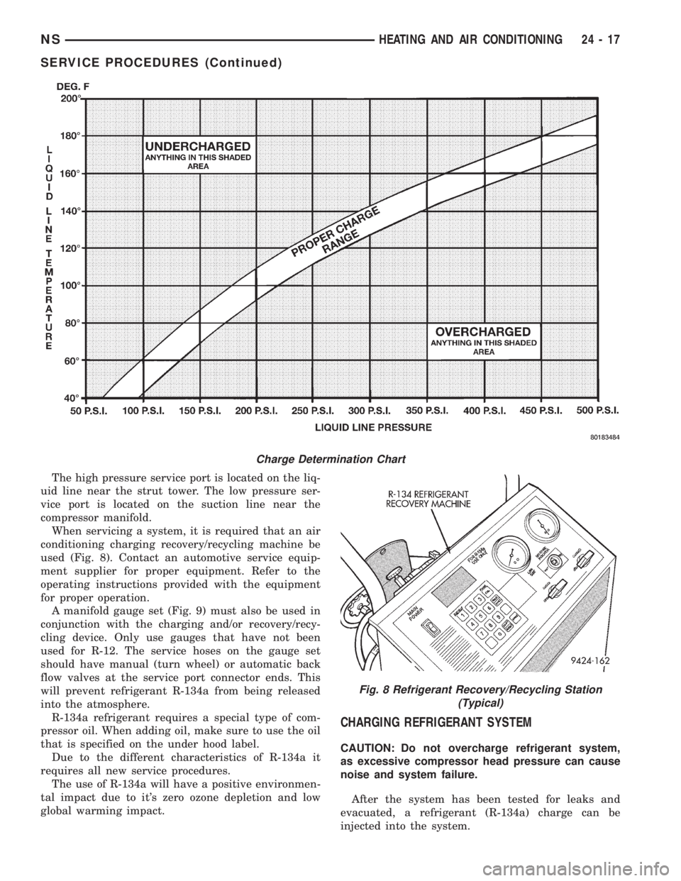
The high pressure service port is located on the liq-
uid line near the strut tower. The low pressure ser-
vice port is located on the suction line near the
compressor manifold.
When servicing a system, it is required that an air
conditioning charging recovery/recycling machine be
used (Fig. 8). Contact an automotive service equip-
ment supplier for proper equipment. Refer to the
operating instructions provided with the equipment
for proper operation.
A manifold gauge set (Fig. 9) must also be used in
conjunction with the charging and/or recovery/recy-
cling device. Only use gauges that have not been
used for R-12. The service hoses on the gauge set
should have manual (turn wheel) or automatic back
flow valves at the service port connector ends. This
will prevent refrigerant R-134a from being released
into the atmosphere.
R-134a refrigerant requires a special type of com-
pressor oil. When adding oil, make sure to use the oil
that is specified on the under hood label.
Due to the different characteristics of R-134a it
requires all new service procedures.
The use of R-134a will have a positive environmen-
tal impact due to it's zero ozone depletion and low
global warming impact.
CHARGING REFRIGERANT SYSTEM
CAUTION: Do not overcharge refrigerant system,
as excessive compressor head pressure can cause
noise and system failure.
After the system has been tested for leaks and
evacuated, a refrigerant (R-134a) charge can be
injected into the system.
Charge Determination Chart
Fig. 8 Refrigerant Recovery/Recycling Station
(Typical)
NSHEATING AND AIR CONDITIONING 24 - 17
SERVICE PROCEDURES (Continued)
Page 1882 of 1938

SERVICE PROCEDURES
R-134a REFRIGERANT
This vehicle uses a new type of refrigerant called
R-134a. It is a non-toxic, non-flammable, clear color-
less liquefied gas.
R-134a refrigerant is not compatible with R-12
refrigerant in an air conditioning system. Even a
small amount of R-12 in a R-134a system could cause
compressor failure, refrigerant oil to sludge and/or
poor performance.Never add any other type of
refrigerant to a system designed to use R-134a
refrigerant. System failure will occur.
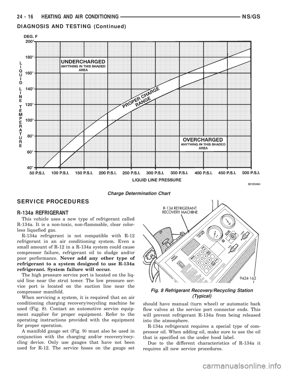
The high pressure service port is located on the liq-
uid line near the strut tower. The low pressure ser-
vice port is located on the suction line near the
compressor manifold.
When servicing a system, it is required that an air
conditioning charging recovery/recycling machine be
used (Fig. 8). Contact an automotive service equip-
ment supplier for proper equipment. Refer to the
operating instructions provided with the equipment
for proper operation.
A manifold gauge set (Fig. 9) must also be used in
conjunction with the charging and/or recovery/recy-
cling device. Only use gauges that have not been
used for R-12. The service hoses on the gauge setshould have manual (turn wheel) or automatic back
flow valves at the service port connector ends. This
will prevent refrigerant R-134a from being released
into the atmosphere.
R-134a refrigerant requires a special type of com-
pressor oil. When adding oil, make sure to use the oil
that is specified on the under hood label.
Due to the different characteristics of R-134a it
requires all new service procedures.
Charge Determination Chart
Fig. 8 Refrigerant Recovery/Recycling Station
(Typical)
24 - 16 HEATING AND AIR CONDITIONINGNS/GS
DIAGNOSIS AND TESTING (Continued)