1996 CHRYSLER VOYAGER transmission
[x] Cancel search: transmissionPage 995 of 1938

CONNECTOR/GROUND LOCATIONS
For items not shown in this section a N/S is placed
in the Fig. column.
Component/
GroundColor Location Fig.
A/C
Compressor
ClutchBK Top of A/C
Compressor5, 6, 7,
8, 9
A/C-Heater
Control Module
C1NAT Rear of Control 11
A/C-Heater
Control Module
C2BK Rear of Control 11
A/C Pressure
TransducerGY RT Side Cowl 3
A/C Zone Door
ActuatorNAT LT Side of
HVAC15
Airbag Control
Module C1YL Rear of I.P.
Center Stack12
Airbag Contol
Module C2BK Rear of I.P.
Center Stack12
All Wheel Drive
SolenoidBK Near Fuel Tank 20
Ambient
Temperature
SensorGY On Radiator
Closure Panel4
Ash Receiver
LampRD At Lamp 10
Automatic
Day/Night MirrorBK At Mirror 17
B01 BK RT Kick Panel 18
B02 BK RT Kick Panel 18
B03 BK LT Kick Panel 18
B09 BK Under Seat 16
B17 BK LT Quarter
Panel21
B23 BK RT of Steering
Column13
B33 BK LT Frame Rail 2
B56 BK Under Seat 16
B70 LT/GY LT Frame Rail 2
B75 BL Bottom of RT
B-Pillar14
B98 BK Rear of RT Tail
LampN/SComponent/
GroundColor Location Fig.
B99 BK Rear of LT Tail
LampN/S
B120 BK LT Kick Panel N/S
Backup Lamp
Switch (M/T)BK On
Transmission5, 6, 8
Blend Door
ActuatorNAT LT Side of
HVAC15
Body Control
Module C1NAT On Junction
Block12
Body Control
Module C2NAT On Junction
Block12
Brake Pressure
SwitchBK On Master
Cylinder2
C19 At Top Center
of Windshield17
C20 Bottom of RT
B-PillarN/S
Camshaft
Position Sensor
2.4LBK Rear of
Cylinder Head6, 7
Camshaft
Position Sensor
3.3L, 3.8LBK RT Side of
Engine9
Center Dome
LampBK At Lamp N/S
CHMSL RD Rear of CHMSL 23
Clockspring C1 YL Rear of
Clockspring11
Clockspring C2 NAT Rear of
Clockspring11
Clutch Switch BK Top of Clutch
Pedal13
Controller
Anti-Lock BrakeBK LT Side of
Engine
CompartmentN/S
Crankshaft
Position SensorBK Rear of Engine 5, 6, 7,
9
D01 BK On Kick Panel 19
D02 BK On Kick Panel 19
Data Link
ConnectorBK LT of Steering
Column12
NS/GS8W - 90 CONNECTOR/GROUND LOCATIONS 8W - 90 - 31
DESCRIPTION AND OPERATION (Continued)
Page 998 of 1938

Component/
GroundColor Location Fig.
Left Rear
Reading LampGY At Lamp 17
Left Rear
Sliding Door
ContactBK LT B-Pillar 14
Left Rear
Sliding Door
Lock MotorBK At Motor N/S
Left Rear
SpeakerBK At Speaker 21
Left Rear Vent
MotorNAT At Motor 21
Left Rear Wheel
Speed SensorGY Center Rear of
Floor Pan16
Left Repeater
LampGY At Lamp N/S
Left Speed
Control SwitchLeft Side of
Steering Wheel
Pad11
Left Stop/Turn
Signal RelayBK LT Quarter
PanelN/S
Left Visor/Vanity
LampBK At Lamp 17
License Lamp GY At Lamps 23
Liftgate Ajar
SwitchBK At Latch 23
Liftgate
Arm/Disarm
SwitchGY At Key Cylinder 23
Liftgate Lock
MotorBK At Motor 23
LJ01 BK LT Quarter
Panel21
Low Note Horn BK LT Frame Rail 4
Low Washer
Fluid Level
SensorBK Bottom of
Reservior4
MAP Sensor
2.4LBK On Intake N/S
MAP Sensor
3.3L, 3.8LBK Near Throttle
Body9
Memort
Seat/Mirror
ModuleBK RT Front of
Floor Pan16
Memory Set
SwitchBL At Switch 19Component/
GroundColor Location Fig.
Message Center BL Rear of
Message
Center11
Mode Door
ActuatorBK LT Side of
HVAC15
Multi Function
SwitchBK Rear of Switch 11
Name Brand
Speaker RelayLT/GY LT of Steering
ColumnN/S
Output Shaft
Speed SensorGY Front of
Transmission7, 9
Overhead
ConsoleRD Front of
Console17
P18 GY RT of Steering
Column12
P30 BK RT Side of
HVAC10
P34 GY RT of Steering
Column12
P50 NAT Right Side of
HVAC Taped to
Harness10
Park Brake
SwitchNAT Top of Park
BrakeN/S
Park/Neutral
Positon SwitchBK Front of
TransmissionN/S
Passenger
AirbagYL Rear of Airbag 11
PDC C1 NAT Bottom of PDC 2
PDC C2 OR Bottom of PDC 2
PDC C3 DK/
GNBottom of PDC 2
PDC C4 BK Bottom of PDC 2
PDC C5 LT/GY Bottom of PDC 2
PDC C6 LT/GN Bottom of PDC 3
PDC C7 LT/GY Bottom of PDC 3
PDC C8 BL Bottom of PDC 3
Power Folding
Mirror SwitchBK At Switch N/S
Power Mirror
SwitchBK Rear of Switch 11
Power Steering
Pressure SwitchBK RT Side of
Engine
CompartmentN/S
8W - 90 - 34 8W - 90 CONNECTOR/GROUND LOCATIONSNS/GS
DESCRIPTION AND OPERATION (Continued)
Page 1000 of 1938

Component/
GroundColor Location Fig.
Right Rear
Sliding Door
ContactBK RT B-Pillar 14
Right Rear
Sliding Door
Lock MotorBK At Motor N/S
Right Rear
SpeakerBK At Speaker 22
Right Rear Vent
MotorNAT At Motor 22
Right Rear
Wheel Speed
SensorGY Center Rear of
Floor Pan16
Right Repeater
LampGY At Lamp N/S
Right Speed
Control SwitchRight Side of
Steering Wheel
Pad11
Right Stop/Turn
Signal RelayBK LT Quarter
PanelN/S
Right Visor/
Vanity LampBK At Lamp 17
S02 BK Under Seat N/S
Seat Belt Switch BK RT B-Pillar N/S
Sentry Key
Immobilizer
ModuleBK Near Steering
Column at
Module11
Stop Lamp
SwitchGY Top of Brake
Pedal12
T05 BK LT Quarter
PanelN/S
T08 BK RT Quarter
PanelN/SComponent/
GroundColor Location Fig.
Throttle Position
SensorNAT On Throttle
Body5, 6, 7,
8, 9
Trailer Tow
ConnectorBK LT Quarter
PanelN/S
Transmission
Control ModuleBK RT Fender Side
Shield3
Transmission
Range SensorBK Top of
Transmission7. 9
Transmission
Control
SolenoidsBK Front of
Transmission7, 9
Turbine Speed
SensorGY Front of
Transmission7, 9
Turn Signal/
Hazard SwitchBK Part of
Multifunction
Switch11
Upstream
Heated Oxygen
SensorGY Rear of Engine 5, 6, 7,
8, 9
Vehicle Speed
Control ServoBK LT Rear of
Engine
Compartment5, 6, 7,
8, 9
Vehicle Speed
SensorBK Rear of
Transmission5, 6, 8
Windshield
Wiper SwitchBK Part of
Multifunction
Switch11
Wiper Module BK LT Side of
Engine2
8W - 90 - 36 8W - 90 CONNECTOR/GROUND LOCATIONSNS/GS
DESCRIPTION AND OPERATION (Continued)
Page 1025 of 1938
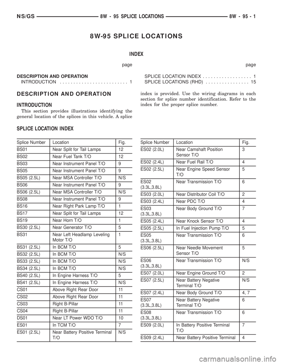
8W-95 SPLICE LOCATIONS
INDEX
page page
DESCRIPTION AND OPERATION
INTRODUCTION......................... 1SPLICE LOCATION INDEX.................. 1
SPLICE LOCATIONS (RHD)................ 15
DESCRIPTION AND OPERATION
INTRODUCTION
This section provides illustrations identifying the
general location of the splices in this vehicle. A spliceindex is provided. Use the wiring diagrams in each
section for splice number identification. Refer to the
index for the proper splice number.
SPLICE LOCATION INDEX
Splice Number Location Fig.
BS01 Near Split for Tail Lamps 12
BS02 Near Fuel Tank T/O 12
BS03 Near Instrument Panel T/O 9
BS05 Near Instrument Panel T/O 9
BS05 (2.5L) Near MSA Controller T/O N/S
BS06 Near Instrument Panel T/O 9
BS06 (2.5L) Near MSA Controller T/O N/S
BS08 Near Instrument Panel T/O 9
BS16 Near Right Park Lamp T/O 1
BS17 Near Split for Tail Lamps 12
BS19 Near Horn T/O 1
BS30 (2.5L) Near Generator T/O 5
BS31 Near Left Headlamp Leveling
Motor T/O1
BS31 (2.5L) In BCM T/O 5
BS32 (2.5L) In BCM T/O N/S
BS33 (2.5L) In BCM T/O N/S
BS34 (2.5L) In BCM T/O N/S
BS40 (2.5L) In Engine Harness T/O 5
BS41 (2.5L) In Engine Harness T/O N/S
CS01 Above Right Rear Door 11
CS02 Above Right Rear Door 11
CS03 Right B-Pillar 11
CS04 Right B-Pillar 11
DS01 Near LT Power WDO T/O 10
ES01 In TCM T/O 7
ES01 (2.5L) Near Battery Positive Terminal
T/ON/SSplice Number Location Fig.
ES02 (2.0L) Near Camshaft Position
Sensor T/O3
ES02 (2.4L) Near Fuel Rail T/O 4
ES02 (2.5L) Near Engine Speed Sensor
T/O5
ES02
(3.3L,3.8L)Near Transmission T/O 6
ES03 (2.0L) Near Distributor Coil T/O 2
ES03 (2.4L) Near PDC T/O 4
ES03
(3.3L,3.8L)Near Body Ground T/O 7
ES05 (2.4L) Near Knock Sensor T/O 4
ES05 (2.5L) In Fuel Injection Pump T/O 5
ES05
(3.3L,3.8L)Near Transmission T/O 6
ES06 (2.5L) Near Needle Movement
Sensor T/O5
ES06
(3.3L,3.8L)Near Transmission T/O N/S
ES07 (2.0L) Near Engine Ground T/O 2
ES07 (2.5L) Near Battery Negative
Terminal T/ON/S
ES07 (2.4L) Near Body Ground T/O 4, 7
ES07
(3.3L,3.8L)Near Battery Negative
Terminal T/O6
ES08
(3.3L,3.8L)Near Transmission T/O 6
ES09 (2.0L) In Battery Positive Terminal
T/O7
ES09 (2.4L) Near Battery Positive Terminal 4
NS/GS8W - 95 SPLICE LOCATIONS 8W - 95 - 1
Page 1026 of 1938
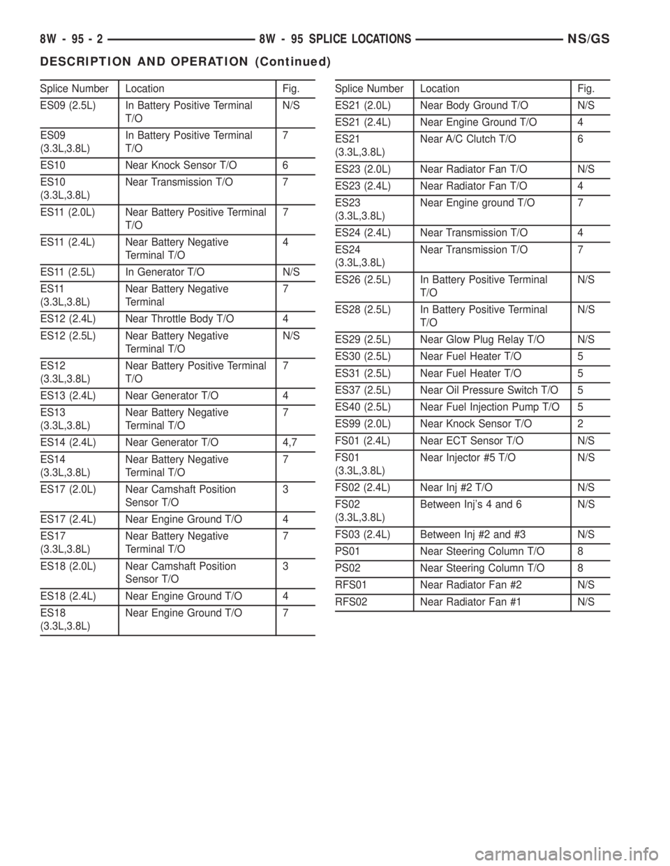
Splice Number Location Fig.
ES09 (2.5L) In Battery Positive Terminal
T/ON/S
ES09
(3.3L,3.8L)In Battery Positive Terminal
T/O7
ES10 Near Knock Sensor T/O 6
ES10
(3.3L,3.8L)Near Transmission T/O 7
ES11 (2.0L) Near Battery Positive Terminal
T/O7
ES11 (2.4L) Near Battery Negative
Terminal T/O4
ES11 (2.5L) In Generator T/O N/S
ES11
(3.3L,3.8L)Near Battery Negative
Terminal7
ES12 (2.4L) Near Throttle Body T/O 4
ES12 (2.5L) Near Battery Negative
Terminal T/ON/S
ES12
(3.3L,3.8L)Near Battery Positive Terminal
T/O7
ES13 (2.4L) Near Generator T/O 4
ES13
(3.3L,3.8L)Near Battery Negative
Terminal T/O7
ES14 (2.4L) Near Generator T/O 4,7
ES14
(3.3L,3.8L)Near Battery Negative
Terminal T/O7
ES17 (2.0L) Near Camshaft Position
Sensor T/O3
ES17 (2.4L) Near Engine Ground T/O 4
ES17
(3.3L,3.8L)Near Battery Negative
Terminal T/O7
ES18 (2.0L) Near Camshaft Position
Sensor T/O3
ES18 (2.4L) Near Engine Ground T/O 4
ES18
(3.3L,3.8L)Near Engine Ground T/O 7Splice Number Location Fig.
ES21 (2.0L) Near Body Ground T/O N/S
ES21 (2.4L) Near Engine Ground T/O 4
ES21
(3.3L,3.8L)Near A/C Clutch T/O 6
ES23 (2.0L) Near Radiator Fan T/O N/S
ES23 (2.4L) Near Radiator Fan T/O 4
ES23
(3.3L,3.8L)Near Engine ground T/O 7
ES24 (2.4L) Near Transmission T/O 4
ES24
(3.3L,3.8L)Near Transmission T/O 7
ES26 (2.5L) In Battery Positive Terminal
T/ON/S
ES28 (2.5L) In Battery Positive Terminal
T/ON/S
ES29 (2.5L) Near Glow Plug Relay T/O N/S
ES30 (2.5L) Near Fuel Heater T/O 5
ES31 (2.5L) Near Fuel Heater T/O 5
ES37 (2.5L) Near Oil Pressure Switch T/O 5
ES40 (2.5L) Near Fuel Injection Pump T/O 5
ES99 (2.0L) Near Knock Sensor T/O 2
FS01 (2.4L) Near ECT Sensor T/O N/S
FS01
(3.3L,3.8L)Near Injector #5 T/O N/S
FS02 (2.4L) Near Inj #2 T/O N/S
FS02
(3.3L,3.8L)Between Inj's 4 and 6 N/S
FS03 (2.4L) Between Inj #2 and #3 N/S
PS01 Near Steering Column T/O 8
PS02 Near Steering Column T/O 8
RFS01 Near Radiator Fan #2 N/S
RFS02 Near Radiator Fan #1 N/S
8W - 95 - 2 8W - 95 SPLICE LOCATIONSNS/GS
DESCRIPTION AND OPERATION (Continued)
Page 1039 of 1938
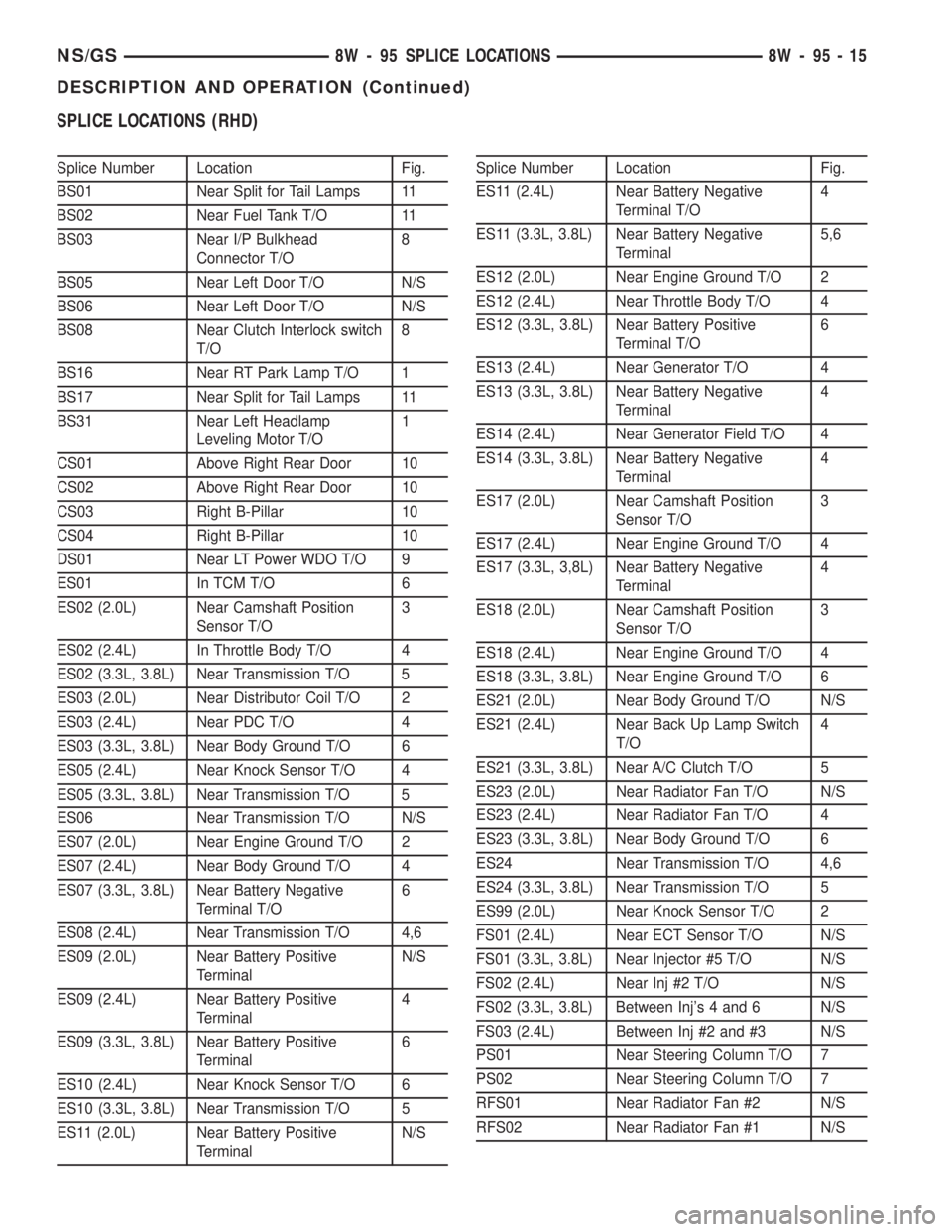
SPLICE LOCATIONS (RHD)
Splice Number Location Fig.
BS01 Near Split for Tail Lamps 11
BS02 Near Fuel Tank T/O 11
BS03 Near I/P Bulkhead
Connector T/O8
BS05 Near Left Door T/O N/S
BS06 Near Left Door T/O N/S
BS08 Near Clutch Interlock switch
T/O8
BS16 Near RT Park Lamp T/O 1
BS17 Near Split for Tail Lamps 11
BS31 Near Left Headlamp
Leveling Motor T/O1
CS01 Above Right Rear Door 10
CS02 Above Right Rear Door 10
CS03 Right B-Pillar 10
CS04 Right B-Pillar 10
DS01 Near LT Power WDO T/O 9
ES01 In TCM T/O 6
ES02 (2.0L) Near Camshaft Position
Sensor T/O3
ES02 (2.4L) In Throttle Body T/O 4
ES02 (3.3L, 3.8L) Near Transmission T/O 5
ES03 (2.0L) Near Distributor Coil T/O 2
ES03 (2.4L) Near PDC T/O 4
ES03 (3.3L, 3.8L) Near Body Ground T/O 6
ES05 (2.4L) Near Knock Sensor T/O 4
ES05 (3.3L, 3.8L) Near Transmission T/O 5
ES06 Near Transmission T/O N/S
ES07 (2.0L) Near Engine Ground T/O 2
ES07 (2.4L) Near Body Ground T/O 4
ES07 (3.3L, 3.8L) Near Battery Negative
Terminal T/O6
ES08 (2.4L) Near Transmission T/O 4,6
ES09 (2.0L) Near Battery Positive
TerminalN/S
ES09 (2.4L) Near Battery Positive
Terminal4
ES09 (3.3L, 3.8L) Near Battery Positive
Terminal6
ES10 (2.4L) Near Knock Sensor T/O 6
ES10 (3.3L, 3.8L) Near Transmission T/O 5
ES11 (2.0L) Near Battery Positive
TerminalN/SSplice Number Location Fig.
ES11 (2.4L) Near Battery Negative
Terminal T/O4
ES11 (3.3L, 3.8L) Near Battery Negative
Terminal5,6
ES12 (2.0L) Near Engine Ground T/O 2
ES12 (2.4L) Near Throttle Body T/O 4
ES12 (3.3L, 3.8L) Near Battery Positive
Terminal T/O6
ES13 (2.4L) Near Generator T/O 4
ES13 (3.3L, 3.8L) Near Battery Negative
Terminal4
ES14 (2.4L) Near Generator Field T/O 4
ES14 (3.3L, 3.8L) Near Battery Negative
Terminal4
ES17 (2.0L) Near Camshaft Position
Sensor T/O3
ES17 (2.4L) Near Engine Ground T/O 4
ES17 (3.3L, 3,8L) Near Battery Negative
Terminal4
ES18 (2.0L) Near Camshaft Position
Sensor T/O3
ES18 (2.4L) Near Engine Ground T/O 4
ES18 (3.3L, 3.8L) Near Engine Ground T/O 6
ES21 (2.0L) Near Body Ground T/O N/S
ES21 (2.4L) Near Back Up Lamp Switch
T/O4
ES21 (3.3L, 3.8L) Near A/C Clutch T/O 5
ES23 (2.0L) Near Radiator Fan T/O N/S
ES23 (2.4L) Near Radiator Fan T/O 4
ES23 (3.3L, 3.8L) Near Body Ground T/O 6
ES24 Near Transmission T/O 4,6
ES24 (3.3L, 3.8L) Near Transmission T/O 5
ES99 (2.0L) Near Knock Sensor T/O 2
FS01 (2.4L) Near ECT Sensor T/O N/S
FS01 (3.3L, 3.8L) Near Injector #5 T/O N/S
FS02 (2.4L) Near Inj #2 T/O N/S
FS02 (3.3L, 3.8L) Between Inj's 4 and 6 N/S
FS03 (2.4L) Between Inj #2 and #3 N/S
PS01 Near Steering Column T/O 7
PS02 Near Steering Column T/O 7
RFS01 Near Radiator Fan #2 N/S
RFS02 Near Radiator Fan #1 N/S
NS/GS8W - 95 SPLICE LOCATIONS 8W - 95 - 15
DESCRIPTION AND OPERATION (Continued)
Page 1053 of 1938
(5) Test resistance of spark plug cables. Refer to
Group 8D, Ignition System.
(6) Test ignition coils primary and secondary resis-
tance. Replace parts as necessary. Refer to Group 8D,
Ignition System.
(7) Check fuel pump pressure at idle and different
RPM ranges. Refer to Group 14, Fuel System for
Specifications.
(8) The air filter elements should be replaced as
specified in Group 0, Lubrication and Maintenance.
(9) Inspect crankcase ventilation system as out-
lined in Group 25, Emission Control Systems.
(10) Road test vehicle as a final test.
HONING CYLINDER BORES
(1) Used carefully, the cylinder bore resizing hone
C-823 equipped with 220 grit stones, is the best tool
for this job. In addition to deglazing, it will reduce
taper and out-of-round as well as removing light
scuffing, scoring or scratches. Usually a few strokes
will clean up a bore and maintain the required lim-
its.
(2) Deglazing of the cylinder walls may be done
using a cylinder surfacing hone, Tool C-3501,
equipped with 280 grit stones, if the cylinder bore is
straight and round. 20-60 strokes depending on the
bore condition, will be sufficient to provide a satisfac-
tory surface. Inspect cylinder walls after each 20
strokes, using a light honing oil.Do not use engine
or transmission oil, mineral spirits or kerosene.
(3) Honing should be done by moving the hone up
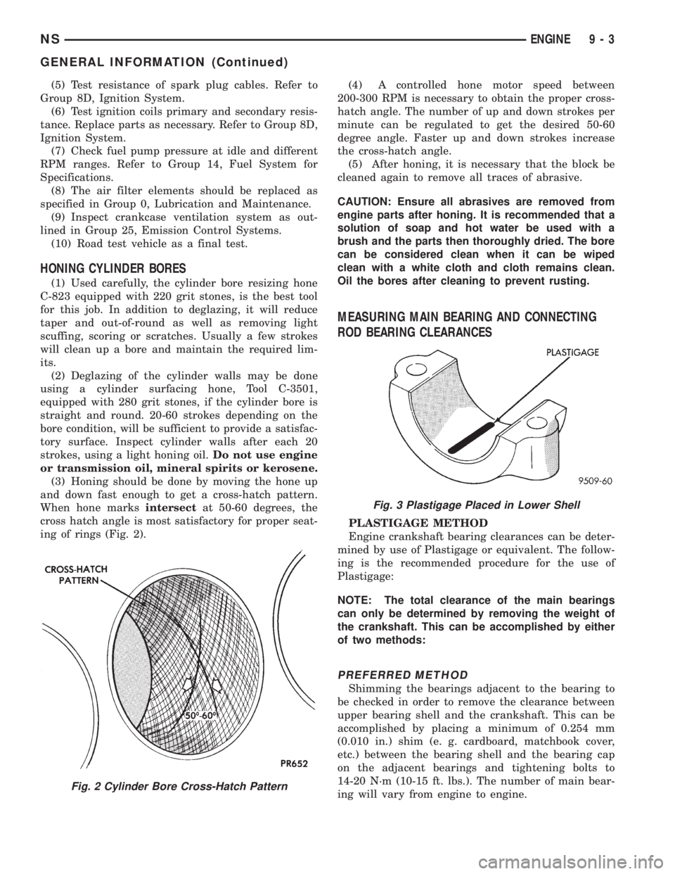
and down fast enough to get a cross-hatch pattern.
When hone marksintersectat 50-60 degrees, the
cross hatch angle is most satisfactory for proper seat-
ing of rings (Fig. 2).(4) A controlled hone motor speed between
200-300 RPM is necessary to obtain the proper cross-
hatch angle. The number of up and down strokes per
minute can be regulated to get the desired 50-60
degree angle. Faster up and down strokes increase
the cross-hatch angle.
(5) After honing, it is necessary that the block be
cleaned again to remove all traces of abrasive.
CAUTION: Ensure all abrasives are removed from
engine parts after honing. It is recommended that a
solution of soap and hot water be used with a
brush and the parts then thoroughly dried. The bore
can be considered clean when it can be wiped
clean with a white cloth and cloth remains clean.
Oil the bores after cleaning to prevent rusting.
MEASURING MAIN BEARING AND CONNECTING
ROD BEARING CLEARANCES
PLASTIGAGE METHOD
Engine crankshaft bearing clearances can be deter-
mined by use of Plastigage or equivalent. The follow-
ing is the recommended procedure for the use of
Plastigage:
NOTE: The total clearance of the main bearings
can only be determined by removing the weight of
the crankshaft. This can be accomplished by either
of two methods:
PREFERRED METHOD
Shimming the bearings adjacent to the bearing to
be checked in order to remove the clearance between
upper bearing shell and the crankshaft. This can be
accomplished by placing a minimum of 0.254 mm
(0.010 in.) shim (e. g. cardboard, matchbook cover,
etc.) between the bearing shell and the bearing cap
on the adjacent bearings and tightening bolts to
14-20 N´m (10-15 ft. lbs.). The number of main bear-
ing will vary from engine to engine.
Fig. 2 Cylinder Bore Cross-Hatch Pattern
Fig. 3 Plastigage Placed in Lower Shell
NSENGINE 9 - 3
GENERAL INFORMATION (Continued)
Page 1059 of 1938
(2) Add an oil soluble dye (use as recommended by
manufacturer). Start the engine and let idle for
approximately 15 minutes. Check the oil dipstick to
make sure the dye is thoroughly mixed as indicated
with a bright yellow color under a black light.
(3) Using a black light, inspect the entire engine
for fluorescent dye, particularly at the suspected area
of oil leak. If the oil leak is found and identified,
repair per service manual instructions.
(4) If dye is not observed, drive the vehicle at var-
ious speeds for approximately 24km (15 miles), and
repeat inspection.
(5)If the oil leak source is not positively
identified at this time, proceed with the air leak
detection test method as follows:
(6) Disconnect the fresh air hose (makeup air) at
the cylinder head cover and plug or cap the nipple on
the cover.
(7) Remove the PCV valve hose from the cylinder
head cover. Cap or plug the PCV valve nipple on the
cover.
(8) Attach an air hose with pressure gauge and
regulator to the dipstick tube.
CAUTION: Do not subject the engine assembly to
more than 20.6 kpa (3 PSI) of test pressure.
(9) Gradually apply air pressure from 1 psi to 2.5
psi maximum while applying soapy water at the sus-
pected source. Adjust the regulator to the suitable
test pressure that provide the best bubbles which
will pinpoint the leak source. If the oil leak is
detected and identified, repair per service manual
procedures.
(10) If the leakage occurs at the rear oil seal area,
refer to the section, Inspection for Rear Seal Area
Leak.
(11) If no leaks are detected, turn off the air sup-
ply and remove the air hose and all plugs and caps.
Install the PCV valve and breather cap hose. Proceed
to next step.
(12) Clean the oil off the suspect oil leak area
using a suitable solvent. Drive the vehicle at various
speeds approximately 24 km (15 miles). Inspect the
engine for signs of an oil leak by using a black light.INSPECTION FOR REAR SEAL AREA LEAKS
Since it is sometimes difficult to determine the
source of an oil leak in the rear seal area of the
engine, a more involved inspection is necessary. The
following steps should be followed to help pinpoint
the source of the leak.
If the leakage occurs at the crankshaft rear oil seal
area:
(1) Disconnect the battery.
(2) Raise the vehicle.
(3) Remove torque converter or clutch housing
cover and inspect rear of block for evidence of oil.
Use a black light to check for the oil leak. If a leak is
present in this area remove transmission for further
inspection.
(a) Circular spray pattern generally indicates
seal leakage or crankshaft damage.
(b) Where leakage tends to run straight down,
possible causes are a porous block, oil galley cup
plug, bedplate to cylinder block mating surfaces
and seal bore. See proper repair procedures for
these items.
(4) If no leaks are detected, pressurized the crank-
case as outlined in the, Inspection (Engine oil Leaks
in general)
CAUTION: Do not exceed 20.6 kPa (3 psi).
(5) If the leak is not detected, very slowly turn the
crankshaft and watch for leakage. If a leak is
detected between the crankshaft and seal while
slowly turning the crankshaft, it is possible the
crankshaft seal surface is damaged. The seal area on
the crankshaft could have minor nicks or scratches
that can be polished out with emery cloth.
CAUTION: Use extreme caution when crankshaft
polishing is necessary to remove minor nicks and
scratches. The crankshaft seal flange is especially
machined to complement the function of the rear oil
seal.
(6) For bubbles that remain steady with shaft
rotation, no further inspection can be done until dis-
assembled.
(7) After the oil leak root cause and appropriate
corrective action have been identified. Refer to Rear
Crankshaft Seals, for proper replacement procedures.
NSENGINE 9 - 9
DIAGNOSIS AND TESTING (Continued)