1996 CHRYSLER VOYAGER child lock
[x] Cancel search: child lockPage 1739 of 1938

SEATS
INDEX
page page
REMOVAL AND INSTALLATION
ARM REST.............................. 9
BENCH SEAT BACK COVER................ 9
BENCH SEAT BACK HINGE COVERS........ 10
BENCH SEAT BACK HINGE................. 9
BENCH SEAT RISER ± FIRST REAR......... 11
BENCH SEAT RISER ± SECOND REAR....... 11
BENCH SEAT TRACK ± SECOND REAR...... 11
BUCKET SEAT BACK ASSIST STRAP........ 12
BUCKET SEAT BACK..................... 12
BUCKET SEAT CUSHION PAN.............. 12
BUCKET SEAT CUSHION SIDE COVER....... 13
BUCKET SEAT RECLINER ± MANUAL........ 13
BUCKET SEAT RECLINER ± POWER......... 14
BUCKET SEAT RISER ± MANUAL TRACK..... 14
BUCKET SEAT TRACK FRONT COVER ±
POWER.............................. 15BUCKET SEAT TRACK REAR COVER ±
POWER.............................. 15
BUCKET SEAT TRACK ± MANUAL........... 14
BUCKET SEAT TRACK ± POWER........... 14
CHILD RESTRAINT SEAT MODULE.......... 16
HEAD RESTRAINT SLEEVE................ 18
HEAD RESTRAINT ± BENCH SEAT.......... 16
HEAD RESTRAINT ± BUCKET SEAT......... 17
HEATED SEAT HEATING ELEMENT.......... 18
HEATED SEAT MODULE.................. 18
HEATED SEAT SWITCH................... 19
MECHANICAL LUMBAR HANDLE ASSEMBLY . . 19
PLASTIC GROCERY BAG RETAINER......... 19
POWER SEAT SWITCH................... 20
RECLINER HANDLE ± MANUAL............. 20
UNDER SEAT STORAGE BIN GUIDE......... 21
UNDER SEAT STORAGE BIN LOCK/LATCH.... 21
UNDER SEAT STORAGE BIN............... 20
REMOVAL AND INSTALLATION
ARM REST
REMOVAL
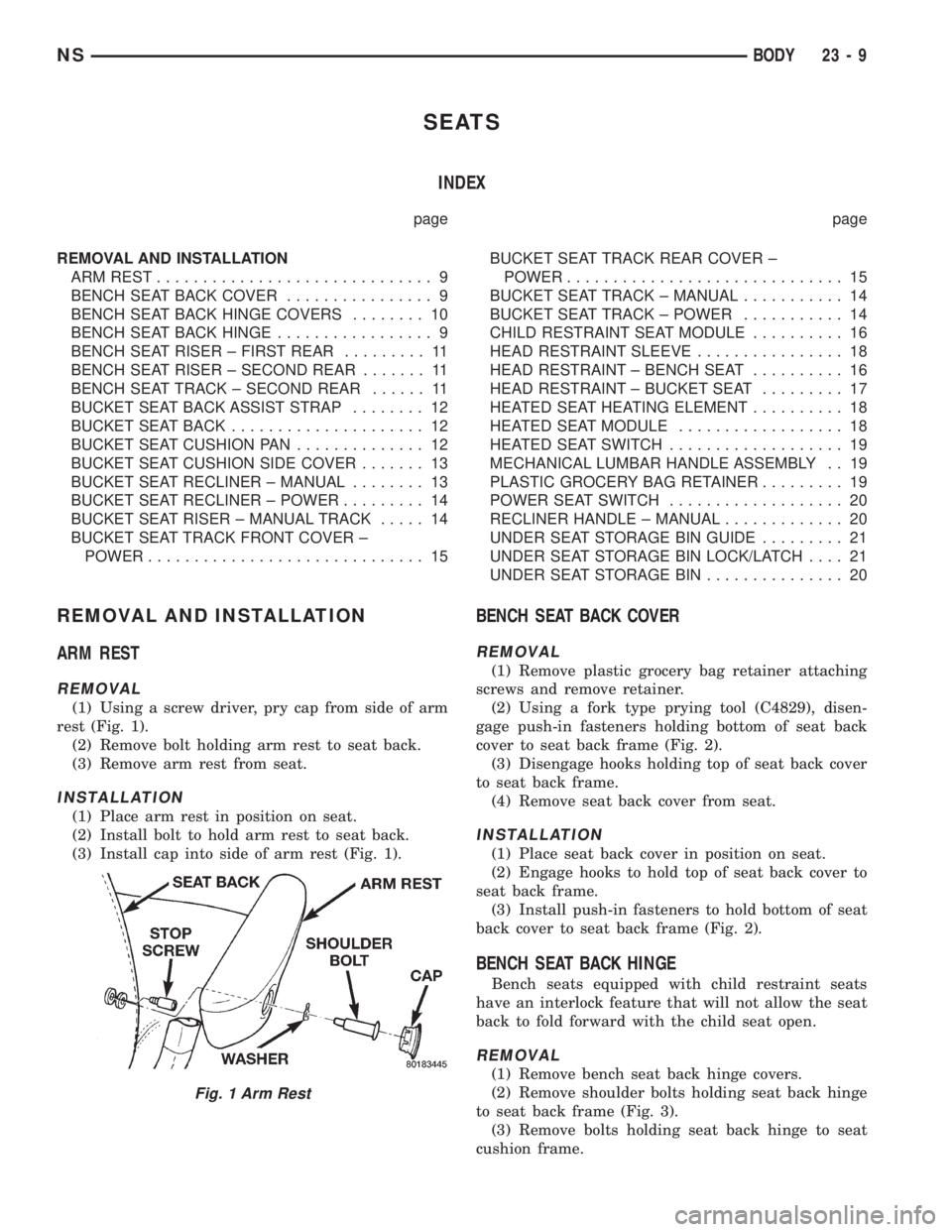
(1) Using a screw driver, pry cap from side of arm
rest (Fig. 1).
(2) Remove bolt holding arm rest to seat back.
(3) Remove arm rest from seat.
INSTALLATION
(1) Place arm rest in position on seat.
(2) Install bolt to hold arm rest to seat back.
(3) Install cap into side of arm rest (Fig. 1).
BENCH SEAT BACK COVER
REMOVAL
(1) Remove plastic grocery bag retainer attaching
screws and remove retainer.
(2) Using a fork type prying tool (C4829), disen-
gage push-in fasteners holding bottom of seat back
cover to seat back frame (Fig. 2).
(3) Disengage hooks holding top of seat back cover
to seat back frame.
(4) Remove seat back cover from seat.
INSTALLATION
(1) Place seat back cover in position on seat.
(2) Engage hooks to hold top of seat back cover to
seat back frame.
(3) Install push-in fasteners to hold bottom of seat
back cover to seat back frame (Fig. 2).
BENCH SEAT BACK HINGE
Bench seats equipped with child restraint seats
have an interlock feature that will not allow the seat
back to fold forward with the child seat open.
REMOVAL
(1) Remove bench seat back hinge covers.
(2) Remove shoulder bolts holding seat back hinge
to seat back frame (Fig. 3).
(3) Remove bolts holding seat back hinge to seat
cushion frame.
Fig. 1 Arm Rest
NSBODY 23 - 9
Page 1746 of 1938

CHILD RESTRAINT SEAT MODULE
REMOVAL
(1) Close child restraint seat.
(2) Remove seat back cover.
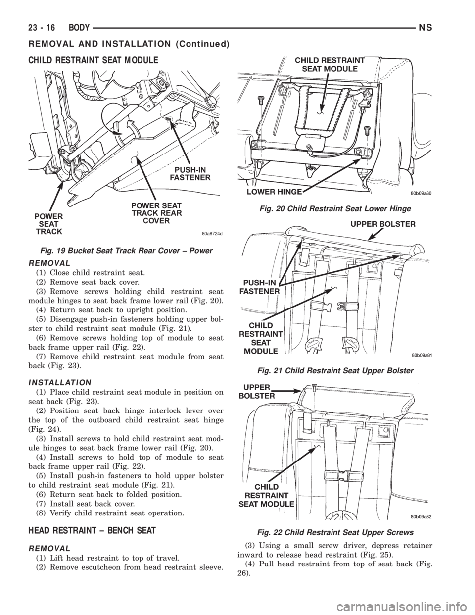
(3) Remove screws holding child restraint seat
module hinges to seat back frame lower rail (Fig. 20).
(4) Return seat back to upright position.
(5) Disengage push-in fasteners holding upper bol-
ster to child restraint seat module (Fig. 21).
(6) Remove screws holding top of module to seat
back frame upper rail (Fig. 22).
(7) Remove child restraint seat module from seat
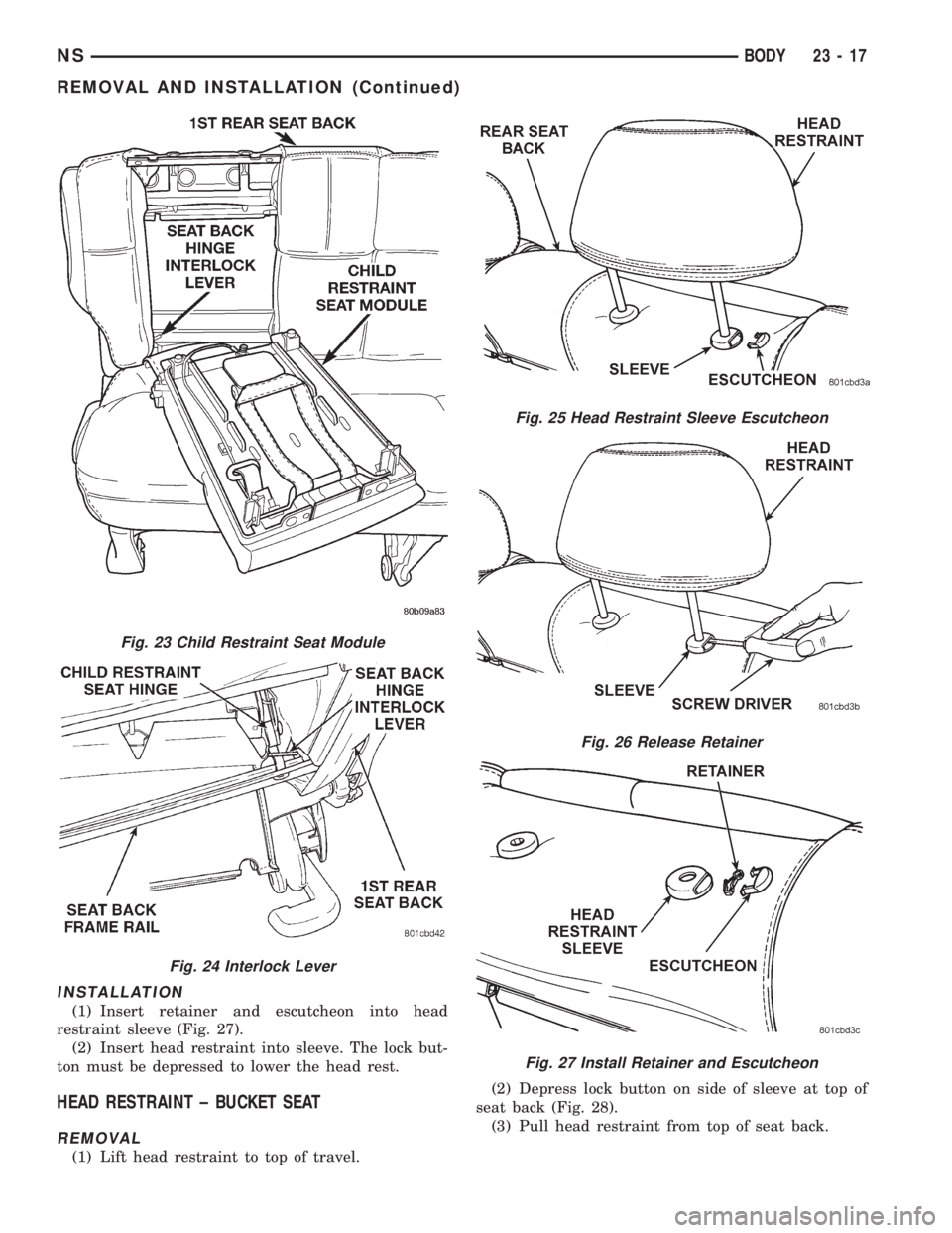
back (Fig. 23).
INSTALLATION
(1) Place child restraint seat module in position on
seat back (Fig. 23).
(2) Position seat back hinge interlock lever over
the top of the outboard child restraint seat hinge
(Fig. 24).
(3) Install screws to hold child restraint seat mod-
ule hinges to seat back frame lower rail (Fig. 20).
(4) Install screws to hold top of module to seat
back frame upper rail (Fig. 22).
(5) Install push-in fasteners to hold upper bolster
to child restraint seat module (Fig. 21).
(6) Return seat back to folded position.
(7) Install seat back cover.
(8) Verify child restraint seat operation.
HEAD RESTRAINT ± BENCH SEAT
REMOVAL
(1) Lift head restraint to top of travel.
(2) Remove escutcheon from head restraint sleeve.(3) Using a small screw driver, depress retainer
inward to release head restraint (Fig. 25).
(4) Pull head restraint from top of seat back (Fig.
26).
Fig. 19 Bucket Seat Track Rear Cover ± Power
Fig. 20 Child Restraint Seat Lower Hinge
Fig. 21 Child Restraint Seat Upper Bolster
Fig. 22 Child Restraint Seat Upper Screws
23 - 16 BODYNS
REMOVAL AND INSTALLATION (Continued)
Page 1747 of 1938

INSTALLATION
(1) Insert retainer and escutcheon into head
restraint sleeve (Fig. 27).
(2) Insert head restraint into sleeve. The lock but-
ton must be depressed to lower the head rest.
HEAD RESTRAINT ± BUCKET SEAT
REMOVAL
(1) Lift head restraint to top of travel.(2) Depress lock button on side of sleeve at top of
seat back (Fig. 28).
(3) Pull head restraint from top of seat back.
Fig. 23 Child Restraint Seat Module
Fig. 24 Interlock Lever
Fig. 25 Head Restraint Sleeve Escutcheon
Fig. 26 Release Retainer
Fig. 27 Install Retainer and Escutcheon
NSBODY 23 - 17
REMOVAL AND INSTALLATION (Continued)
Page 1868 of 1938

SAFETY PRECAUTIONS AND WARNINGS
WARNING: WEAR EYE PROTECTION WHEN SER-
VICING THE AIR CONDITIONING REFRIGERANT
SYSTEM. SERIOUS EYE INJURY CAN RESULT
FROM EYE CONTACT WITH REFRIGERANT. IF EYE
CONTACT IS MADE, SEEK MEDICAL ATTENTION
IMMEDIATELY.
DO NOT EXPOSE REFRIGERANT TO OPEN
FLAME. POISONOUS GAS IS CREATED WHEN
REFRIGERANT IS BURNED. AN ELECTRONIC TYPE
LEAK DETECTOR IS RECOMMENDED.
LARGE AMOUNTS OF REFRIGERANT RELEASED
IN A CLOSED WORK AREA WILL DISPLACE THE
OXYGEN AND CAUSE SUFFOCATION.
THE EVAPORATION RATE OF REFRIGERANT AT
AVERAGE TEMPERATURE AND ALTITUDE IS
EXTREMELY HIGH. AS A RESULT, ANYTHING THAT
COMES IN CONTACT WITH THE REFRIGERANT
WILL FREEZE. ALWAYS PROTECT SKIN OR DELI-
CATE OBJECTS FROM DIRECT CONTACT WITH
REFRIGERANT. R-134a SERVICE EQUIPMENT OR
VEHICLE A/C SYSTEM SHOULD NOT BE PRES-
SURE TESTED OR LEAK TESTED WITH COM-
PRESSED AIR.
SOME MIXTURES OF AIR and R-134a HAVE BEEN
SHOWN TO BE COMBUSTIBLE AT ELEVATED
PRESSURES. THESE MIXTURES ARE POTENTIALLY
DANGEROUS AND MAY RESULT IN FIRE OR
EXPLOSION CAUSING INJURY OR PROPERTY
DAMAGE.
ANTIFREEZE IS AN ETHYLENE GLYCOL BASE
COOLANT AND IS HARMFUL IF SWALLOWED OR
INHALED. SEEK MEDICAL ATTENTION IMMEDI-
ATELY IF SWALLOWED OR INHALED. DO NOT
STORE IN OPEN OR UNMARKED CONTAINERS.
WASH SKIN AND CLOTHING THOROUGHLY AFTER
COMING IN CONTACT WITH ETHYLENE GLYCOL.
KEEP OUT OF REACH OF CHILDREN AND PETS.
DO NOT OPEN A COOLING SYSTEM WHEN THE
ENGINE IS AT RUNNING TEMPERATURE. PER-
SONAL INJURY CAN RESULT.
CAUTION: The engine cooling system is designed
to develop internal pressure of 97 to 123 kPa (14 to
18 psi). Allow the vehicle to cool a minimum of 15
minutes before opening the cooling system. Refer
to Group 7, Cooling System.
DESCRIPTION AND OPERATION
AIR DISTRIBUTION DUCTS
The air distribution ducts for the A/C, Heater,
Defroster, and Second Seating Air Distribution arenot serviceable in vehicle. The procedures for service
of these ducts are covered in Group 8E, Instrument
Panel and Gauges.
The only ducts that are serviceable in the vehicle
are the side window demister ducts and the ducts
that feed the front door outlets for the first rear pas-
senger(s) seating. To service the door ducts refer to
Group 23, Body.
A/C PRESSURE TRANSDUCER
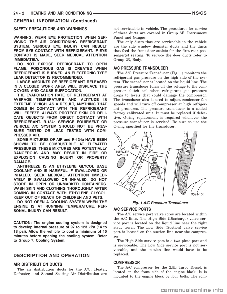
The A/C Pressure Transducer (Fig. 1) monitors the
refrigerant gas pressure on the high side of the sys-
tem. The transducer is located on the liquid line. The
pressure transducer turns off the voltage to the com-
pressor clutch coil when refrigerant gas pressure
drops to levels that could damage the compressor.
The transducer also is used to adjust condenser fan
speeds and will turn off compressor at high refriger-
ant pressures. The pressure transducer is a sealed
factory calibrated unit. It must be replaced if defec-
tive. O-ring replacement is required whenever the
pressure transducer is serviced. Be sure to use the
O-ring specified for the transducer.
A/C SERVICE PORTS
The A/C service port valve cores are located within
the A/C lines. The High Side (Discharge) valve ser-
vice port is located on the liquid line near the right
strut tower. The Low Side (Suction) valve service
port is located on the suction line near the compres-
sor.
The High Side service port is a two piece port and
is serviceable. The Low Side service port is not ser-
viceable, and the suction line would have to be
replaced.
COMPRESSOR
The A/C compressor for the 2.5L Turbo Diesel, is
located on the front side of the engine block. It is
mounted to the engine block by four bolts. The com-
Fig. 1 A/C Pressure Transducer
24 - 2 HEATING AND AIR CONDITIONINGNS/GS
GENERAL INFORMATION (Continued)