1996 ACURA RL KA9 heater
[x] Cancel search: heaterPage 134 of 1954

Troubleshooting
Diagnostic Troubl e Cod e (DTC ) Char t (cont'd )
DTC(MI L indication )
P0139 (63)*2
P014 1 (65 )
P0153 (61)*2
P015 4 (1 )
P015 5 (41 )
P017 1 (46)*
2
P017 2 (46)*2
P017 4 (45)*2
P017 5 (45)*2
P030 0
P0325 (53 )
P033 0 (23 )
Detection Ite m
Secondar y Heate d Oxyge n Senso r(Secondar y H02S ) Slo w Respons e
(Sensor 2 )
Secondar y Heate d Oxyge n
Senso r (Secondar y HO2S ) Heate r
Circui t Malfunctio n (Senso r 2 )
Lef t Primar y Heate d Oxyge n
Senso r (Lef t Primar y HO2S ) Slo w
Respons e (Ban k 2 , Senso r 1 )
Lef t Primar y Heate d Oxyge n
Senso r (Lef t Primar y HO2S )
Heater Syste m Malfunctio n
Left Primar y Heate d Oxyge n
Sensor (Lef t Primar y H02S )
Heate r Circui t Malfunctio n (Ban k
2 , Senso r 1 )
Fue l Syste m To o Lea n [Righ t
Ban k (Ban k 1) ]
Fue l Syste m To o Ric h [Righ t Ban k
(Ban k 1) ]
Fue l Syste m To o Lea n [Lef t Ban k
(Ban k 2) ]
Fue l Syste m To o Ric h [Lef t Ban k
(Ban k 2) ]
Rando m Misfir e
Right Knoc k Senso r (Ban k 1 )Circui t Malfunctio n
Left Knoc k Senso r (Ban k 2 )Circui t Malfunctio n
Probable Caus e
• Secondar y H02 S (Senso r 2 )
• Ope n o r shor t i n Secondar y H02 S
(Senso r 2 ) heate r circui t
• PC M
• Lef t Primar y H02 S (Ban k 2 , Senso r 1 )
• Exhaus t syste m
• Ope n i n Lef t Primar y H02 S (Ban k 2 ,
Senso r 1 ) circui t
• Lef t Primar y H02 S (Ban k 2 , Senso r 1 )
• PC M
• Ope n o r shor t i n Lef t Primar y HO2 S
(Ban k 2 , Senso r 1 ) heate r circui t
• PC M
• Fue l suppl y syste m
• Righ t Primar y H02 S (Ban k 1 , Senso r 1 )
• MA P senso r
• Contaminate d fue l
• Valv e clearanc e
• Exhaus t leakag e
• Fue l suppl y syste m
• Righ t Primar y HO2 S (Ban k 1 , Senso r 1 )
• MA P senso r
• Contaminate d fue l
• Valv e clearanc e
• Fue l suppl y syste m
• Lef t Primar y H02 S (Ban k 2 , Senso r 1 )
• MA P senso r
• Contaminate d fue l• Exhaus t leakag e
• Fue l suppl y syste m
• Lef t Primar y H02 S (Ban k 2 , Senso r 1 )
• MA P senso r
• Contaminate d fue l
• Ignitio n syste m
• Fue l suppl y syste m
• MA P senso r
• EG R syste m
• Contaminate d fue l• Lac k o f fue l
• Ope n o r shor t i n Righ t Knoc k Senso r
(Ban k 1 ) circui t
• Righ t Knoc k Senso r (Ban k 1 )
• PC M
• Ope n o r shor t i n Lef t Knoc k Senso r
(Bank 2 ) circui t• Lef t Knoc k Senso r (Ban k 2 )• PC M
Page
11-5 1
11-5 3
11-57
11-5 7
11-5 7
11-5 7
11-5 9
*2: Thes e DTC s requir e tw o "trips " o r tw o drivin g cycle s unles s th e SC S servic e connecto r i s connected .
11-90
11-91
11-91
11-95
11-95
ProCarManuals.com
Page 141 of 1954

The HDS or the scan tool indicates Diagnostic Trouble Code (DTC) P0133: A slow response problem in the Right
Primary Heated Oxygen Sensor (Right Primary H02S) (Bank 1, Sensor 1) circuit.
The HDS or the scan tool indicates Diagnostic Trouble Code (DTC) P0153: A slow response problem in the Left
Primary Heated Oxygen Sensor (Left Primary HO2S) (Bank 2, Sensor 1) circuit.
Description
By controlling the air/fuel ratio with a Primary HO2S (Sensor 1) and a Secondary HO2S (Sensor 2), the deterioration of the
Primary H02S (Sensor 1) can be evaluated by its feedback period. When the feedback period of the H02S exceeds a certain
value during stable driving conditions, the sensor will be judged as deteriorated. When deterioration has been detected dur-
ing two consecutive trips, the MIL comes on and DTC P0133 or P0153 will be stored.
NOTE: If DTC P2195, P0134, P2297 and/or P0135 are stored at the same time as DTC P0133, troubleshoot those DTCs first,
then troubleshoot DTC P0133. If DTC P2197, P0154, P2298 and/or P0155 are stored at the same time as DTC P0153, trou-
bleshoot those DTCs first, then troubleshoot DTC P0153.
Possible Cause
• Primary HO2S (Sensor 1) Deterioration
• Primary H02S Heater (Sensor 1) Deterioration
• Exhaust system leakage
Primary Heated Oxygen Sensor (HO2S) (Sensor 1)
The Heated Oxygen Sensors (HO2S) detect the oxygen content in the exhaust gas and signal the PCM. In operation, the
PCM receives the signals from the sensor and varies the duration during which fuel is injected. To stabilize the sensor's
output, the sensor has an internal heater. The Right Primary HO2S (Bank 1, Sensor 1) is installed in the right exhaust man-
ifold, and the Left Primary HO2S (Bank 2, Sensor 1) is installed in the left exhaust manifold.ProCarManuals.com
Page 143 of 1954

The HDS or the scan tool indicates Diagnostic Trouble Code (DTC) P0134: Right Primary Heated Oxygen Sensor
(Right Primary HO2S) (Bank 1, Sensor 1) heater system malfunction.
The HDS or the scan tool indicates Diagnostic Trouble Code (DTC) P0154: Left Primary Heated Oxygen Sensor
(Left Primary H02S) (Bank 2, Sensor 1) heater system malfunction.
The MIL has been reported on.
DTC P0134 and/or P0154 are
stored.
Problem verification:
1. Do the PCM Reset Procedure.
2. Start the engine. Hold the
engine at 3,000 rpm with no
load (in Park or neutral) until
the
radiator
fan
comes
on.
Is DTC P0134 and/or P0154
indicated?
YES
Check for an open in the HO2S:
1. Turn the ignition switch OFF.
2.
Disconnect
the
right primary
H02S (Bank 1, Sensor 1) or left
primary HO2S* (Bank2, Sen-
sor 1) connector.
3. Install a jumper wire on the
harness side of the right prima-
ry H02S (Bank 1,Sensor 1) or
left primary H02S*connector
between terminals No. 1 and
No. 2.
4. Turn the ignition switch ON (II).
5. Check the right primary HO2S
(Bank 1, Sensor 1) or left pri-
mary HO2S*(Bank2, Sensorl)
output voltage with the HDS
or the scan tool.
Is there 1.5 V or more?
YES
Check for an open in the wires
(PHO2S line):
1. Turn the ignition switch OFF.
2. Install a jumper wire on the
PCM connector between D19,
orD18*andD22.
3. Turn the ignition switch ON (II).
4. Check the right primary H02S
(Bank 1, Sensor 1) or left pri-
mary H02S* (Bank 2, Sensor 1)
output voltage with the HDS
or the scan tool.
Is there 1.5 V or more?
YES
NO
Intermittent failure, system is OK
at this time. Check for poor con-
nections or loose terminals at
C251, C254 (located at right shock
tower), C119 (right primary H02S
(Bank 1, Sensor 1)) or C126 (left
primary H02S (Bank 2, Sensor 1))*
and
PCM.
Replace the HO2S.
Repair open in the wire between
PCM (019 or D18*) and right pri-
mary HO2S (Bank 1, Sensor 1) or
left primary HO2S* (Bank 2,
Sensor 1).
Substitute a known-good PCM and
recheck. If symptom/indication
goes away, replace the original
PCM.ProCarManuals.com
Page 147 of 1954
![ACURA RL KA9 1996 Service Repair Manual
Fuel Supply System
The HDS or the scan tool indicates Diagnostic Trouble Code (DTC) P0171: The fuel system is too lean [Right
Bank (Bank 1)].
The HDS or the scan tool indicates Diagnostic Trouble ACURA RL KA9 1996 Service Repair Manual
Fuel Supply System
The HDS or the scan tool indicates Diagnostic Trouble Code (DTC) P0171: The fuel system is too lean [Right
Bank (Bank 1)].
The HDS or the scan tool indicates Diagnostic Trouble](/manual-img/32/56992/w960_56992-146.png)
Fuel Supply System
The HDS or the scan tool indicates Diagnostic Trouble Code (DTC) P0171: The fuel system is too lean [Right
Bank (Bank 1)].
The HDS or the scan tool indicates Diagnostic Trouble Code (DTC) P0172: The fuel system is too rich [Right
Bank (Bank 1)].
The HDS or the scan tool indicates Diagnostic Trouble Code (DTC) P0174: The fuel system is too lean [Left Bank
(Bank 2)].
The HDS or the scan tool indicates Diagnostic Trouble Code (DTC) P0175: The fuel system is too rich [Left Bank
(Bank 2)].
Description
By monitoring the Long Term Fuel Trim, long term malfunctions in the fuel system will be detected.
If a
malfunction
has
been detected
during
two
consecutive
trips,
the MIL
will
come
on and DTC
P0171,
P0172, P0174
and/or P0175 will be stored.
NOTE: If some of the DTCs listed below are stored at the same time as DTC P0171, P0172, P0174 and/or P0175, trou-
bleshoot those DTCs first, then troubleshoot DTC P0171, P0172, P0174 and/or P0175.
P0107, P0108, P1128, P1129: MAP Sensor
P0135: Right Primary HO2S Heater (Bank 1, Sensor 1)
P0137, P0138: Secondary HO2S (Sensor 2)
P0141: Secondary HO2S Heater (Sensor 2)
P0155: Left Primary H02S Heater (Bank 2, Sensor 1)
P0401: EGR Flow Insufficient
P0404: EGR Valve Lift Insufficient
P0406: EGR Valve Position Sensor High Voltage
Possible Cause
Fuel Pump insufficient flow/pressure
Fuel Feed Line clogged, leaking
Fuel Pressure Regulator stuck open
Fuel Filter clogged
Injector clogged, air inclusion
Gasoline doesn't meet Owner's Manual spec.
Primary H02S (Sensor 1) deteriorated
EGR System insufficient flow
Exhaust leak
Fuel Pressure Regulator clogged, stuck closed
Fuel Return Pipe clogged
Injector leaking
Gasoline doesn't meet Owner's Manual spec.
Primary HO2S (Sensor 1) deteriorated
EGR System malfunction (too much flow)
EVAP Canister Purge Valve leaking, stuck opened
(cont'd)ProCarManuals.com
Page 207 of 1954

Front Seat
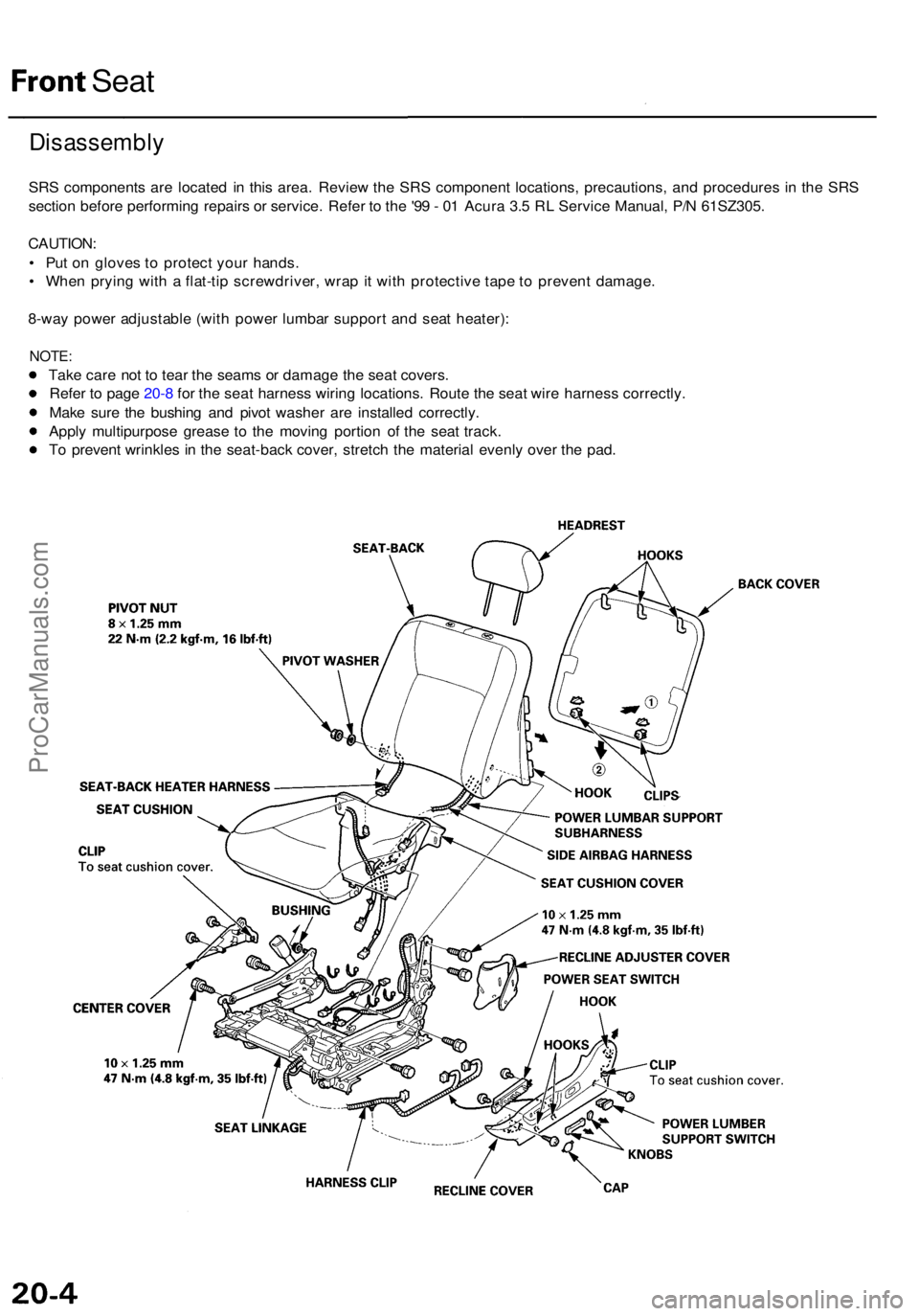
Disassembl y
SRS component s ar e locate d i n thi s area . Revie w th e SR S componen t locations , precautions , an d procedure s i n th e SR S
sectio n befor e performin g repair s o r service . Refe r t o th e
'99 - 0 1 Acur a 3. 5 R L Servic e Manual , P/ N 61SZ305 .
CAUTION :
• Pu t o n glove s t o protec t you r hands .
• Whe n pryin g wit h a flat-ti p screwdriver , wra p it wit h protectiv e tap e t o preven t damage .
8-wa y powe r adjustabl e (wit h powe r lumba r suppor t an d sea t heater) :
NOTE:
Take car e no t t o tea r th e seam s o r damag e th e sea t covers .
Refe r t o pag e 20- 8 fo r th e sea t harnes s wirin g locations . Rout e th e sea t wir e harnes s correctly .
Mak e sur e th e bushin g an d pivo t washe r ar e installe d correctly .
Appl y multipurpos e greas e t o th e movin g portio n o f th e sea t track .
T o preven t wrinkle s i n th e seat-bac k cover , stretc h th e materia l evenl y ove r th e pad .
ProCarManuals.com
Page 213 of 1954

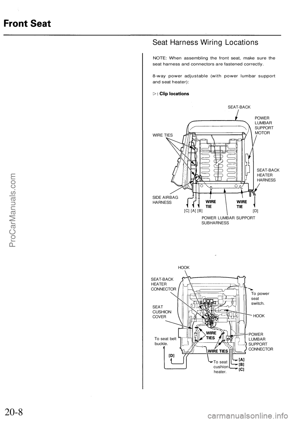
Seat Harness Wiring Locations
NOTE: When assembling the front seat, make sure the
seat harness and connectors are fastened correctly.
8-way power adjustable (with power lumbar support
and seat heater):
SEAT-BACK
WIRE TIES
SIDE AIRBAG
HARNESS
POWER
LUMBAR
SUPPORT
MOTOR
SEAT-BACK
HEATER
HARNESS
[C] [A] [B]
[D]
POWER LUMBAR SUPPORT
SUBHARNESS
HOOK
SEAT
CUSHION
COVER
To seat belt
buckle.
To power
seat
switch.
HOOK
POWER
LUMBAR
SUPPORT
CONNECTOR
To seat
cushion
heater.
20-8
SEAT-BACK
HEATER
CONNECTORProCarManuals.com
Page 488 of 1954

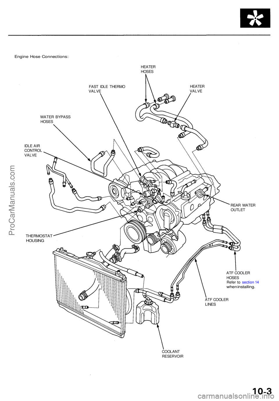
Engine Hos e Connections :
HEATERHOSES
FAS T IDL E THERM O
VALV E
HEATE RVALVE
WATE R BYPAS S
HOSE S
IDL E AI R
CONTRO L
VALV E
THERMOSTA THOUSING
REAR WATE R
OUTLE T
AT F COOLE R
HOSE S
Refe r t o sectio n 1 4
whe n installing .
ATF COOLE RLINES
COOLAN TRESERVOI R
ProCarManuals.com
Page 561 of 1954

PGM-FI System
How to Set Readiness Codes (cont'd)
HO2S Monitor
NOTE:
• Do not turn the ignition switch OFF.
• When the battery negative cable is disconnected, all
readiness codes are cleared.
Required condition ('96 - 97 models):
• Ambient temperature between 32 - 95°F (0 - 35°C).
• Altitude below 2,400 m (7,874 ft.).
Required condition ('98 - 01 models):
Ambient temperature between 20 - 95°F (-7 - 35°C).
1. Connect the scan tool to the Data Link Connector
(DLC).
2. Start the engine, and hold it at 3,000 rpm with no
load (in Park or neutral) until the radiator fan comes
on.
3. Let the engine idle for 5 seconds.
4. Drive at a steady speed between 50 - 62 mph (80 -
100 km/h) for about 2 minutes.
5. With the A/T in D4 position, decelerate from 62 mph
(100 km/h) by completely releasing the throttle for
at least 5 seconds. If the engine is stopped during
this procedure, go to step 4 and do the procedure
again.
6. Check for the readiness code with the scan tool.
HO2S Heater Monitor
NOTE: When the battery negative cable is disconnected,
all readiness codes are cleared.
1. Connect the scan tool to the Data Link Connector
(DLC).
2. Start the engine, and let the engine idle for 10 min-
utes.
3. Check for the readiness code with the scan tool.ProCarManuals.com