Page 583 of 1954

PGM-FI Syste m
Primar y Heate d Oxyge n Senso r (HO2S ) (Senso r 1 )
Th e Heate d Oxyge n Sensor s (HO2S ) detec t th e oxyge n conten t i n th e exhaus t ga s an d signa l th e PCM . I n operation , th e
PC M receive s th e signal s fro m th e senso r an d varie s th e duratio n durin g whic h fue l i s injected . T o stabiliz e th e sensor' s
output, th e senso r ha s a n interna l heater . Th e Righ t Primar y HO2 S (Ban k 1 , Senso r 1 ) i s installe d in th e righ t exhaus t man -
ifold, an d th e Lef t Primar y HO2 S (Ban k 2 , Senso r 1 ) i s installe d in th e lef t exhaus t manifold .
ZIRCONIAELEMENT
SENSORTERMINA L
®e
VOLTAG E (V )
HEATE R
STOICHIOMETRI CAIR-FUEL RATI O
HEATE RTERMINA LRICHAIR -FUE LRATI O
LEAN
The sca n too l indicate s Diagnosti c Troubl e Cod e (DTC ) P0131 : A lo w voltag e proble m in th e Righ t Primar y
Heated Oxyge n Senso r (HO2S ) (Ban k 1 , Senso r 1 ) circuit .
The sca n too l indicate s Diagnosti c Troubl e Cod e (DTC ) P0151 : A lo w voltag e proble m in th e Lef t Primar y
Heated Oxyge n Senso r (HO2S ) (Ban k 2 , Senso r 1 ) circuit .
— Th e MI L ha s bee n reporte d on .
— DT C P013 1 and/o r P015 1 ar e
stored .
Doe s th e voltag e sta y a t 0. 5 V
o r less ?
Is i t normal ?
(T o pag e 11-85 )
NO
Intermitten t failure , syste m is O K
a t thi s time . Chec k fo r poo r con -
nection s o r loos e wire s a t C251 ,
C25 4 (locate d a t lef t shoc k tower )
C11 9 (righ t primar y HO2 S (Ban k
1 , Senso r 1) ) o r C12 6 (lef t prima -
r y HO2 S (Ban k 2 , Senso r 1)) * an d
PCM .
Repai r fue l suppl y system .
*: P015 1
NO
YE S
Chec k th e fue l pressure .
YES
Proble m verification :
1 . D o th e PC M Rese t Procedure .
2 . Star t th e engine . Hol d th e
engin e a t 3,00 0 rp m wit h n oloa d (in Par k or neutral ) untilthe radiato r fa n come s on .
3 . Test-driv e wit h th e transmis -
sion in position .
4 . Chec k th e righ t primar y HO2 S
(Ban k 1 , Senso r 1 ) o r lef t pri -
mar y HO2S * (Ban k 2 , Senso r
1 ) outpu t voltag e wit h th e sca n
too l durin g acceleratio n usin g
wid e ope n throttle .
ProCarManuals.com
Page 592 of 1954

Fuel Supply System
Description
By monitoring the Long Term Fuel Trim, long term malfunctions in the fuel system will be detected.
If a
malfunction
has
been detected during
two
consecutive
trips,
the MIL
will
come
on and DTC
P0171, P0172,
P0174
and/or P0175 will be stored.
NOTE: If some of the DTCs listed below are stored at the same time as DTC P0171, P0172, P0174 and/or P0175, trou-
bleshoot those DTCs first, then troubleshoot DTC P0171, P0172, P0174 and/or P0175.
P0106*1, P0107, P0108, P1128*2, P1129*2: MAP Sensor
P0135: Right Primary HO2S Heater (Bank 1, Sensor 1)
P0137, P0138: Secondary HO2S (Sensor 2)
P0141: Secondary HO2S Heater (Sensor 2)
P0155: Left Primary HO2S Heater (Bank 2, Sensor 1)
P0401: EGR Flow Insufficient
P1491: EGR Valve Lift Insufficient
P1498: EGR Valve Position Sensor High Voltage
*1: '96 model only
*2: '97 - 01 models
DTC P0172, P0175
System too rich
• Fuel Pump insufficient flow/pressure
• Fuel Feed Line clogged, leaking
• Fuel Pressure Regulator stuck open
• Fuel Filter clogged
• Injector clogged, air inclusion
• Gasoline doesn't meet Owner's Manual spec.
• Primary HO2S (Sensor 1) deteriorated
• MAP Sensor range/performance*1
• EGR System insufficient flow
• Exhaust leak
• Fuel Pressure Regulator clogged, stuck closed
• Fuel Return Pipe clogged
• Injector leaking
• Gasoline doesn't meet Owner's Manual spec.
• Primary HO2S (Sensor 1) deteriorated
• MAP Sensor range/performance*1
• EGR System malfunction (too much flow)
• EVAP Canister Purge Valve leaking, stuck opened
DTCP0171, P0174
System too lean
The scan tool indicates Diagnostic Trouble Code (DTC) P0171: The fuel system is too lean [Right Bank (Bank 1)].
The scan tool indicates Diagnostic Trouble Code (DTC) P0172: The fuel system is too rich [Right Bank (Bank 1)].
The scan tool indicates Diagnostic Trouble Code (DTC) P0174: The fuel system is too lean [Left Bank (Bank 2)].
The scan tool indicates Diagnostic Trouble Code (DTC) P0175: The fuel system is too rich [Left Bank (Bank 2)].
Possible CauseProCarManuals.com
Page 1374 of 1954

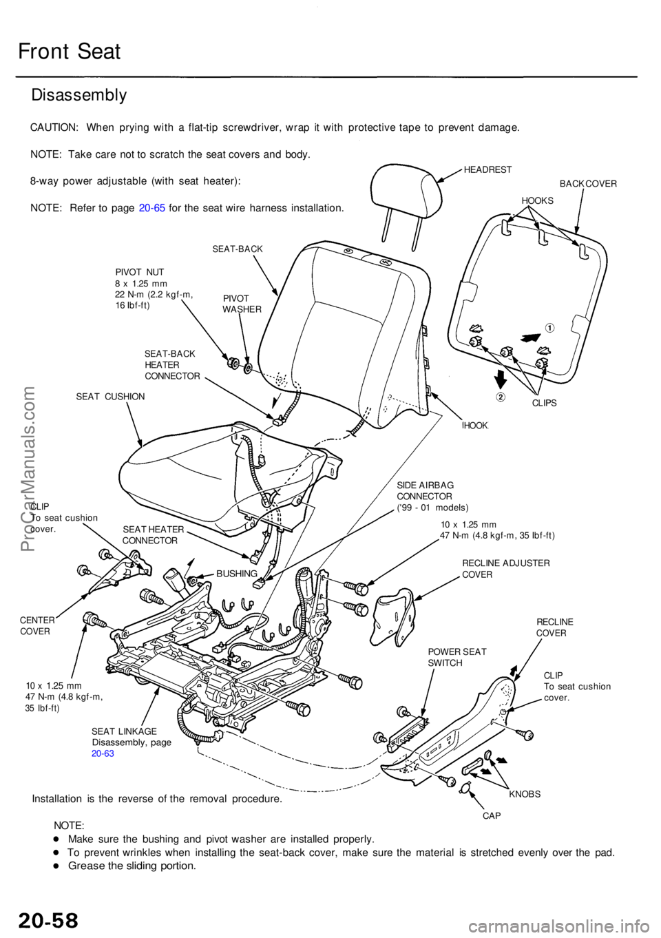
Front Sea t
Disassembl y
CAUTION: Whe n pryin g wit h a flat-ti p screwdriver , wra p i t wit h protectiv e tap e t o preven t damage .
NOTE : Tak e car e no t t o scratc h th e sea t cover s an d body .
HEADRES T8-way powe r adjustabl e (wit h sea t heater) :
NOTE : Refe r t o pag e 20-6 5 fo r th e sea t wir e harnes s installation .BACK COVE R
SEAT-BAC K
PIVOT NU T8 x 1.2 5 mm22 N- m (2. 2 kgf-m ,
1 6 Ibf-ft )
SEA T CUSHIO N
CLIPTo sea t cushio n
cover .
CENTE RCOVER
10 x 1.2 5 mm47 N- m (4. 8 kgf-m ,35 Ibf-ft )
CLIPTo sea t cushio n
cover .
SEA T LINKAG E
Disassembly , pag e20-63
Installatio n i s th e revers e o f th e remova l procedure .KNOBS
CAPNOTE :
Mak e sur e th e bushin g an d pivo t washe r ar e installe d properly .
T o preven t wrinkle s whe n installin g th e seat-bac k cover , mak e sur e th e materia l i s stretche d evenl y ove r th e pad .
Greas e th e slidin g portion .
POWER SEA T
SWITC H
RECLIN ECOVER
RECLIN E ADJUSTE RCOVER
10 x 1.2 5 m m47 N- m (4. 8 kgf-m , 3 5 Ibf-ft )
BUSHIN G
SEAT HEATE R
CONNECTO R SID
E AIRBA G
CONNECTO R
('9 9 - 0 1 models )
HOOK
CLIPS
SEAT-BAC KHEATER
CONNECTO RPIVO
T
WASHE R
HOOKS
ProCarManuals.com
Page 1375 of 1954

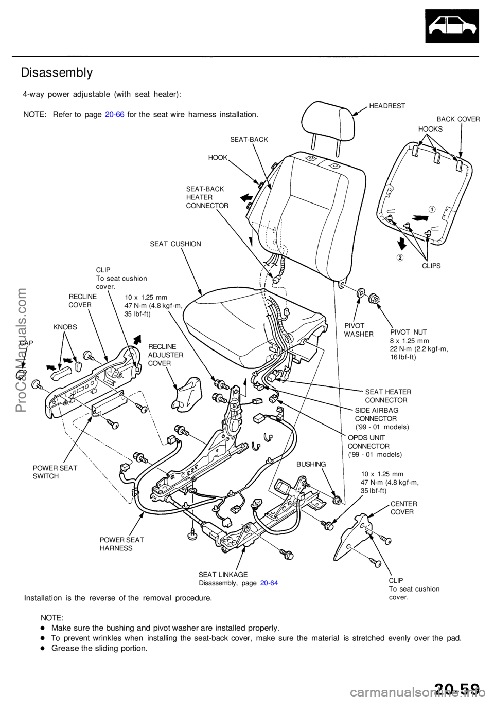
4-way powe r adjustabl e (wit h sea t heater) :
NOTE : Refe r t o pag e 20-6 6 fo r th e sea t wir e harnes s installation .
HEADREST
BACK COVE R
HOOKS
SEAT-BAC K
HOOK
POWE R SEA T
SWITC H
POWER SEA T
HARNES S
SEAT LINKAG E
Disassembly , pag e 20-6 4
Installatio n i s th e revers e o f th e remova l procedure .
CLIPTo sea t cushio n
cover .
NOTE :
Make sur e th e bushin g an d pivo t washe r ar e installe d properly .
To preven t wrinkle s whe n installin g th e seat-bac k cover , mak e sur e th e materia l i s stretche d evenl y ove r th e pad .
Greas e th e slidin g portion .
SEAT-BAC KHEATERCONNECTO R
SEA T CUSHIO N
CLIPS
PIVO T NU T8 x 1.2 5 mm22 N- m (2. 2 kgf-m ,
1 6 Ibf-ft )
SEAT HEATE RCONNECTO R
PIVO
T
WASHE R
SIDE AIRBA G
CONNECTO R
('9 9 - 0 1 models )
OPDS UNI TCONNECTO R
('9 9 - 0 1 models )
BUSHIN G
CLIPTo sea t cushio n
cover .
10 x 1.2 5 mm47 N- m (4. 8 kgf-m ,35 Ibf-ft )
RECLIN ECOVER
KNOBS
CAPRECLIN EADJUSTE R
COVE R
10 x 1.2 5 mm47 N- m (4. 8 kgf-m ,
3 5 Ibf-ft )
CENTE RCOVER
Disassembl y
ProCarManuals.com
Page 1376 of 1954

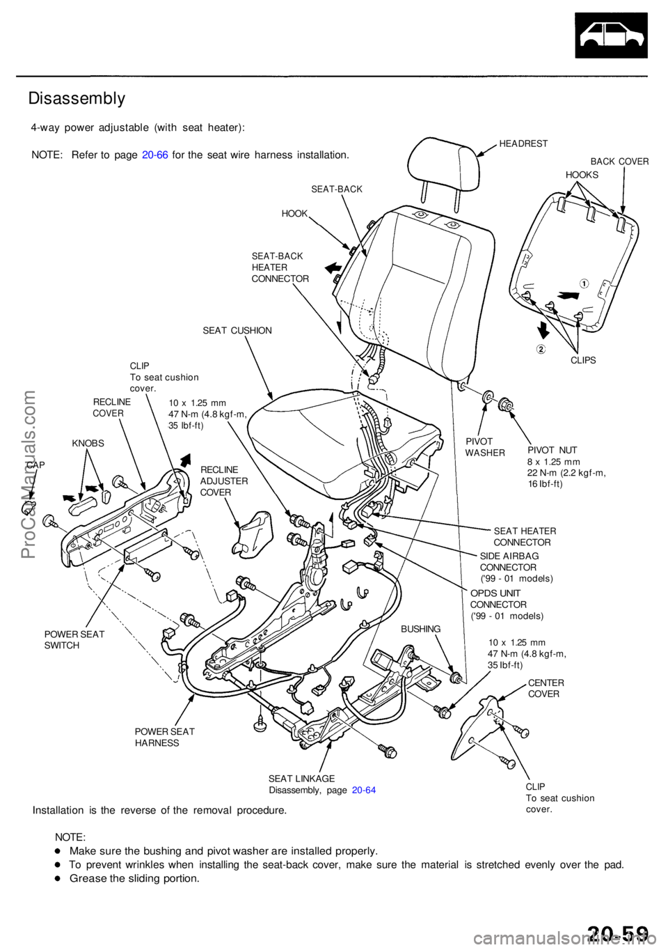
4-way powe r adjustabl e (wit h sea t heater) :
NOTE : Refe r t o pag e 20-6 6 fo r th e sea t wir e harnes s installation .
HEADREST
BACK COVE R
HOOKS
SEAT-BAC K
HOOK
POWE R SEA T
SWITC H
POWER SEA T
HARNES S
SEAT LINKAG E
Disassembly , pag e 20-6 4
Installatio n i s th e revers e o f th e remova l procedure .
CLIPTo sea t cushio n
cover .
NOTE :
Make sur e th e bushin g an d pivo t washe r ar e installe d properly .
To preven t wrinkle s whe n installin g th e seat-bac k cover , mak e sur e th e materia l i s stretche d evenl y ove r th e pad .
Greas e th e slidin g portion .
SEAT-BAC KHEATERCONNECTO R
SEA T CUSHIO N
CLIPS
PIVO T NU T8 x 1.2 5 mm22 N- m (2. 2 kgf-m ,
1 6 Ibf-ft )
SEAT HEATE RCONNECTO R
PIVO
T
WASHE R
SIDE AIRBA G
CONNECTO R
('9 9 - 0 1 models )
OPDS UNI TCONNECTO R
('9 9 - 0 1 models )
BUSHIN G
CLIPTo sea t cushio n
cover .
10 x 1.2 5 mm47 N- m (4. 8 kgf-m ,35 Ibf-ft )
RECLIN ECOVER
KNOBS
CAPRECLIN EADJUSTE R
COVE R
10 x 1.2 5 mm47 N- m (4. 8 kgf-m ,
3 5 Ibf-ft )
CENTE RCOVER
Disassembl y
ProCarManuals.com
Page 1382 of 1954
Page 1383 of 1954
Front Sea t
Seat Wir e Harnes s Installatio n (cont'd )
4-way powe r adjustabl e (wit h sea t heate r an d sid e airbag) :
: Scre w locatio n :
Cli p location s
SEAT-BAC K
SIDE AIRBA G
('9 9 - 0 0 models )
WIRETIES
OPD S UNI T('99 - 0 0 models )
SEAT-BAC KHEATERHARNES S
HOOKS
SLIDE MOTO R
CONNECTO R
To powe rseatswitch .
SEAT-BAC KHEATERCONNECTO R T
o sea t bel t
buckle .
T o sea t
cushio n
heater . SEA
T
CUSHIO NCOVER
WIRETIES
WIR ETIES
WIRETIES
ProCarManuals.com
Page 1484 of 1954

Heater Uni t
Replacemen t
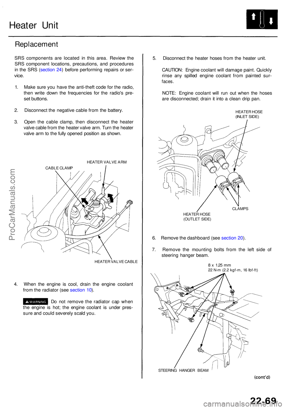
SRS component s ar e locate d i n thi s area . Revie w th e
SR S componen t locations , precautions , an d procedure s
i n th e SR S (sectio n 24 ) befor e performin g repair s o r ser -
vice.
1. Mak e sur e yo u hav e th e anti-thef t cod e fo r th e radio ,
the n writ e dow n th e frequencie s fo r th e radio' s pre -
set buttons .
2. Disconnec t th e negativ e cabl e fro m th e battery .
3 . Ope n th e cabl e clamp , the n disconnec t th e heate r
valv e cabl e fro m th e heate r valv e arm . Tur n th e heate r
valv e ar m to th e full y opene d positio n a s shown .
HEATE R VALV E AR M
CABL E CLAM P
HEATER VALV E CABL E
4. Whe n th e engin e i s cool , drai n th e engin e coolan t
fro m th e radiato r (se e sectio n 10 ).
D o no t remov e th e radiato r ca p whe n
th e engin e i s hot ; th e engin e coolan t i s unde r pres -
sur e an d coul d severel y scal d you . 5
. Disconnec t th e heate r hose s fro m th e heate r unit .
CAUTION : Engin e coolan t wil l damag e paint . Quickl y
rins e an y spille d engin e coolan t fro m painte d sur -
faces .
NOTE : Engin e coolan t wil l ru n ou t whe n th e hose s
ar e disconnected ; drai n it int o a clea n dri p pan .
HEATE R HOS E(INLE T SIDE )
CLAMP S
HEATE R HOS E
(OUTLE T SIDE )
6. Remov e th e dashboar d (se e sectio n 20 ).
7 . Remov e th e mountin g bolt s fro m th e lef t sid e o f
steerin g hange r beam .
8 x 1.2 5 mm22 N- m (2. 2 kgf-m , 1 6 Ibf-ft )
STEERIN G HANGE R BEA M
ProCarManuals.com