Page 671 of 2543
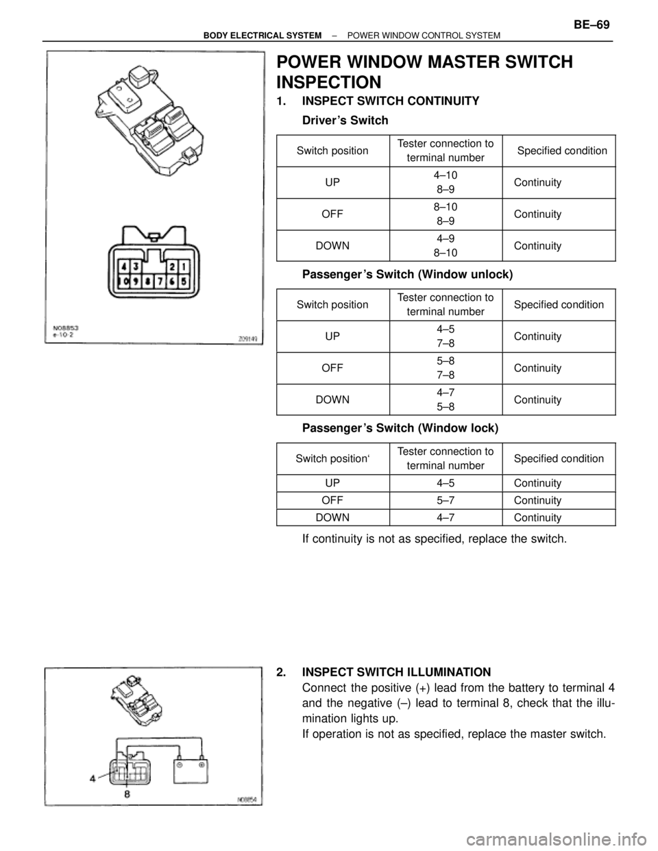
POWER WINDOW MASTER SWITCH
INSPECTION
1. INSPECT SWITCH CONTINUITY
Driver 's Switch
�������� �
������� ��������
Switch position�������� �
������� ��������
Tester connection to
terminal number�������� �
������� ��������
Specified condition
�������� �
�������
UP�������� �
�������
4±10
8±9�������� �
�������
Continuity
�������� �
������� ��������OFF
�������� �
������� ��������8±10
8±9
�������� �
������� ��������Continuity
�������� �
������� ��������DOWN
�������� �
������� ��������4±9
8±10
�������� �
������� ��������Continuity
Passenger 's Switch (Window unlock)
�������� �
������� ��������Switch position
�������� �
������� ��������
Tester connection to
terminal number�������� �
������� ��������Specified condition
�������� �
������� ��������UP�������� �
������� ��������
4±5
7±8�������� �
������� ��������Continuity
�������� �
������� ��������OFF�������� �
������� ��������
5±8
7±8�������� �
������� ��������Continuity
�������� �
������� ��������DOWN�������� �
������� ��������
4±7
5±8�������� �
������� ��������Continuity
Passenger 's Switch (Window lock)
�������� �
������� ��������Switch position`
�������� �
������� ��������Tester connection to
terminal number�������� �
������� ��������Specified condition
�������� ��������UP�������� ��������4±5�������� ��������Continuity�������� ��������OFF�������� ��������5±7�������� ��������Continuity�������� ��������DOWN�������� ��������4±7�������� ��������Continuity
If continuity is not as specified, replace the switch.
2. INSPECT SWITCH ILLUMINATION
Connect the positive (+) lead from the battery to terminal 4
and the negative (±) lead to terminal 8, check that the illu-
mination lights up.
If operation is not as specified, replace the master switch.
± BODY ELECTRICAL SYSTEMPOWER WINDOW CONTROL SYSTEMBE±69
Page 672 of 2543
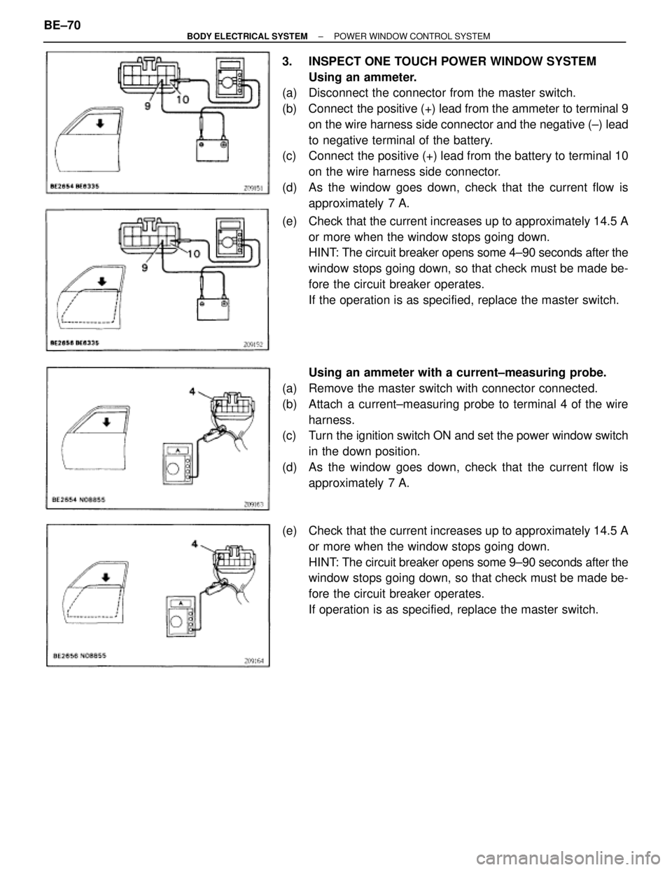
3. INSPECT ONE TOUCH POWER WINDOW SYSTEM
Using an ammeter.
(a) Disconnect the connector from the master switch.
(b) Connect the positive (+) lead from the ammeter to terminal 9
on the wire harness side connector and the negative (±) lead
to negative terminal of the battery.
(c) Connect the positive (+) lead from the battery to terminal 10
on the wire harness side connector.
(d) As the window goes down, check that the current flow is
approximately 7 A.
(e) Check that the current increases up to approximately 14.5 A
or more when the window stops going down.
HINT: The circuit breaker opens some 4±90 seconds after the
window stops going down, so that check must be made be-
fore the circuit breaker operates.
If the operation is as specified, replace the master switch.
Using an ammeter with a current±measuring probe.
(a) Remove the master switch with connector connected.
(b) Attach a current±measuring probe to terminal 4 of the wire
harness.
(c) Turn the ignition switch ON and set the power window switch
in the down position.
(d) As the window goes down, check that the current flow is
approximately 7 A.
(e) Check that the current increases up to approximately 14.5 A
or more when the window stops going down.
HINT: The circuit breaker opens some 9±90 seconds after the
window stops going down, so that check must be made be-
fore the circuit breaker operates.
If operation is as specified, replace the master switch. BE±70
± BODY ELECTRICAL SYSTEMPOWER WINDOW CONTROL SYSTEM
Page 673 of 2543
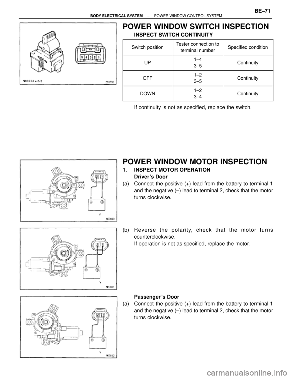
POWER WINDOW SWITCH INSPECTION
INSPECT SWITCH CONTINUITY
�������� �
������� ��������Switch position
�������� �
������� ��������
Tester connection to
terminal number�������� �
������� ��������Specified condition
�������� �
������� ��������UP
�������� �
������� ��������
1±4
3±5�������� �
������� ��������Continuity
�������� �
������� ��������OFF
�������� �
������� ��������1±2
3±5�������� �
������� ��������Continuity
�������� �
������� ��������DOWN
�������� �
������� ��������1±2
3±4�������� �
������� ��������Continuity
If continuity is not as specified, replace the switch.
POWER WINDOW MOTOR INSPECTION
1. INSPECT MOTOR OPERATION
Driver 's Door
(a) Connect the positive (+) lead from the battery to terminal 1
and the negative (±) lead to terminal 2, check that the motor
turns clockwise.
(b) R e v e r s e t h e p o l a r i t y, c h e c k t h a t t h e m o t o r t u r n s
counterclockwise.
If operation is not as specified, replace the motor.
Passenger 's Door
(a) Connect the positive (+) lead from the battery to terminal 1
and the negative (±) lead to terminal 2, check that the motor
turns clockwise.
± BODY ELECTRICAL SYSTEMPOWER WINDOW CONTROL SYSTEMBE±71
Page 674 of 2543
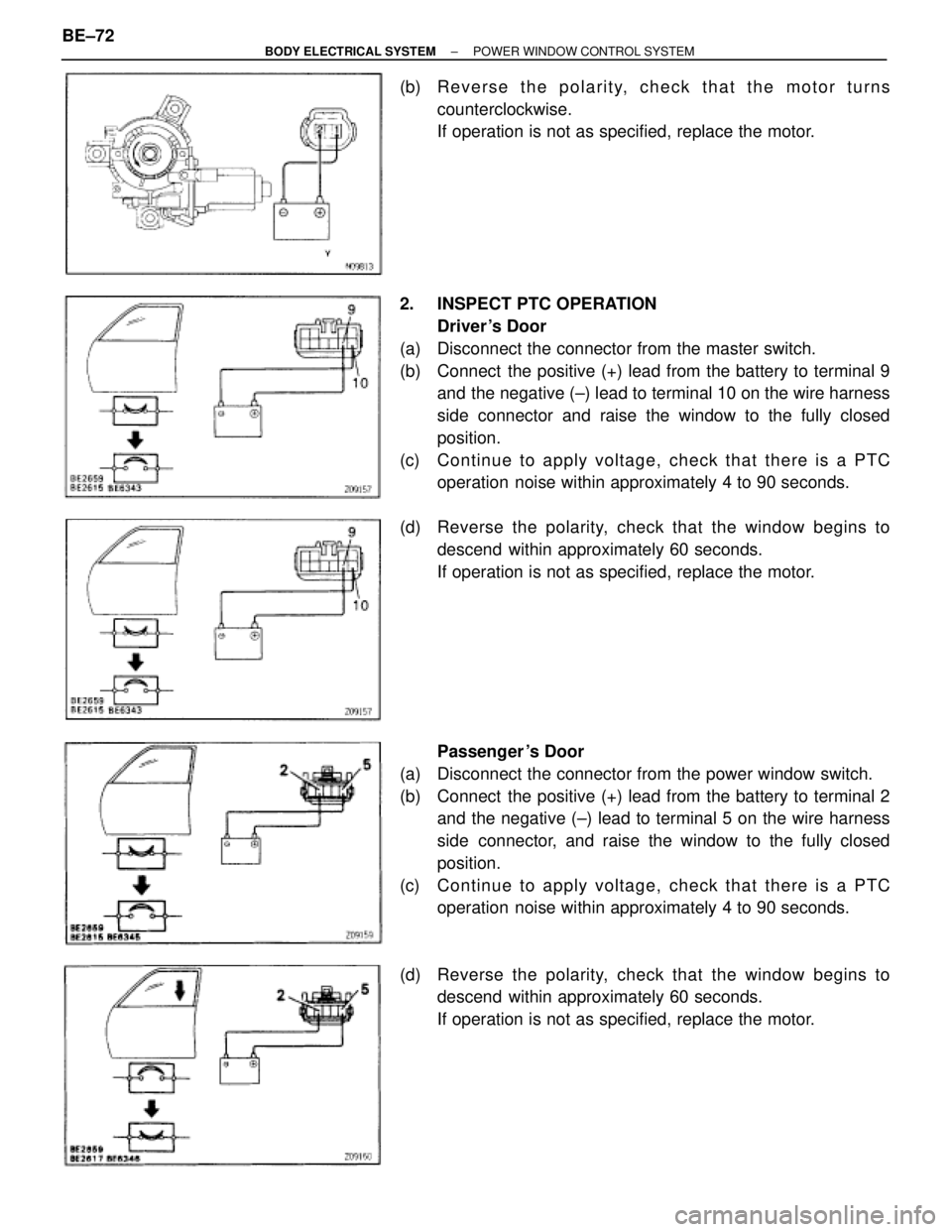
(b) R e v e r s e t h e p o l a r i t y, c h e c k t h a t t h e m o t o r t u r n s
counterclockwise.
If operation is not as specified, replace the motor.
2. INSPECT PTC OPERATION
Driver 's Door
(a) Disconnect the connector from the master switch.
(b) Connect the positive (+) lead from the battery to terminal 9
and the negative (±) lead to terminal 10 on the wire harness
side connector and raise the window to the fully closed
position.
(c) Continue to apply voltage, check that there is a PTC
operation noise within approximately 4 to 90 seconds.
(d) Reverse the polarity, check that the window begins to
descend within approximately 60 seconds.
If operation is not as specified, replace the motor.
Passenger 's Door
(a) Disconnect the connector from the power window switch.
(b) Connect the positive (+) lead from the battery to terminal 2
and the negative (±) lead to terminal 5 on the wire harness
side connector, and raise the window to the fully closed
position.
(c) Continue to apply voltage, check that there is a PTC
operation noise within approximately 4 to 90 seconds.
(d) Reverse the polarity, check that the window begins to
descend within approximately 60 seconds.
If operation is not as specified, replace the motor. BE±72
± BODY ELECTRICAL SYSTEMPOWER WINDOW CONTROL SYSTEM
Page 678 of 2543
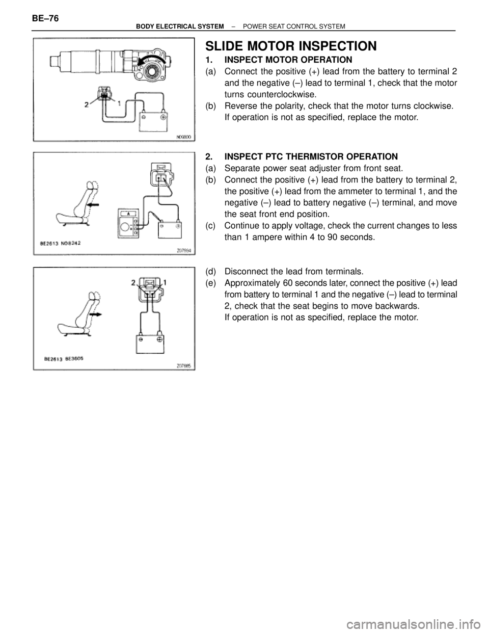
SLIDE MOTOR INSPECTION
1. INSPECT MOTOR OPERATION
(a) Connect the positive (+) lead from the battery to terminal 2
and the negative (±) lead to terminal 1, check that the motor
turns counterclockwise.
(b) Reverse the polarity, check that the motor turns clockwise.
If operation is not as specified, replace the motor.
2. INSPECT PTC THERMISTOR OPERATION
(a) Separate power seat adjuster from front seat.
(b) Connect the positive (+) lead from the battery to terminal 2,
the positive (+) lead from the ammeter to terminal 1, and the
negative (±) lead to battery negative (±) terminal, and move
the seat front end position.
(c) Continue to apply voltage, check the current changes to less
than 1 ampere within 4 to 90 seconds.
(d) Disconnect the lead from terminals.
(e) Approximately 60 seconds later, connect the positive (+) lead
from battery to terminal 1 and the negative (±) lead to terminal
2, check that the seat begins to move backwards.
If operation is not as specified, replace the motor. BE±76
± BODY ELECTRICAL SYSTEMPOWER SEAT CONTROL SYSTEM
Page 679 of 2543
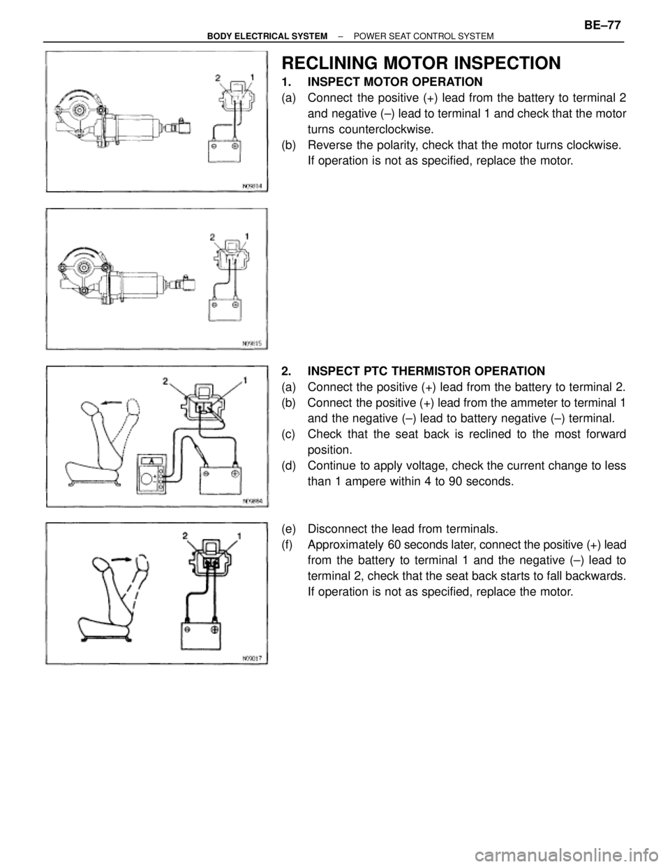
RECLINING MOTOR INSPECTION
1. INSPECT MOTOR OPERATION
(a) Connect the positive (+) lead from the battery to terminal 2
and negative (±) lead to terminal 1 and check that the motor
turns counterclockwise.
(b) Reverse the polarity, check that the motor turns clockwise.
If operation is not as specified, replace the motor.
2. INSPECT PTC THERMISTOR OPERATION
(a) Connect the positive (+) lead from the battery to terminal 2.
(b) Connect the positive (+) lead from the ammeter to terminal 1
and the negative (±) lead to battery negative (±) terminal.
(c) Check that the seat back is reclined to the most forward
position.
(d) Continue to apply voltage, check the current change to less
than 1 ampere within 4 to 90 seconds.
(e) Disconnect the lead from terminals.
(f) Approximately 60 seconds later, connect the positive (+) lead
from the battery to terminal 1 and the negative (±) lead to
terminal 2, check that the seat back starts to fall backwards.
If operation is not as specified, replace the motor.
± BODY ELECTRICAL SYSTEMPOWER SEAT CONTROL SYSTEMBE±77
Page 682 of 2543
MIRROR MOTOR INSPECTION
INSPECT MOTOR OPERATION
(a) Connect the positive (+) lead from the battery to terminal 3
and negative (±) lead to terminal 4, check that the mirror turns
upward.
(b) Reverse the polarity, check that the mirror turns to downward.
(c) Connect the positive (+) lead from the battery to terminal 5
and negative (±) lead to terminal 4, check that the mirror turns
to left side.
(d) Reverse the polarity, check that the mirror turns to right side.
If operation is not as specified, replace the mirror. BE±80
± BODY ELECTRICAL SYSTEMPOWER MIRROR CONTROL SYSTEM
Page 686 of 2543

ANTI±THEFT SYSTEM
HINT: The words ºANTI±THEFT SYSTEMº are displayed on
the cassette tape slot cover.
For operation instructions for the anti±theft system, please
consult the audio system section in the Owner's Manual
(hereafter called O/M).
1. SETTING SYSTEM
The system is in operation once the customer has pushed the
required buttons and entered the customer±selected 3±digit
ID number.
(Refer to the O/M section, ºSetting the anti±theft systemº)
HINT:
w When the audio system is shipped the ID number has
not been input, so the anti±theft system is not in
operation.
w If the ID number has not been input, the audio system
remains the same as a normal audio system.
2. ANTI±THEFT SYSTEM OPERATION
If the normal electrical power source (connector or battery
terminal) is cut off, the audio system becomes inoperable,
even if the power supply resumes.
3. CANCELING SYSTEM
The ID number chosen by the customer is input to cancel the
anti±theft system.
(Refer to the O/M section, ºIf the system is activatedº)
HINT: To change or cancel the ID number, please refer to the
O/M section ºCancelling the systemº. BE±84
± BODY ELECTRICAL SYSTEMAUDIO SYSTEM