Page 939 of 2543

Replace ABS solenoid relay.
Repair or replace harness or connector.
Check ABS solenoid relay.
Remove solenoid relay from R/B No. 5.
Check continuity between each terminal of ABS
solenoid relay shown below.
1. Apply battery voltage between terminals 4
and 6.
2. Check continuity between each terminal of
ABS solenoid relay shown below.
Check for open and short in harness and connector between ABS solenoid
relay and ABS & TRAC ECU (See page IN±30).
Terminals 1 and 3
Continuity
Continuity
(Reference value 80 �)
Open
Terminals 2 and 3
Terminals 4 and 6
Terminals 2 and 3
Terminals 1 and 3Continuity
Open
������������������������������������ �
����������������������������������� �
����������������������������������� ������������������������������������
If the same code is still output after the diagnostic trouble code is deleted, check the contact condi-
tion of each connection.
If the connections are normal, the ECU may be defective.
BR±70± BRAKE SYSTEMANTI±LOCK BRAKE SYSTEM (ABS)
Page 940 of 2543

EFEF
DTC 13 14 ABS Motor Relay Circuit
CIRCUIT DESCRIPTION
The ABS motor relay supplies power to the ABS pump motor. While the ABS is activated, the ECU switches
the motor relay ON and operates the ABS pump motor.
������� �������DTC No.����������������� �����������������Diagnostic Trouble Code Detecting Condition�������������� ��������������Trouble area
������� �
������ �
������ �
������ �
������ �
������ �������
13
����������������� �
���������������� �
���������������� �
���������������� �
���������������� �
���������������� �����������������
Conditions (1) and (2) continue for 0.2 sec.
or more:
(1) ABS motor relay terminal (MR)
voltage: Battery positive voltage
(2) Motor relay monitor terminal (MT)
voltage: O V�������������� �
������������� �
������������� �
������������� �
������������� �
������������� ��������������
� ABS motor relay
� Open or short in ABS motor relay circuit
� ECU
������� �
������ �
������ �
������ �
������ �������
14
����������������� �
���������������� �
���������������� �
���������������� �
���������������� �����������������
Conditions (1) and (2) continue for 4 sec. or
more:
(1) ABS motor relay terminal (MR)
voltage: O V
(2) Motor relay monitor terminal (MT)
voltage: Battery positive voltage�������������� �
������������� �
������������� �
������������� �
������������� ��������������
� ABS motor relay
� B+ short in ABS motor relay circuit
� ECU
Fail safe function: If trouble occurs in the motor relay circuit, the ECU cuts off the current to the solenoid relay
and prohibits ABS control.
± BRAKE SYSTEMANTI±LOCK BRAKE SYSTEM (ABS)BR±71
Page 943 of 2543
Check continuity between each terminal of ABS
motor relay shown below.
Check ABS motor relay.
(1) Apply battery voltage between terminals
(A8) 3 and (A8) 4.
(2) Check continuity between each terminal of
ABS motor relay shown below.
Replace ABS control relay.
Check for open and short in harness and connector between ABS motor
relay and ABS ECU (See page IN±30).
Repair or replace harness or connector.
Terminals
Terminals
3 and
1 and
4
2
Continuity (Reference
value 62 � )
Open
Terminals1 and2Continuity
������������������������������������ �
����������������������������������� ������������������������������������
If the same code is still output after the diagnostic trouble code is deleted, check the contact
condition of each connection.
If the connections are normal, the ECU may be defective.
BR±74± BRAKE SYSTEMANTI±LOCK BRAKE SYSTEM (ABS)
Page 945 of 2543
Remove motor relay from R/B No. 5.
Check continuity between each pair of terminals of
motor relay shown below.
Check ABS motor relay.
1. Apply battery voltage between terminals
3 and 4.
2. Check continuity between each terminal
shown below.
Terminals 1 and 2Continuity
Terminals 1 and 2Open
Continuity
(Reference value 62 �)Terminals 3 and 4
Check for open and short in harness and connector between ABS motor
relay and ABS TRAC ECU (See page IN±30).
������������������������������������ �
����������������������������������� ������������������������������������
If the same code is still output after the diagnostic trouble code is deleted, check the contact
condition of each connection.
If the connections are normal, the ECU may be defective.
BR±76± BRAKE SYSTEMANTI±LOCK BRAKE SYSTEM (ABS)
Page 946 of 2543

DTC 15 16 TRAC Solenoid Relay Circuit
CIRCUIT DESCRIPTION
This relay circuit supplies power to each traction actuator solenoid.
When the ignition switch is turned ON, the relay goes on.
������ ������DTC No.��������������� ���������������Diagnostic Trouble Code Detecting Condition����������������� �����������������Trouble area������ �
����� �
����� �
����� �
����� �
����� �
����� ������
15
��������������� �
�������������� �
�������������� �
�������������� �
�������������� �
�������������� �
�������������� ���������������
Conditions (1) through (3) continue for 0.2
sec. or more:
(1) TRAC solenoid relay terminal (TSR)
voltage: Battery positive voltage
(2) All TRAC actuator solenoids: OFF
(3) All TRAC actuator solenoid monitor
voltages (in ECU): 0 V����������������� �
���������������� �
���������������� �
���������������� �
���������������� �
���������������� �
���������������� �����������������
� TRAC solenoid relay
� Open or short in TRAC solenoid relay circuit
� ECU
������ �
����� �
����� �
����� �
����� �
����� ������
16
��������������� �
�������������� �
�������������� �
�������������� �
�������������� �
�������������� ���������������
Conditions (1) through (3) continue for 0.2
sec. or more:
(1) TRAC solenoid relay terminal (TSR)
voltage: 0 V
(2) All TRAC actuator solenoids: OFF
(3) TRAC actuator solenoid monitor voltage
(in ECU): Battery positive voltage����������������� �
���������������� �
���������������� �
���������������� �
���������������� �
���������������� �����������������
� TRAC solenoid relay
� B+ short in TRAC solenoid relay circuit
� ECU
Fail safe function: If trouble occurs in this relay circuit, the ECU cuts off current to the ABS and TRAC solenoid
relays and prohibits ABS and TRAC control.
± BRAKE SYSTEMANTI±LOCK BRAKE SYSTEM (ABS)BR±77
Page 948 of 2543
Check TRAC solenoid relay.
Remove TRAC solenoid relay from R/B No. 5.
Check continuity between each terminal of TRAC
solenoid relay shown below.
Replace TRAC solenoid relay.
Terminals 1 and 3Open
Continuity
(Reference value 80 �)Terminals 4 and 6
Terminals 2 and 3Continuity
1. Apply battery voltage between terminals
4 and 6.
2. Check continuity between terminal shown
below.
Repair or replace harness or connector.
Terminals 1 and 3
OpenTerminals 2 and 3
Continuity
Check for open and short in harness and connector between TRAC
solenoid relay and ABS & TRAC ECU (See page
IN±30).
������������������������������������ �
����������������������������������� ������������������������������������
If the same code is still output after the diagnostic trouble code is deleted, check the contact
condition of each connection.
If the connections are normal, the ECU may be defective.
± BRAKE SYSTEMANTI±LOCK BRAKE SYSTEM (ABS)BR±79
Page 949 of 2543

DTC 17 18 TRAC Motor Relay Circuit
CIRCUIT DESCRIPTION
This relay circuit supplies power to the TRAC pump motor. While the TRAC is activated, the ECU switches the
motor relay ON and operates the TRAC pump motor.
������ ������DTC No.����������������� �����������������Diagnostic Trouble Code Detecting Condition��������������� ���������������Trouble area
������ �
����� �
����� �
����� �
����� ������
17
����������������� �
���������������� �
���������������� �
���������������� �
���������������� �����������������
Conditions (1) and (2) continue for 0.2 sec.
or more:
(1) TRAC motor relay terminal (TMR)
voltage: Battery positive voltage
(2) Voltage of ABS & TRAC ECU terminal
MTT: 0 V��������������� �
�������������� �
�������������� �
�������������� �
�������������� ���������������
� TRAC motor relay
� Open or short in TRAC motor relay circuit
� ECU
������ �
����� �
����� �
����� �
����� �
����� ������
18
����������������� �
���������������� �
���������������� �
���������������� �
���������������� �
���������������� �����������������
Conditions (1) and (2) continue for 2 sec. or
more:
(1) TRAC motor relay terminal (TMR)
voltage: 0 V
(2) Voltage of ABS & TRAC ECU terminal
MTT: Battery positive voltage��������������� �
�������������� �
�������������� �
�������������� �
�������������� �
�������������� ���������������
� TRAC motor relay
� B+ short in TRAC motor relay circuit
� ECU
Fail safe function: If trouble occurs in this relay circuit, the ECU cuts off current to the TRAC solenoid relay
and prohibits TRAC control.
BR±80± BRAKE SYSTEMANTI±LOCK BRAKE SYSTEM (ABS)
Page 951 of 2543
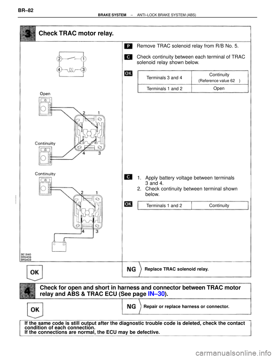
Check TRAC motor relay.
Remove TRAC solenoid relay from R/B No. 5.
Check continuity between each terminal of TRAC
solenoid relay shown below.
Terminals 1 and 2
Open
Continuity
(Reference value 62��)Terminals 3 and 4
Terminals 1 and 2
Continuity
1. Apply battery voltage between terminals
3 and 4.
2. Check continuity between terminal shown
below.
Replace TRAC solenoid relay.
Repair or replace harness or connector.
Check for open and short in harness and connector between TRAC motor
relay and ABS & TRAC ECU (See page
IN±30).
If the same code is still output after the diagnostic trouble code is deleted, check the contact
condition of each connection.
If the connections are normal, the ECU may be defective. BR±82
± BRAKE SYSTEMANTI±LOCK BRAKE SYSTEM (ABS)
 Apply battery voltage between terminals
(A8) 3 and (A8) 4.
(2) Check continuity between each terminal")