Page 714 of 2543
 terminal cable
connected to the battery.
(a) Turn the ignition switch to ºLOCKº position.")
ANTENNA ROD REMOVAL AND
INSTALLATION
1. REMOVE ANTENNA ROD
HINT: Do this operation with the negative (±) terminal cable
connected to the battery.
(a) Turn the ignition switch to ºLOCKº position.
(b) Remove the antenna nut.
(c) P r e s s t h e º A M º b u t t o n o n t h e r a d i o r e c e i v e r, a n d
simultaneously turn the ignition switch to ºACCº position.
HINT:
wThe rod will extend fully and be released from the motor
antenna.
wAfter removing the antenna rod, leave the ignition switch
at ºACCº.
NOTICE: To prevent body damage when the antenna rod
is released, hold the rod while it comes out.
2. INSTALL ANTENNA ROD
(a) Insert the cable of the rod until it reaches the bottom.
HINT:
wWhen inserting the cable, the teeth on the cable must
face toward the rear of the vehicle.
wInsert the cable approx. 400 mm.
(b) Wind the cable to retract the rod by turning the ignition switch
to ºLOCKº position.
HINT:
wIf the ignition switch is already in ºLOCKº position, do
step 1 (c) first, then turn the ignition switch to ºACCº
position.
wIn case the cable is not wound, twist it as shown in the
illustration.
wEven if the rod has not retracted fully, install the antenna
nut and inspect the antenna rod operation. It will finally
retract fully.
(c) Inspect the antenna rod operation by pushing the radio wave
band select buttons. BE±112
± BODY ELECTRICAL SYSTEMAUDIO SYSTEM
Page 715 of 2543

MOTOR ANTENNA CONTROL RELAY
INSPECTION
INSPECT RELAY CIRCUIT
Disconnect the connector from the relay and inspect connec-
tor on wire harness side, as shown in the chart.
����������� �
���������� �����������
Tester connection to
terminal number��������������� �
�������������� ���������������Condition������������ �
����������� ������������Specified condition
����������� �����������6±Ground��������������� ���������������Constant������������ ������������Continuity
����������� �����������2±3��������������� ���������������Constant������������ ������������Continuity����������� �
���������� �����������1±Ground
��������������� �
�������������� ���������������Constant
������������ �
����������� ������������Battery positive voltage
����������� �����������4±Ground��������������� ���������������Ignition switch position ON������������ ������������Battery positive voltage
����������� �����������5±Ground��������������� ���������������Ignition switch position ACC or ON������������ ������������Battery positive voltage
����������� �
���������� �����������7±Ground
��������������� �
�������������� ���������������Ignition switch position ACC or ON
and radio switch ON������������ �
����������� ������������Battery positive voltage
����������� �����������8±Ground��������������� ���������������Ignition switch position ACC or ON������������ ������������Battery positive voltage
If circuit is not as specified, replace the relay.
± BODY ELECTRICAL SYSTEMAUDIO SYSTEMBE±113
Page 716 of 2543
MOTOR ANTENNA INSPECTION
INSPECT MOTOR ANTENNA
(a) Install antenna nut.
(b) Connect the positive (+) lead from the battery to terminal 1
and the negative (±) lead to terminal 2.
(c) Check that the motor turns (moves upward).
NOTICE: These tests must be done quickly (within 3±5
seconds) to prevent the coil from burning out.
(d) Then, reverse the polarity, check that the motor turns the
opposite way (moves downward).
NOTICE: These tests must be done quickly (within 3±5
seconds) to prevent the coil from burning out.
HINT: When the motor is normal, lower the antenna to its low-
est position.
If operation is not as specified, replace the antenna motor as-
sembly.
GLASS PRINTED ANTENNA
INSPECTION
1. INSPECT GLASS PRINTED ANTENNA
(Use same procedure as for ºINSPECT DEFOGGER
WIRESº.)
2. REPAIR GLASS PRINTED ANTENNA
(Use same procedure as for ºREPAIR DEFOGGER
WIRESº.) BE±114
± BODY ELECTRICAL SYSTEMAUDIO SYSTEM
Page 717 of 2543
 Check that the battery positive voltage is 10 Ð 16 V.
If voltage is not as specified, replace the battery.
(b) Check that the DOME fuse is not blown.
If the fuse is blown, replace the fuse and c")
(a) Check that the battery positive voltage is 10 Ð 16 V.
If voltage is not as specified, replace the battery.
(b) Check that the DOME fuse is not blown.
If the fuse is blown, replace the fuse and check for
short.
(c) Troubleshoot the clock as follows.
HINT: Inspect the connector on the wire harness side.
Is there battery positive voltage between
terminal +B and body ground?Open or short circuit in wire harness be-
tween terminal +B and DOME fuse.
Is there continuity between terminal
GND and body ground?Open circuit in wire harness between ter-
minal GND and body ground.
Replace clock assembly.
CLOCK
TROUBLESHOOTING
HINT: Troubleshoot the clock according to the table below.
��������������� ���������������Clock will not operate�������� �������� 1��������������� �
�������������� ���������������Clock loses or gains time
�������� �
������� ��������2
��� �
�� ���1
���������������������������������� �
��������������������������������� ����������������������������������CLOCK WILL NOT OPERATE
± BODY ELECTRICAL SYSTEMCLOCKBE±115
Page 718 of 2543
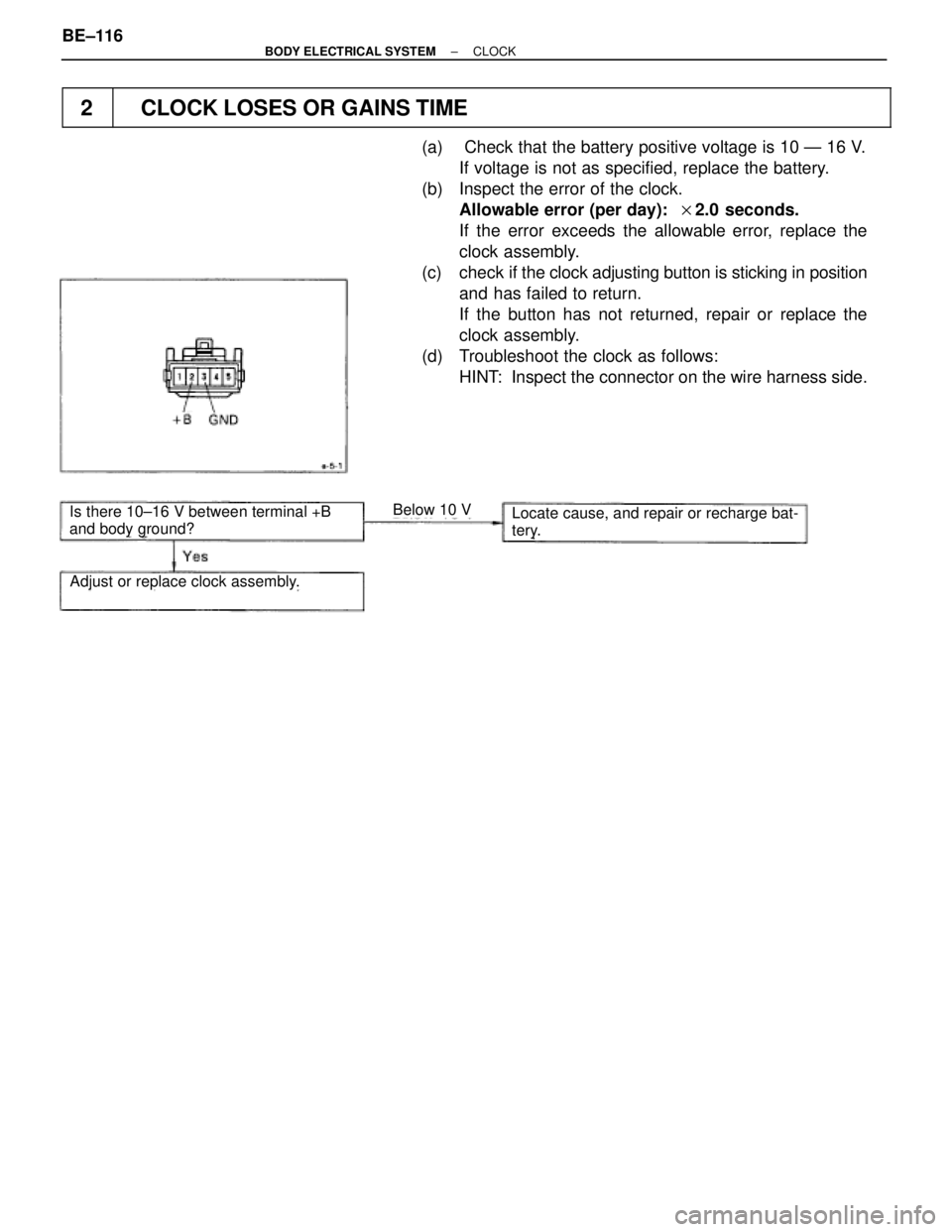
Is there 10±16 V between terminal +B
and body ground?Locate cause, and repair or recharge bat-
tery.
Adjust or replace clock assembly.
Below 10 V
��� �
�� ���2
���������������������������������� �
��������������������������������� ����������������������������������CLOCK LOSES OR GAINS TIME
(a) Check that the battery positive voltage is 10 Ð 16 V.
If voltage is not as specified, replace the battery.
(b) Inspect the error of the clock.
Allowable error (per day): �2.0 seconds.
If the error exceeds the allowable error, replace the
clock assembly.
(c) check if the clock adjusting button is sticking in position
and has failed to return.
If the button has not returned, repair or replace the
clock assembly.
(d) Troubleshoot the clock as follows:
HINT: Inspect the connector on the wire harness side. BE±116
± BODY ELECTRICAL SYSTEMCLOCK
Page 742 of 2543
Ignition Switch Circuit
CIRCUIT DESCRIPTION
When the ignition switch is turned to the ACC position, battery positive voltage is applied to the terminal ACC
of the ECU. Also, if the ignition switch is turned to the ON position, battery voltage is applied to the terminals
ACC and IG of the ECU. When the battery positive voltage is applied to the terminal ACC of the ECU while the
theft deterrent system is activated, the warning stops. Furthermore, power supplied from the terminals ACC and
IG of the ECU is used as power for the door courtesy switch, and position switch, etc.
BE±140± BODY ELECTRICAL SYSTEMTHEFT DETERRENT AND DOOR LOCK CONTROL SYSTEM
Page 743 of 2543
(See page IN±30).
Check for short in all the harness and
components connected to the CIG and ECU±IG
fuses (See attached wiring diagram).
(1) Remove instrument panel.
(See BO section)
(2) Disconnect the ECU connector.
(3) Turn ignition switch ON.
Check and replace theft deterrent and door lock
ECU.
Measure voltage between terminal IG and ACC of
theft deterrent ECU connector and body ground.
Voltage: 10 ± 14 V
Check and repair harness and connector between theft deterrent and door lock ECU and battery
(See page IN±30).
Check voltage between terminals IG and ACC of theft deterrent and door
lock ECU and body ground.
Continuity
Remove CIG and ECU±IG fuses from J/B NO. 1.
Check continuity of CIG and ECU±IG fuses.
Check CIG and ECU±IG fuses.
INSPECTION PROCEDURE
± BODY ELECTRICAL SYSTEMBE±141
THEFT DETERRENT AND DOOR LOCK CONTROL SYSTEM
Page 745 of 2543
.
(1) Remove deck trim rear cover.
(2) Turn ignition switch ON.
Repair or replace luggage compartment door
key lock and unlock switch.
Measure voltage between terminal 1 of luggage
co")
(See page IN±30).
(1) Remove deck trim rear cover.
(2) Turn ignition switch ON.
Repair or replace luggage compartment door
key lock and unlock switch.
Measure voltage between terminal 1 of luggage
compartment door key lock and unlock switch
connector and body ground, when the key si
turned to the unlock side and not turned.
Check and replace theft deterrent and door lock
ECU. *1.
Check harness and connector between theft deterrent and door lock ECU and
key unlock switch, key unlock switch and body ground (See page
IN±30).
Check voltage between terminal 1 of luggage compartment door key lock
and unlock switch connector and body ground.
Key operation
Turned to the unlock side.
Not turned
Voltage
0 V
Battery positive voltage
Check luggage compartment door key lock and unlock switch.
Key operation
Turned to the unlock side.
Not turned
Disconnect luggage compartment door key lock and
unlock switch connector.
Check continuity between terminals 1 and 2, when
the key si turned to the unlock side and not turned.
Continuity
12
Repair or replace harness or connector.
Check and replace theft deterrent
and door lock ECU.
INSPECTION PROCEDURE
*1: When there is a malfunction that the theft deterrent
system cannot be set, proceed to the next
numbered circuit inspection shown on the
matrix chart (See page Be±123).
± BODY ELECTRICAL SYSTEMBE±143THEFT DETERRENT AND DOOR LOCK CONTROL SYSTEM
 Install antenna nut.
(b) Connect the positive (+) lead from the battery to terminal 1
and the negative (±) lead to terminal 2.
(c) Check that th")

.
Check for short in all the harness and
components connected to the CIG and ECU±IG
fuses (See attached wiring diagram).
(1) Remove instrument panel.
(See BO section)
(2) Disconnect")