Page 1404 of 2543
(c) Remove the 4 bolts holding the lever boot to the transmission
cover.
(d) Remove the shift & select lever boots.
(e) Remove the 4 bolts holding the shift lever to the shift lever
retainer.
22. M/T:
DISCONNECT CLUTCH RELEASE CYLINDER AND
GROUND STRAP FROM TRANSMISSION
(a) Remove the 2 bolts, and disconnect clutch release cylinder.
(b) Remove the bolt, and disconnect the clutch line tube.
(c) Remove the bolt, and disconnect ground strap.
23. DISCONNECT SUB HEATED OXYGEN SENSOR FROM
FRONT EXHAUST PIPE
Remove the 2 nuts and sensor cover, and disconnect oxygen
sensor and gasket.
24. REMOVE EXHAUST PIPE ASSEMBLY
(a) Remove the 2 bolts and nuts holding the front exhaust pipe
to the No.2 front exhaust pipe.
(b) Remove the 2 bolts and pipe support bracket.
(c) Remove the gasket, and disconnect the front exhaust pipe. EG±90
± ENGINEENGINE MECHANICAL
Page 1441 of 2543
5. INSTALL EXHAUST PIPE HEAT INSULATOR
6. INSTALL NO.2 FRONT EXHAUST PIPE
(a) Install 2 new gaskets and the No.2 front exhaust pipe to the
exhaust manifold with 4 new nuts.
Torque: 62 NVm (630 kgfVcm, 46 ftVlbf)
(b) Install the pipe support bracket with the 2 bolts.
Torque: 43 NVm (440 kgfVcm, 32 ftVlbf)
(c) Install a new gasket and the No.2 front exhaust pipe to the
front exhaust pipe with the 2 bolts and 2 new nuts.
Torque: 58 NVm (590 kgfVcm, 43 ftVlbf)
7. M/T:
INSTALL CLUTCH RELEASE CYLINDER AND GROUND
STRAP
(a) Install the clutch release cylinder with the 2 bolts.
Torque: 13 NVm (130 kgfVcm, 9 ftVlbf)
(b) Install the ground strap with the bolt.
Torque: 37 NVm (380 kgfVcm, 27 ftVlbf)
8. M/T:
INSTALL UPPER CONSOLE PANEL, SHIFT LEVER
BOOTS AND HOLDING BOLTS
9. CONNECT ENGINE WIRE TO CABIN
(a) Push in the engine wire through the cowl panel.
NOTICE: Be careful not to damage the engine wire.
(b) Connect the connector to the connector cassette.
(c) Connect the connector to the instrament panel wire
connector.
(d) Connect the 2 connectors to the ECM.
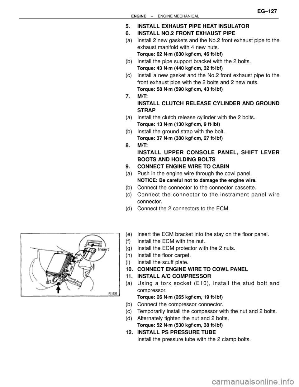
(e) Insert the ECM bracket into the stay on the floor panel.
(f) Install the ECM with the nut.
(g) Install the ECM protector with the 2 nuts.
(h) Install the floor carpet.
(i) Install the scuff plate.
10. CONNECT ENGINE WIRE TO COWL PANEL
11. INSTALL A/C COMPRESSOR
(a) U s i n g a t o r x s o c k e t ( E 1 0 ) , i n s t a l l t h e s t u d b o l t a n d
compressor.
Torque: 26 NVm (265 kgfVcm, 19 ftVlbf)
(b) Connect the compressor connector.
(c) Temporarily install the compessor with the nut and 2 bolts.
(d) Alternately tighten the nut and 2 bolts.
Torque: 52 NVm (530 kgfVcm, 38 ftVlbf)
12. INSTALL PS PRESSURE TUBE
Install the pressure tube with the 2 clamp bolts.
± ENGINEENGINE MECHANICALEG±127
Page 1444 of 2543
5. INSTALL REAR CENTER FLOOR CROSSMEMBER
BRACE
Torque: 28 NVm (290 kgfVcm, 21 ftVlbf)
6. INSTALL EXHAUST PIPE HEAT INSULATOR
7. INSTALL NO.2 FRONT EXHAUST PIPE
Install a new gasket and the front exhaust pipe with 3 new
nuts.
Torque: 62 NVm (630 kgfVcm, 46 ftVlbf)
8. INSTALL EXHAUST PIPE ASSEMBLY
(a) Install the hook of the tailpipe to the 2 rings on the tailpipe
bracket.
(b) Install the hook of the exhaust pipe to the 2 rings on the
exhaust pipe brackets.
(c) Install the pipe support bracket with the 2 bolts.
Torque: 43 NVm (440 kgfVcm, 32 ftVlbf)
(d) Install a new gasket and the No.2 front exhaust pipe to the
front exhaust pipe with the 2 bolts and 2 new nuts.
Torque: 58 NVm (590 kgfVcm, 43 ftVlbf)
9. INSTALL SUB HEATED OXYGEN SENSOR
Install a new gasket, the oxygen sensor and sensor cover
with the 2 nuts.
Torque: 18 NVm (180 kgfVcm, 13 ftVlbf)
10. M/T:
INSTALL CLUTCH RELEASE CYLINDER AND GROUND
STRAP
(a) Install the clutch release cylinder with the 2 bolts.
Torque: 13 NVm (130 kgfVcm, 9 ftVlbf)
(b) Connect the clutch line tube with the bolt.
Torque: 37 NVm (380 kgfVcm, 27 ftVlbf)
(c) Install the ground strap with the bolt.
Torque: 37 NVm (380 kgfVcm, 27 ftVlbf)
11. CONNECT ENGINE WIRE TO CABIN
(a) Push in the engine wire through the cowl panel.
NOTICE: Be careful not to damage the engine wire.
(b) Connect the 2 connectors to the connector cassette.
(c) Connect the connector to the instrument panel wire
connector.
(d) Connect the 2 connectors to the ECM.
(e) Connect the connector to the TRAC ECU.
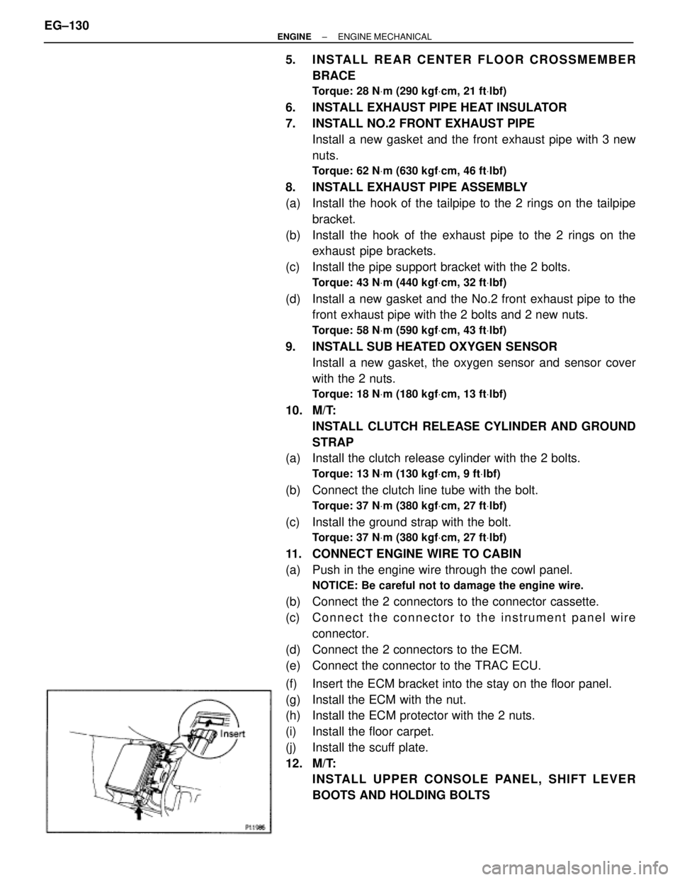
(f) Insert the ECM bracket into the stay on the floor panel.
(g) Install the ECM with the nut.
(h) Install the ECM protector with the 2 nuts.
(i) Install the floor carpet.
(j) Install the scuff plate.
12. M/T:
INSTALL UPPER CONSOLE PANEL, SHIFT LEVER
BOOTS AND HOLDING BOLTS EG±130
± ENGINEENGINE MECHANICAL
Page 1464 of 2543
CENTER SUPPORT BEARING
REPLACEMENT
2JZ±GTE:
1. SEPARATE INTERMEDIATE SHAFT AND PROPELLER
SHAFT
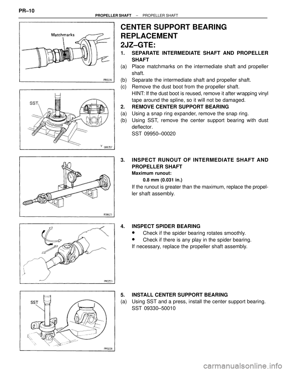
(a) Place matchmarks on the intermediate shaft and propeller
shaft.
(b) Separate the intermediate shaft and propeller shaft.
(c) Remove the dust boot from the propeller shaft.
HINT: If the dust boot is reused, remove it after wrapping vinyl
tape around the spline, so it will not be damaged.
2. REMOVE CENTER SUPPORT BEARING
(a) Using a snap ring expander, remove the snap ring.
(b) Using SST, remove the center support bearing with dust
deflector.
SST 09950±00020
3. INSPECT RUNOUT OF INTERMEDIATE SHAFT AND
PROPELLER SHAFT
Maximum runout:
0.8 mm (0.031 in.)
If the runout is greater than the maximum, replace the propel-
ler shaft assembly.
4. INSPECT SPIDER BEARING
wCheck if the spider bearing rotates smoothly.
wCheck if there is any play in the spider bearing.
If necessary, replace the propeller shaft assembly.
5. INSTALL CENTER SUPPORT BEARING
(a) Using SST and a press, install the center support bearing.
SST 09330±50010 PR±10
± PROPELLER SHAFTPROPELLER SHAFT
Page 1465 of 2543
(b) Using SST and a press, insert a new dust deflector until it al-
most touches the rubber of the center support bearing.
SST 09608±12010 (09608±00070),
09608±35014 (09608±06040)
(c) Using SST and a press, install the dust deflector to the end.
SST 09330±50010
(d) Using a snap ring expander, install a new snap ring.
6. ASSEMBLE INTERMEDIATE SHAFT AND PROPELLER
SHAFT
(a) Install the dust boot.
NOTICE: Assemble after wrapping vinyl tape around the
spline so it will not damage the boot.
(b) Apply grease to the spline.
Grease:
Molybdenum disulphide lithium base, NLGI No.2.
(c) Align the matchmarks and assemble the intermediate shaft
and propeller shaft.
(d) Cover the adjusting nut with the dust boot.
(e) Tighten the adjusting nut fully by hand.
2JZ±GE:
1. SEPARATE PROPELLER SHAFT AND INTERMEDIATE
SHAFT
(a) Place the matchmarks on the flanges.
(b) Remove the 4 bolts, washers and nuts.
± PROPELLER SHAFTPROPELLER SHAFTPR±11
Page 1667 of 2543
POWER STEERING GEAR REMOVAL
1. REMOVE ENGINE UNDER COVER
Remove the 10 screws.
2. REMOVE FR SUSPENSION MEMBER PROTECTOR
Remove the 4 bolts.
3. DISCONNECT INTERMEDIATE SHAFT
(See page SR±15)
4. DISCONNECT RH AND LH TIE ROD ENDS
(See page SA±17)
5. DISCONNECT PRESSURE FEED TUBE
Remove the union bolt and gasket.
6. DISCONNECT RETURN TUBE
Remove the union bolt and 2 gaskets.
7. DISCONNECT PPS SOLENOID CONNECTOR
8. REMOVE RACK HOUSING BRACKET AND GROMMET
Remove the 2 bolts and nuts.
9. REMOVE POWER STEERING GEAR ASSEMBLY
Remove the 2 bolts and nuts.
POWER STEERING GEAR
DISASSEMBLY
NOTICE: When using a vise, do not overtighten it.
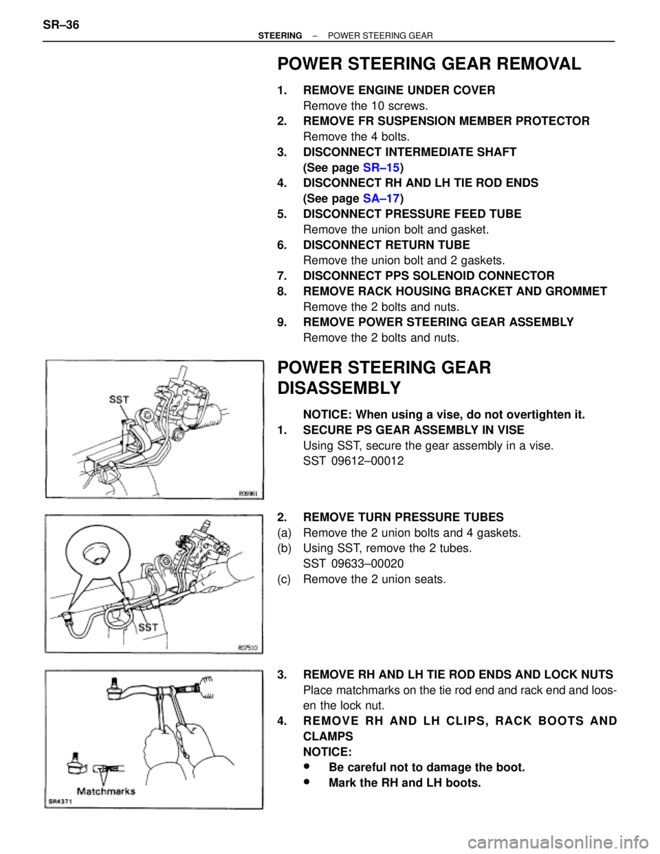
1. SECURE PS GEAR ASSEMBLY IN VISE
Using SST, secure the gear assembly in a vise.
SST 09612±00012
2. REMOVE TURN PRESSURE TUBES
(a) Remove the 2 union bolts and 4 gaskets.
(b) Using SST, remove the 2 tubes.
SST 09633±00020
(c) Remove the 2 union seats.
3. REMOVE RH AND LH TIE ROD ENDS AND LOCK NUTS
Place matchmarks on the tie rod end and rack end and loos-
en the lock nut.
4. REMOVE RH AND LH CLIPS, RACK BOOTS AND
CLAMPS
NOTICE:
wBe careful not to damage the boot.
wMark the RH and LH boots. SR±36
± STEERINGPOWER STEERING GEAR
Page 1676 of 2543
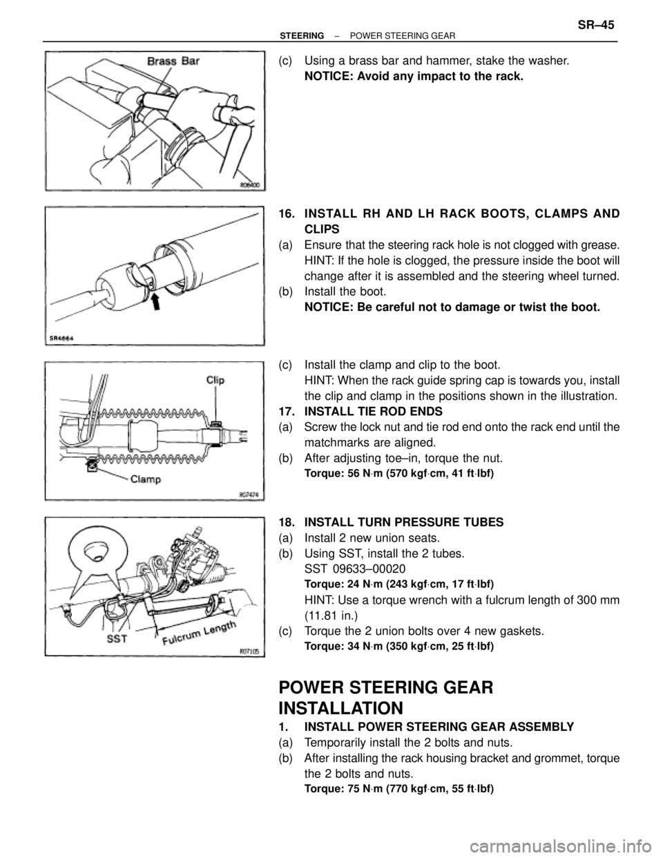
(c) Using a brass bar and hammer, stake the washer.
NOTICE: Avoid any impact to the rack.
16. INS TALL RH AND LH RACK BO O TS , CLAMP S AND
CLIPS
(a) Ensure that the steering rack hole is not clogged with grease.
HINT: If the hole is clogged, the pressure inside the boot will
change after it is assembled and the steering wheel turned.
(b) Install the boot.
NOTICE: Be careful not to damage or twist the boot.
(c) Install the clamp and clip to the boot.
HINT: When the rack guide spring cap is towards you, install
the clip and clamp in the positions shown in the illustration.
17. INSTALL TIE ROD ENDS
(a) Screw the lock nut and tie rod end onto the rack end until the
matchmarks are aligned.
(b) After adjusting toe±in, torque the nut.
Torque: 56 NVm (570 kgfVcm, 41 ftVlbf)
18. INSTALL TURN PRESSURE TUBES
(a) Install 2 new union seats.
(b) Using SST, install the 2 tubes.
SST 09633±00020
Torque: 24 NVm (243 kgfVcm, 17 ftVlbf)
HINT: Use a torque wrench with a fulcrum length of 300 mm
(11.81 in.)
(c) Torque the 2 union bolts over 4 new gaskets.
Torque: 34 NVm (350 kgfVcm, 25 ftVlbf)
POWER STEERING GEAR
INSTALLATION
1. INSTALL POWER STEERING GEAR ASSEMBLY
(a) Temporarily install the 2 bolts and nuts.
(b) After installing the rack housing bracket and grommet, torque
the 2 bolts and nuts.
Torque: 75 NVm (770 kgfVcm, 55 ftVlbf)
± STEERINGPOWER STEERING GEARSR±45
Page 1790 of 2543
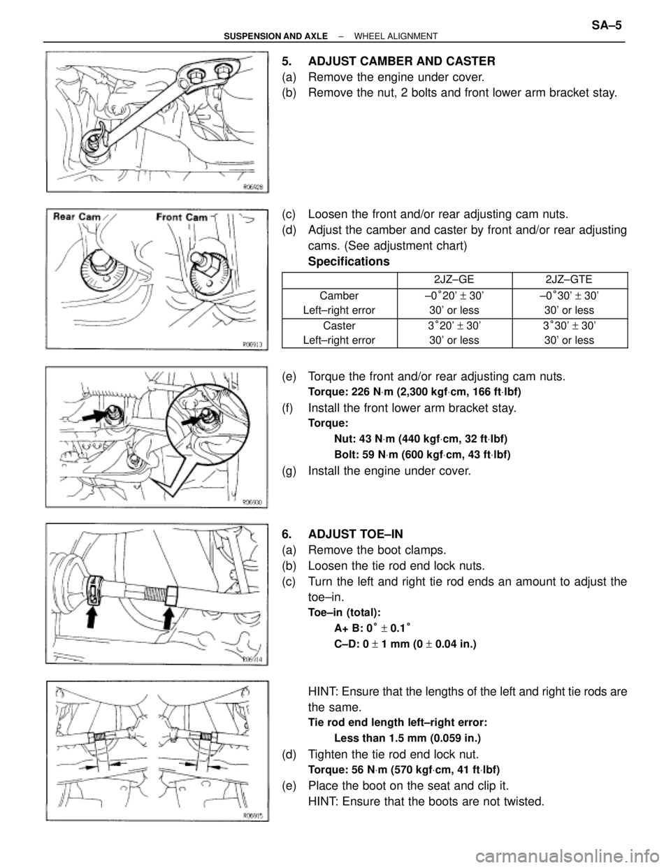
5. ADJUST CAMBER AND CASTER
(a) Remove the engine under cover.
(b) Remove the nut, 2 bolts and front lower arm bracket stay.
(c) Loosen the front and/or rear adjusting cam nuts.
(d) Adjust the camber and caster by front and/or rear adjusting
cams. (See adjustment chart)
Specifications
�������� ���������������� ��������2JZ±GE�������� ��������2JZ±GTE
�������� ��������Camber
Left±right error�������� ��������±0°20' + 30'
30' or less�������� ��������±0°30' + 30'
30' or less
�������� �
������� ��������Caster
Left±right error�������� �
������� ��������3°20' + 30'
30' or less�������� �
������� ��������3°30' + 30'
30' or less
(e) Torque the front and/or rear adjusting cam nuts.
Torque: 226 NVm (2,300 kgfVcm, 166 ftVlbf)
(f) Install the front lower arm bracket stay.
Torque:
Nut: 43 NVm (440 kgfVcm, 32 ftVlbf)
Bolt: 59 NVm (600 kgfVcm, 43 ftVlbf)
(g) Install the engine under cover.
6. ADJUST TOE±IN
(a) Remove the boot clamps.
(b) Loosen the tie rod end lock nuts.
(c) Turn the left and right tie rod ends an amount to adjust the
toe±in.
Toe±in (total):
A+ B: 0° + 0.1°
C±D: 0 + 1 mm (0 + 0.04 in.)
HINT: Ensure that the lengths of the left and right tie rods are
the same.
Tie rod end length left±right error:
Less than 1.5 mm (0.059 in.)
(d) Tighten the tie rod end lock nut.
Torque: 56 NVm (570 kgfVcm, 41 ftVlbf)
(e) Place the boot on the seat and clip it.
HINT: Ensure that the boots are not twisted.
± SUSPENSION AND AXLEWHEEL ALIGNMENTSA±5