Page 1258 of 2543

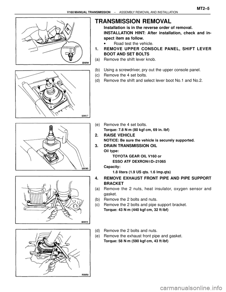
TRANSMISSION REMOVAL
Installation is in the reverse order of removal.
INSTALLATION HINT: After installation, check and in-
spect item as follow.
w Road test the vehicle.
1. REMOVE UPPER CONSOLE PANEL, SHIFT LEVER
BOOT AND SET BOLTS
(a) Remove the shift lever knob.
(b) Using a screwdriver, pry out the upper console panel.
(c) Remove the 4 set bolts.
(d) Remove the shift and select lever boot No.1 and No.2.
(e) Remove the 4 set bolts.
Torque: 7.8 NVm (80 kgfVcm, 69 in.Vlbf)
2. RAISE VEHICLE
NOTICE: Be sure the vehicle is securely supported.
3. DRAIN TRANSMISSION OIL
Oil type:
TOYOTA GEAR OIL V160 or
ESSO ATF DEXRON[D±21065
Capacity:
1.8 liters (1.9 US qts. 1.6 lmp.qts)
4. REMOVE EXHAUST FRONT PIPE AND PIPE SUPPORT
BRACKET
(a) Remove the 2 nuts, heat insulator, oxygen sensor and
gasket.
(b) Remove the 2 bolts and nuts.
(c) Remove the 2 bolts and pipe support bracket.
Torque: 43 NVm (440 kgfVcm, 32 ftVlbf)
(d) Remove the 2 bolts and nuts.
(e) Remove the exhaust front pipe and gasket.
Torque: 58 NVm (590 kgfVcm, 43 ftVlbf)
± V160 MANUAL TRANSMISSIONASSEMBLY REMOVAL AND INSTALLATIONMT2±5
Page 1274 of 2543
TRANSMISSION REMOVAL
Installation is in the reverse order of removal.
INSTALLATION HINT: After installation, check and inspect
item as follows.
wRoad test the vehicle.
1. REMOVE FAN SHROUD SET BOLTS
Remove the 5 bolts.
2. REMOVE UPPER CONSOLE PANEL, SHIFT LEVER
BOOT AND MOUNTING BOLTS
(a) Remove the shift lever knob.
(b) Using a screwdriver, pry out the upper console panel.
(c) Remove the 4 mounting bolts.
(d) Remove the shift and select lever boot No.1 and No.2.
(e) Remove the 4 mounting bolts.
Torque: 7.8 NVm (80 kgfVcm, 69 in.Vlbf)
3. RAISE VEHICLE
NOTICE: Be sure the vehicle is securely supported.
4. DRAIN TRANSMISSION OIL
Oil grade:
API GL±3, GL±4 or GL±5
Viscosity:
SAE 75W±90
Capacity:
2.6 liters (2.7 US qts, 2.3 Imp.qts)
5. REMOVE EXHAUST FRONT PIPE AND PIPE SUPPORT
BRACKET
(a) Remove the 2 nuts, cover and oxygen sensor.
Torque: 18 NVm (180 kgfVcm, 13 ftVlbf)
MT1±8± W58 MANUAL TRANSMISSIONASSEMBLY REMOVAL AND INSTALLATION
Page 1279 of 2543

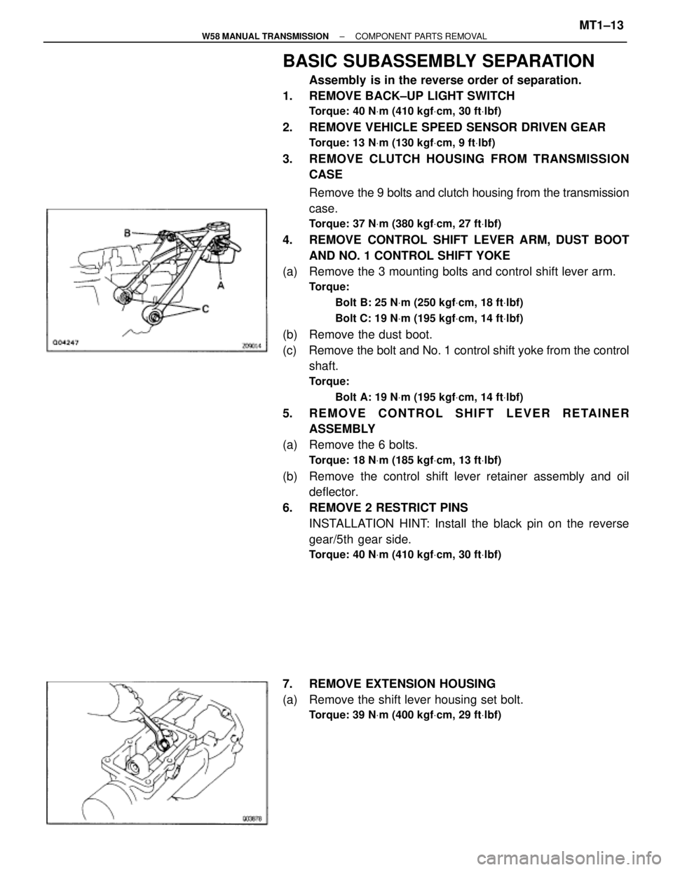
BASIC SUBASSEMBLY SEPARATION
Assembly is in the reverse order of separation.
1. REMOVE BACK±UP LIGHT SWITCH
Torque: 40 NVm (410 kgfVcm, 30 ftVlbf)
2. REMOVE VEHICLE SPEED SENSOR DRIVEN GEAR
Torque: 13 NVm (130 kgfVcm, 9 ftVlbf)
3. REMOVE CLUTCH HOUSING FROM TRANSMISSION
CASE
Remove the 9 bolts and clutch housing from the transmission
case.
Torque: 37 NVm (380 kgfVcm, 27 ftVlbf)
4. REMOVE CONTROL SHIFT LEVER ARM, DUST BOOT
AND NO. 1 CONTROL SHIFT YOKE
(a) Remove the 3 mounting bolts and control shift lever arm.
Torque:
Bolt B: 25 NVm (250 kgfVcm, 18 ftVlbf)
Bolt C: 19 NVm (195 kgfVcm, 14 ftVlbf)
(b) Remove the dust boot.
(c) Remove the bolt and No. 1 control shift yoke from the control
shaft.
Torque:
Bolt A: 19 NVm (195 kgfVcm, 14 ftVlbf)
5. REMOVE CONTROL SHIFT LEVER RETAINER
ASSEMBLY
(a) Remove the 6 bolts.
Torque: 18 NVm (185 kgfVcm, 13 ftVlbf)
(b) Remove the control shift lever retainer assembly and oil
deflector.
6. REMOVE 2 RESTRICT PINS
INSTALLATION HINT: Install the black pin on the reverse
gear/5th gear side.
Torque: 40 NVm (410 kgfVcm, 30 ftVlbf)
7. REMOVE EXTENSION HOUSING
(a) Remove the shift lever housing set bolt.
Torque: 39 NVm (400 kgfVcm, 29 ftVlbf)
± W58 MANUAL TRANSMISSIONCOMPONENT PARTS REMOVALMT1±13
Page 1339 of 2543
7. SET NO.1 CYLINDER TO TDC/COMPRESSION
(a) Turn the crankshaft pulley, and align its groove with timing
mark ºOº of the No.1 timing belt cover.
NOTICE: Always turn the crankshaft clockwise.
(b) Check that the timing marks of the camshaft timing pulleys
are aligned with the timing marks of the No.4 timing belt
cover.
If not, turn the crankshaft 1 revolution (360°).
8. REMOVE TIMING BELT FROM CAMSHAFT TIMING
PULLEYS
HINT (Re±using timing belt): Place matchmarks on the timing
belt and camshaft timing pulleys as shown in the illustration.
(a) Alternately loosen the 2 bolts, and remove them, the
tensioner and dust boot.
(b) Disconnect the timing belt from the camshaft timing pulleys.
± ENGINEENGINE MECHANICALEG±25
Page 1346 of 2543

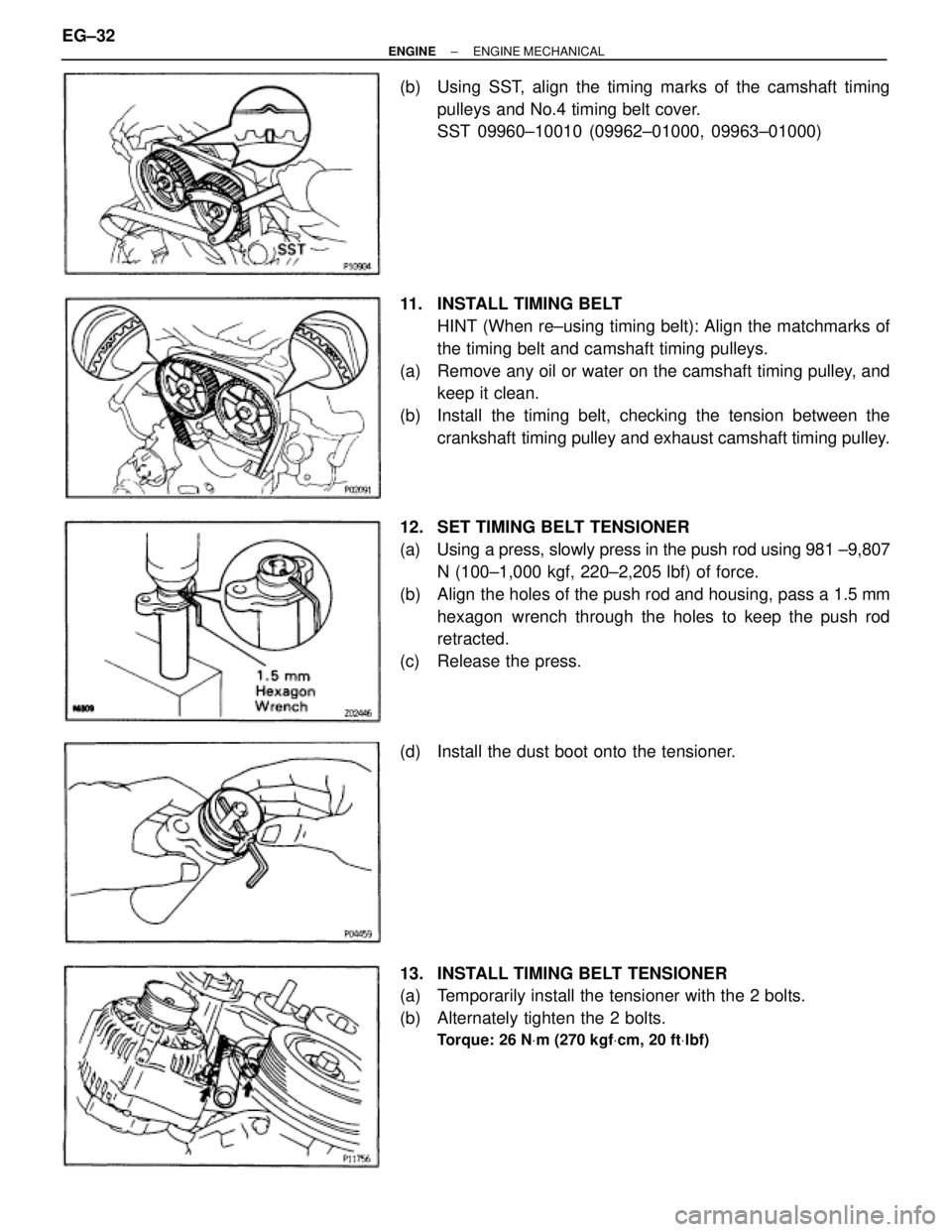
(b) Using SST, align the timing marks of the camshaft timing
pulleys and No.4 timing belt cover.
SST 09960±10010 (09962±01000, 09963±01000)
11. INSTALL TIMING BELT
HINT (When re±using timing belt): Align the matchmarks of
the timing belt and camshaft timing pulleys.
(a) Remove any oil or water on the camshaft timing pulley, and
keep it clean.
(b) Install the timing belt, checking the tension between the
crankshaft timing pulley and exhaust camshaft timing pulley.
12. SET TIMING BELT TENSIONER
(a) Using a press, slowly press in the push rod using 981 ±9,807
N (100±1,000 kgf, 220±2,205 lbf) of force.
(b) Align the holes of the push rod and housing, pass a 1.5 mm
hexagon wrench through the holes to keep the push rod
retracted.
(c) Release the press.
(d) Install the dust boot onto the tensioner.
13. INSTALL TIMING BELT TENSIONER
(a) Temporarily install the tensioner with the 2 bolts.
(b) Alternately tighten the 2 bolts.
Torque: 26 NVm (270 kgfVcm, 20 ftVlbf)
EG±32± ENGINEENGINE MECHANICAL
Page 1396 of 2543
19. DISCONNECT ENGINE WIRE FROM CABIN
(a) Remove the scuff plate.
(b) Take out the front side of the floor carpet.
(c) Remove the 2 nuts and ECM protector.
(d) Remove the nut, and disconnect the ECM from the floor
panel.
(e) Disconnect the 2 connectors from the ECM.
(f) Disconnect the connector from the instrument panel wire.
(g) Disconnect the connector from the connector cassette.
(h) Pull out the engine wire from the cabin.
20. M/T:
REMOVE UPPER CONSOLE PANEL, SHIFT LEVER
BOOTS AND HOLDING BOLTS
(a) Remove the shift lever knob.
(b) Using a screwdriver, pry out the upper console panel. EG±82
± ENGINEENGINE MECHANICAL
Page 1397 of 2543
(c) Remove the 4 bolts holding the lever boot to the transmission
cover.
(d) Remove the shift and select lever boots.
(e) Remove the 4 bolts holding the shift lever to the shift lever
retainer.
21. M/T:
DISCONNECT CLUTCH RELEASE CYLINDER AND
GROUND STRAP FROM TRANSMISSION
(a) Remove the 2 bolts and clutch release cylinder.
(b) Remove the bolt, and disconnect the ground strap.
22. REMOVE NO.2 EXHAUST PIPE
(a) Remove the 2 bolts and nuts holding the No.2 front exhaust
pipe to the front exhaust pipe.
(b) Remove the 2 bolts and pipe support bracket.
(c) Remove the gasket, and disconnect the front exhaust pipe.
(d) Remove the 4 nuts, No.2 front exhaust pipe and 2 gaskets.
23. REMOVE EXHAUST PIPE HEAT INSULATOR
24. REMOVE PROPELLER SHAFT
(See propeller shaft removal in Propeller Shaft)
± ENGINEENGINE MECHANICALEG±83
Page 1403 of 2543
20. DISCONNECT ENGINE WIRE FROM CABIN
(a) Remove the scuff plate.
(b) Take out the front side of the floor carpet.
(c) Remove the 2 nuts and ECM protector.
(d) Remove the nut, and disconnect the ECM from the floor
panel.
(e) Disconnect the 2 connectors from the ECM.
(f) Disconnect the connector from the TRAC ECU.
(g) Disconnect the connector from the instrument panel wire.
(h) Disconnect the connectors from the connector cassette.
(j) Pull out the engine wire from the cabin.
21. M/T:
REMOVE UPPER CONSOLE PANEL, SHIFT LEVER
BOOTS AND HOLDING BOLTS
(a) Remove the shift lever knob.
(b) Using a screwdriver, pry out the upper console panel.
± ENGINEENGINE MECHANICALEG±89