Page 1247 of 2543
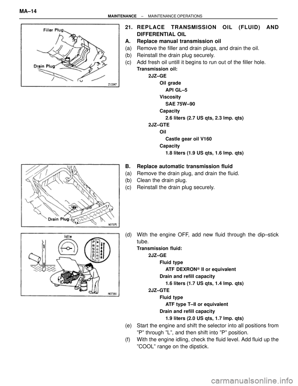
21. REPLACE TRANSMISSION OIL (FLUID) AND
DIFFERENTIAL OIL
A. Replace manual transmission oil
(a) Remove the filler and drain plugs, and drain the oil.
(b) Reinstall the drain plug securely.
(c) Add fresh oil untill it begins to run out of the filler hole.
Transmission oil:
2JZ±GE
Oil grade
API GL±5
Viscosity
SAE 75W±90
Capacity
2.6 liters (2.7 US qts, 2.3 lmp. qts)
2JZ±GTE
Oil
Castle gear oil V160
Capacity
1.8 liters (1.9 US qts, 1.6 lmp. qts)
B. Replace automatic transmission fluid
(a) Remove the drain plug, and drain the fluid.
(b) Clean the drain plug.
(c) Reinstall the drain plug securely.
(d) With the engine OFF, add new fluid through the dip±stick
tube.
Transmission fluid:
2JZ±GE
Fluid type
ATF DEXRON® II or equivalent
Drain and refill capacity
1.6 liters (1.7 US qts, 1.4 lmp. qts)
2JZ±GTE
Fluid type
ATF type T±II or equivalent
Drain and refill capacity
1.9 liters (2.0 US qts, 1.7 lmp. qts)
(e) Start the engine and shift the selector into all positions from
ºPº through ºLº, and then shift into ºPº position.
(f) With the engine idling, check the fluid level. Add fluid up the
ºCOOLº range on the dipstick. MA±14
± MAINTENANCEMAINTENANCE OPERATIONS
Page 1248 of 2543
(g) Check that the fluid level is in the ºHOTº range at the normal
operating temperature (70±80°C (158±176°F)) and add as
necessary.
NOTICE: Do not overfill.
C. Replace differential oil
(a) Remove the filler and drain plugs, and drain the oil.
(b) Clean the drain plug.
(c) Reinstall the drain plug securely.
(d) Add new oil until it begins to run out of the filler hole.
Differential oil:
Oil grade
API GL±5
Viscosity
Above±185C (05F) SAE 90
Below±185C (05F) SAE 80W±90 or 80W
Capacity
1.35 liters (1.43 US qts, 1.19 lmp. qts)
(e) Reinstall the filler plug securely.
± MAINTENANCEMAINTENANCE OPERATIONSMA±15
Page 1251 of 2543

18. BRAKE PEDAL
(a) Check that pedal for smooth operation.
(b) Check that the pedal has the proper reserve
distance and freeplay.
(c) Check the brake booster function.
19. BRAKES
At a safe place, check that the brakes do not
pull to one side when applied.
20. PARKING BRAKE
(a) Check that the pedal has the proper travel.
(b) On a safe incline, check that the vehicle is
held securely with only the parking brake
applied.
21. AUTOMATIC TRANSMISSION PARK
MECHANISM
(a) Check the lock release button of the selector
lever for proper and smooth operation.
(b) On a safe incline, check that the vehicle is
held securely with the selector lever in the ºPº
position and all brakes released.
UNDER HOOD
22. WINDSHIELD WASHER FLUID
Check that there is sufficient fluid in the tank.
23. ENGINE COOLANT LEVEL
Check that the coolant level is between the
LEVEL lines on the see±through reservoir at
normal temperature (20°C (68°F)).
24. RADIATOR AND HOSES
(a) Check that the front of the radiator is clean
and not blocked with leaves, dirt or bugs.
(b) Check the hoses for cracks, kinks, rot or
loose connections.
25. BATTERY ELECTROLYTE LEVEL
Check the indicator.
When the indicator color is blue, the condition
is satisfactory. A red color indicates that dis-
tilled water must be added, and white indi-
cates that charging is necessary.
26. BRAKE FLUID LEVEL
Check that the brake fluid level is near the up-
per level line on the see±through reservoir.27. ENGINE DRIVE BELT
Check drive belt for fraying, cracks, wear or
oil contamination.
28. ENGINE OIL LEVEL
Check that level on the dipstick with the en-
gine turned off.
29. POWER STEERING FLUID LEVEL
Check the level on the dipstick.
The level should be in the ºHOTº or ºCOLDº
range depending on the fluid temperature.
30. A U TO M AT I C TRANSMISSION FLUID
LEVEL
(a) Park the vehicle on a level surface.
(b) With the engine idling and the parking and
foot brake applied, shift the selector into all
positions from ºPº to ºLº, and then shift into ºPº
position.
(c) Turn and pull out the dipstick and wipe off the
fluid with a clean rag.
Re±insert the dipstick fully and check that the
fluid level is in the ºHOTº range.
(d) Perform this check with the fluid at normal
driving temperature (70±80°C (158±176°F)).
If the level is at the low side, add fluid.
NOTICE: Do not overfill.
HINT: Wait about 30 minutes before checking
the fluid level after extended driving at high
speeds in hot weather, driving in heavy traffic
or with a trailer.
31. EXHAUST SYSTEM
Visually inspect for cracks, holes or loose
supports.
If any change in the sound of the exhaust or
smell of the exhaust fumes is noticed, have
the cause located and correted. MA±18
± MAINTENANCEGENERAL MAINTENANCE
Page 1255 of 2543
MT2±8MT2±4
Noise
Jumps out of gear
Trouble
Parts
Name
See page
Hard to shift or will not shift
Oil leakage
Oil (Level low)Oil seal (Worn or damaged)Gasket (Damaged)Oil (Level too high)Oil (Wrong)Locking ball spring (Damaged)Control cable (Family)Shift key spring (Damaged)O±Ring (Worn or damaged)Gear (Worn or damaged)Shift fork (Worn)Bearing (Worn or damaged)Synchronizer ring (Worn or damaged)Flywheel damper
MT2±8CL
Section
SSM (SPECIAL SERVICE MATERIALS)������������� �
������������ �
������������ �
������������ �������������
08833±00080
�������������� �
������������� �
������������� �
������������� ��������������
Adhesive 1344,
THREE BOND 1344,
LOCTITE 242 or equivalent
����������� �
���������� �
���������� �
���������� �����������
Companion flange lock nut
Vehicle speed sensor set bolt
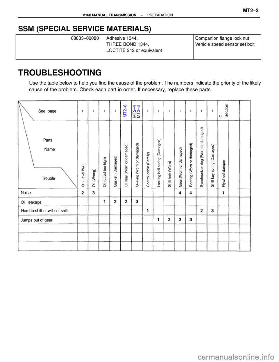
TROUBLESHOOTING
Use the table below to help you find the cause of the problem. The numbers indicate the priority of the likely
cause of the problem. Check each part in order. If necessary, replace these parts.
± V160 MANUAL TRANSMISSIONPREPARATIONMT2±3
Page 1256 of 2543
MT2±8MT2±4
Noise
Jumps out of gear
Trouble
Parts
Name
See page
Hard to shift or will not shift
Oil leakage
Oil (Level low)Oil seal (Worn or damaged)Gasket (Damaged)Oil (Level too high)Oil (Wrong)Locking ball spring (Damaged)Control cable (Family)Shift key spring (Damaged)O±Ring (Worn or damaged)Gear (Worn or damaged)Shift fork (Worn)Bearing (Worn or damaged)Synchronizer ring (Worn or damaged)Flywheel damper
MT2±8CL
Section
SSM (SPECIAL SERVICE MATERIALS)������������� �
������������ �
������������ �
������������ �������������
08833±00080
�������������� �
������������� �
������������� �
������������� ��������������
Adhesive 1344,
THREE BOND 1344,
LOCTITE 242 or equivalent
����������� �
���������� �
���������� �
���������� �����������
Companion flange lock nut
Vehicle speed sensor set bolt
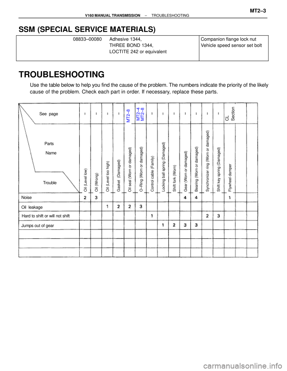
TROUBLESHOOTING
Use the table below to help you find the cause of the problem. The numbers indicate the priority of the likely
cause of the problem. Check each part in order. If necessary, replace these parts.
± V160 MANUAL TRANSMISSIONTROUBLESHOOTINGMT2±3
Page 1271 of 2543
MT1±11MT1±26,34MT2±2MT1±24,26
34MT1±11MT1±11MT1±11MT1±12MT1±12MT1±12
Oil (Level low)O±Ring (Worn or damaged)Oil seal (Worn or damaged)Gasket (Damaged)Oil (Level too high)Oil (Wrong)Bearing (Worn or damaged)Gear (Worn or damaged)Shift fork (Worn)Locking ball spring (Damaged)O±Ring (Worn or damaged)Shifting key spring (Damaged)Synchronizer ring (Worn or damaged)
Noise
Jumps out of gear
Trouble
Parts
Name
See page
Hard to shift or will not shift
Oil leakage
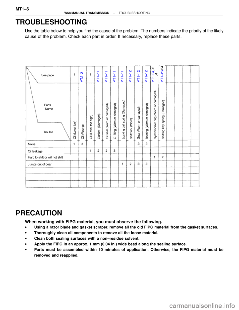
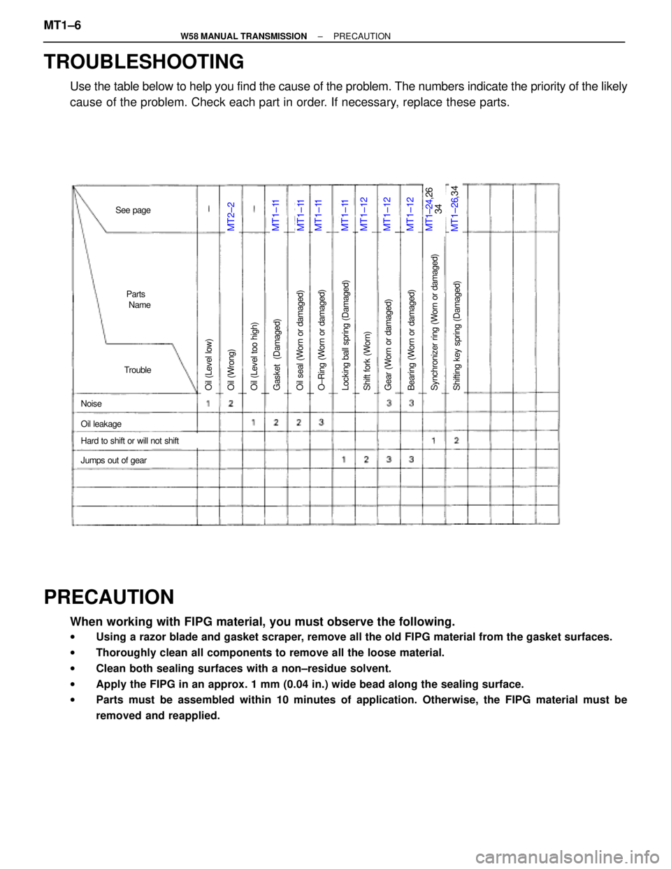
TROUBLESHOOTING
Use the table below to help you find the cause of the problem. The numbers indicate the priority of the likely
cause of the problem. Check each part in order. If necessary, replace these parts.
PRECAUTION
When working with FIPG material, you must observe the following.
wUsing a razor blade and gasket scraper, remove all the old FIPG material from the gasket surfaces.
wThoroughly clean all components to remove all the loose material.
wClean both sealing surfaces with a non±residue solvent.
wApply the FIPG in an approx. 1 mm (0.04 in.) wide bead along the sealing surface.
wParts must be assembled within 10 minutes of application. Otherwise, the FIPG material must be
removed and reapplied.
MT1±6± W58 MANUAL TRANSMISSIONTROUBLESHOOTING
Page 1272 of 2543
MT1±11MT1±26,34MT2±2MT1±24,26
34MT1±11MT1±11MT1±11MT1±12MT1±12MT1±12
Oil (Level low)O±Ring (Worn or damaged)Oil seal (Worn or damaged)Gasket (Damaged)Oil (Level too high)Oil (Wrong)Bearing (Worn or damaged)Gear (Worn or damaged)Shift fork (Worn)Locking ball spring (Damaged)O±Ring (Worn or damaged)Shifting key spring (Damaged)Synchronizer ring (Worn or damaged)
Noise
Jumps out of gear
Trouble
Parts
Name
Hard to shift or will not shift
Oil leakage
See page
TROUBLESHOOTING
Use the table below to help you find the cause of the problem. The numbers indicate the priority of the likely
cause of the problem. Check each part in order. If necessary, replace these parts.
PRECAUTION
When working with FIPG material, you must observe the following.
wUsing a razor blade and gasket scraper, remove all the old FIPG material from the gasket surfaces.
wThoroughly clean all components to remove all the loose material.
wClean both sealing surfaces with a non±residue solvent.
wApply the FIPG in an approx. 1 mm (0.04 in.) wide bead along the sealing surface.
wParts must be assembled within 10 minutes of application. Otherwise, the FIPG material must be
removed and reapplied.
MT1±6± W58 MANUAL TRANSMISSIONPRECAUTION
Page 1442 of 2543
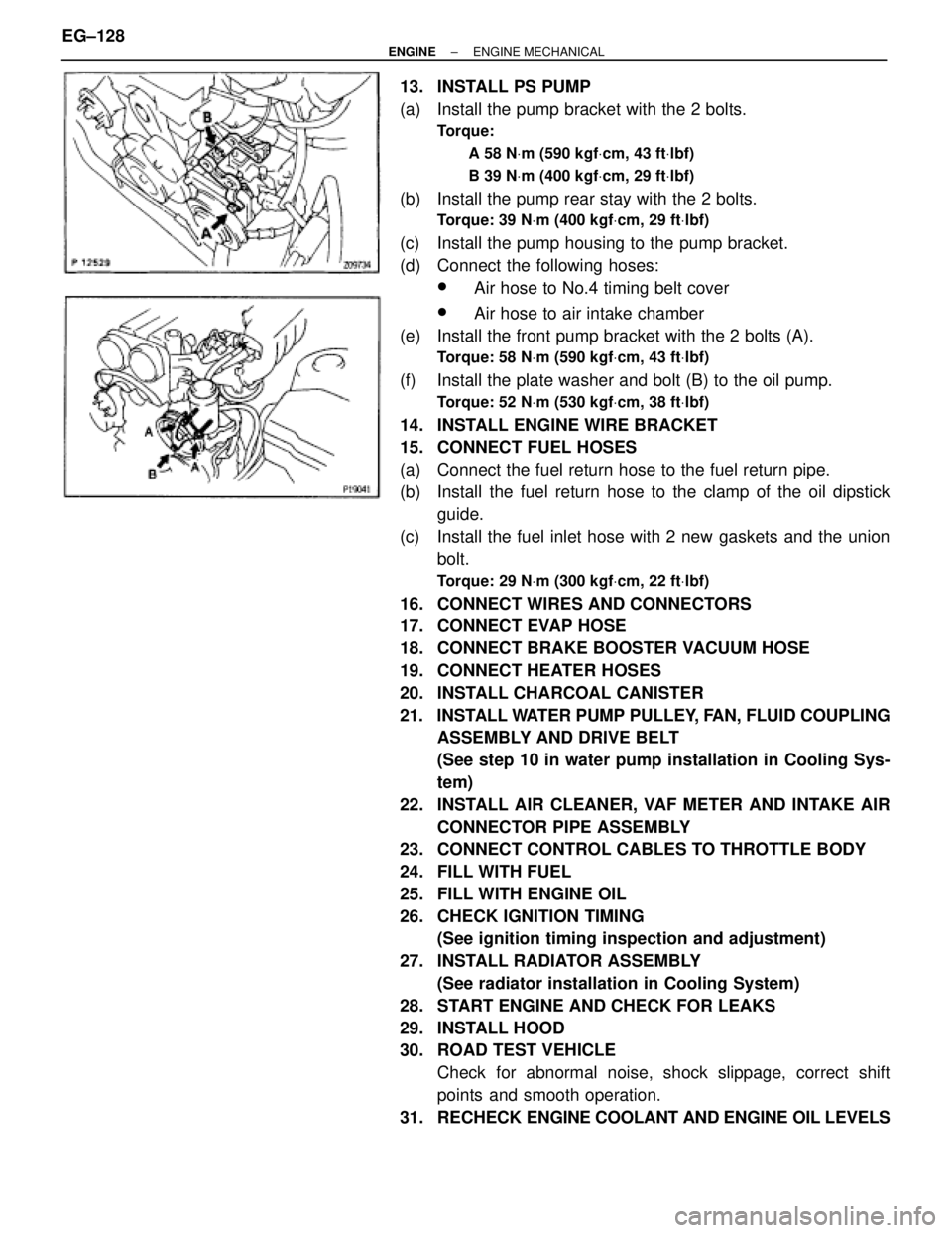
13. INSTALL PS PUMP
(a) Install the pump bracket with the 2 bolts.
Torque:
A 58 NVm (590 kgfVcm, 43 ftVlbf)
B 39 NVm (400 kgfVcm, 29 ftVlbf)
(b) Install the pump rear stay with the 2 bolts.
Torque: 39 NVm (400 kgfVcm, 29 ftVlbf)
(c) Install the pump housing to the pump bracket.
(d) Connect the following hoses:
wAir hose to No.4 timing belt cover
wAir hose to air intake chamber
(e) Install the front pump bracket with the 2 bolts (A).
Torque: 58 NVm (590 kgfVcm, 43 ftVlbf)
(f) Install the plate washer and bolt (B) to the oil pump.
Torque: 52 NVm (530 kgfVcm, 38 ftVlbf)
14. INSTALL ENGINE WIRE BRACKET
15. CONNECT FUEL HOSES
(a) Connect the fuel return hose to the fuel return pipe.
(b) Install the fuel return hose to the clamp of the oil dipstick
guide.
(c) Install the fuel inlet hose with 2 new gaskets and the union
bolt.
Torque: 29 NVm (300 kgfVcm, 22 ftVlbf)
16. CONNECT WIRES AND CONNECTORS
17. CONNECT EVAP HOSE
18. CONNECT BRAKE BOOSTER VACUUM HOSE
19. CONNECT HEATER HOSES
20. INSTALL CHARCOAL CANISTER
21. INSTALL WATER PUMP PULLEY, FAN, FLUID COUPLING
ASSEMBLY AND DRIVE BELT
(See step 10 in water pump installation in Cooling Sys-
tem)
22. INSTALL AIR CLEANER, VAF METER AND INTAKE AIR
CONNECTOR PIPE ASSEMBLY
23. CONNECT CONTROL CABLES TO THROTTLE BODY
24. FILL WITH FUEL
25. FILL WITH ENGINE OIL
26. CHECK IGNITION TIMING
(See ignition timing inspection and adjustment)
27. INSTALL RADIATOR ASSEMBLY
(See radiator installation in Cooling System)
28. START ENGINE AND CHECK FOR LEAKS
29. INSTALL HOOD
30. ROAD TEST VEHICLE
Check for abnormal noise, shock slippage, correct shift
points and smooth operation.
31. RECHECK ENGINE COOLANT AND ENGINE OIL LEVELS EG±128
± ENGINEENGINE MECHANICAL