Page 1279 of 2543
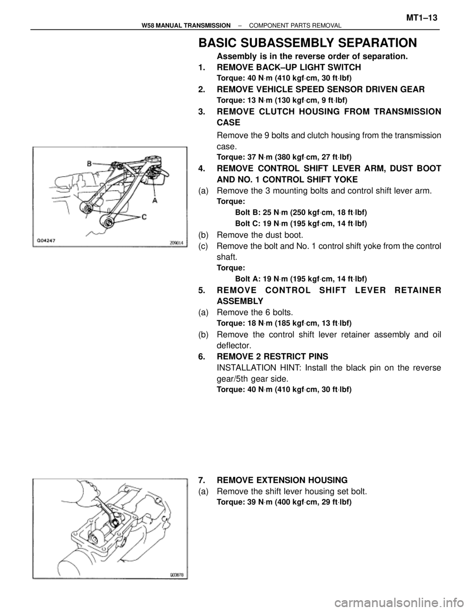
BASIC SUBASSEMBLY SEPARATION
Assembly is in the reverse order of separation.
1. REMOVE BACK±UP LIGHT SWITCH
Torque: 40 NVm (410 kgfVcm, 30 ftVlbf)
2. REMOVE VEHICLE SPEED SENSOR DRIVEN GEAR
Torque: 13 NVm (130 kgfVcm, 9 ftVlbf)
3. REMOVE CLUTCH HOUSING FROM TRANSMISSION
CASE
Remove the 9 bolts and clutch housing from the transmission
case.
Torque: 37 NVm (380 kgfVcm, 27 ftVlbf)
4. REMOVE CONTROL SHIFT LEVER ARM, DUST BOOT
AND NO. 1 CONTROL SHIFT YOKE
(a) Remove the 3 mounting bolts and control shift lever arm.
Torque:
Bolt B: 25 NVm (250 kgfVcm, 18 ftVlbf)
Bolt C: 19 NVm (195 kgfVcm, 14 ftVlbf)
(b) Remove the dust boot.
(c) Remove the bolt and No. 1 control shift yoke from the control
shaft.
Torque:
Bolt A: 19 NVm (195 kgfVcm, 14 ftVlbf)
5. REMOVE CONTROL SHIFT LEVER RETAINER
ASSEMBLY
(a) Remove the 6 bolts.
Torque: 18 NVm (185 kgfVcm, 13 ftVlbf)
(b) Remove the control shift lever retainer assembly and oil
deflector.
6. REMOVE 2 RESTRICT PINS
INSTALLATION HINT: Install the black pin on the reverse
gear/5th gear side.
Torque: 40 NVm (410 kgfVcm, 30 ftVlbf)
7. REMOVE EXTENSION HOUSING
(a) Remove the shift lever housing set bolt.
Torque: 39 NVm (400 kgfVcm, 29 ftVlbf)
± W58 MANUAL TRANSMISSIONCOMPONENT PARTS REMOVALMT1±13
Page 1281 of 2543
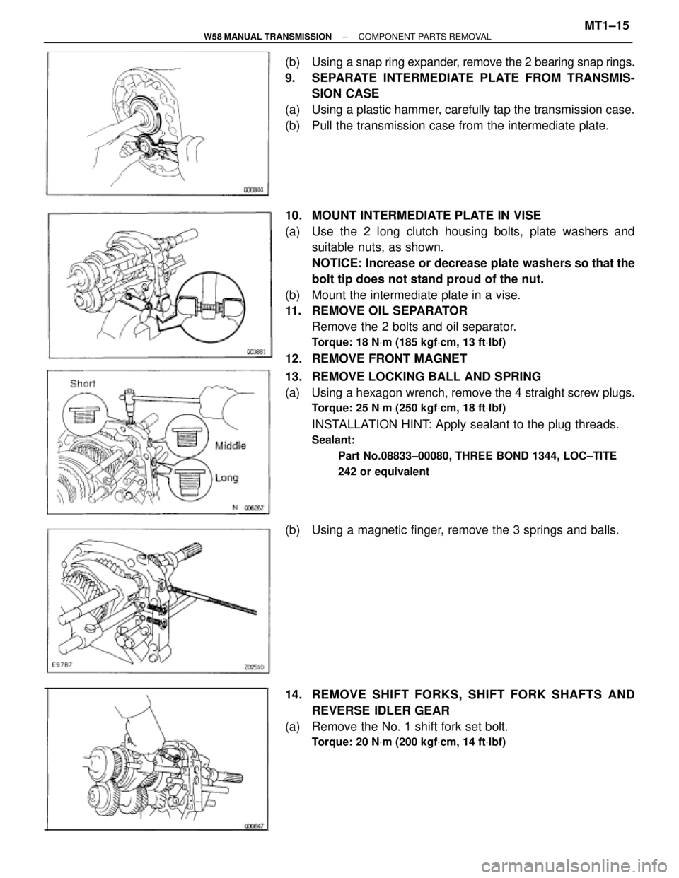
(b) Using a snap ring expander, remove the 2 bearing snap rings.
9. SEPARATE INTERMEDIATE PLATE FROM TRANSMIS-
SION CASE
(a) Using a plastic hammer, carefully tap the transmission case.
(b) Pull the transmission case from the intermediate plate.
10. MOUNT INTERMEDIATE PLATE IN VISE
(a) Use the 2 long clutch housing bolts, plate washers and
suitable nuts, as shown.
NOTICE: Increase or decrease plate washers so that the
bolt tip does not stand proud of the nut.
(b) Mount the intermediate plate in a vise.
11. REMOVE OIL SEPARATOR
Remove the 2 bolts and oil separator.
Torque: 18 NVm (185 kgfVcm, 13 ftVlbf)
12. REMOVE FRONT MAGNET
13. REMOVE LOCKING BALL AND SPRING
(a) Using a hexagon wrench, remove the 4 straight screw plugs.
Torque: 25 NVm (250 kgfVcm, 18 ftVlbf)
INSTALLATION HINT: Apply sealant to the plug threads.
Sealant:
Part No.08833±00080, THREE BOND 1344, LOC±TITE
242 or equivalent
(b) Using a magnetic finger, remove the 3 springs and balls.
14. REMOVE SHIFT FORKS, SHIFT FORK SHAFTS AND
REVERSE IDLER GEAR
(a) Remove the No. 1 shift fork set bolt.
Torque: 20 NVm (200 kgfVcm, 14 ftVlbf)
± W58 MANUAL TRANSMISSIONCOMPONENT PARTS REMOVALMT1±15
Page 1285 of 2543
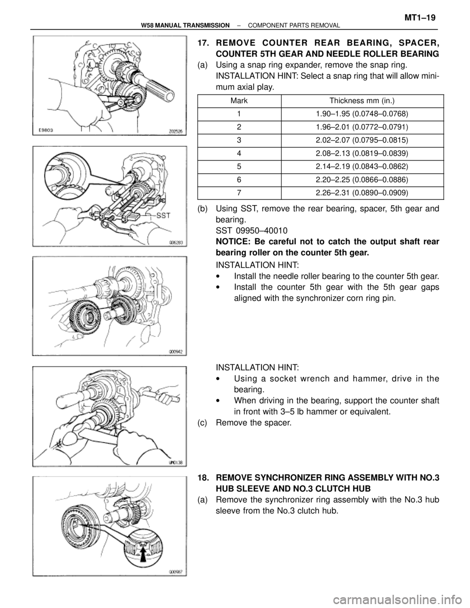
17. REMOVE COUNTER REAR BEARING, SPACER,
COUNTER 5TH GEAR AND NEEDLE ROLLER BEARING
(a) Using a snap ring expander, remove the snap ring.
INSTALLATION HINT: Select a snap ring that will allow mini-
mum axial play.
�������� �
������� ��������Mark
��������������� �
�������������� ���������������Thickness mm (in.)
�������� ��������1��������������� ���������������1.90±1.95 (0.0748±0.0768)
�������� ��������2��������������� ���������������1.96±2.01 (0.0772±0.0791)
�������� ��������3��������������� ���������������2.02±2.07 (0.0795±0.0815)
�������� ��������4��������������� ���������������2.08±2.13 (0.0819±0.0839)
�������� ��������5��������������� ���������������2.14±2.19 (0.0843±0.0862)
�������� ��������6��������������� ���������������2.20±2.25 (0.0866±0.0886)�������� ��������7��������������� ���������������2.26±2.31 (0.0890±0.0909)
(b) Using SST, remove the rear bearing, spacer, 5th gear and
bearing.
SST 09950±40010
NOTICE: Be careful not to catch the output shaft rear
bearing roller on the counter 5th gear.
INSTALLATION HINT:
wInstall the needle roller bearing to the counter 5th gear.
wInstall the counter 5th gear with the 5th gear gaps
aligned with the synchronizer corn ring pin.
INSTALLATION HINT:
wUsing a socket wrench and hammer, drive in the
bearing.
wWhen driving in the bearing, support the counter shaft
in front with 3±5 lb hammer or equivalent.
(c) Remove the spacer.
18. REMOVE SYNCHRONIZER RING ASSEMBLY WITH NO.3
HUB SLEEVE AND NO.3 CLUTCH HUB
(a) Remove the synchronizer ring assembly with the No.3 hub
sleeve from the No.3 clutch hub.
± W58 MANUAL TRANSMISSIONCOMPONENT PARTS REMOVALMT1±19
Page 1286 of 2543
(b) Remove the spacer.
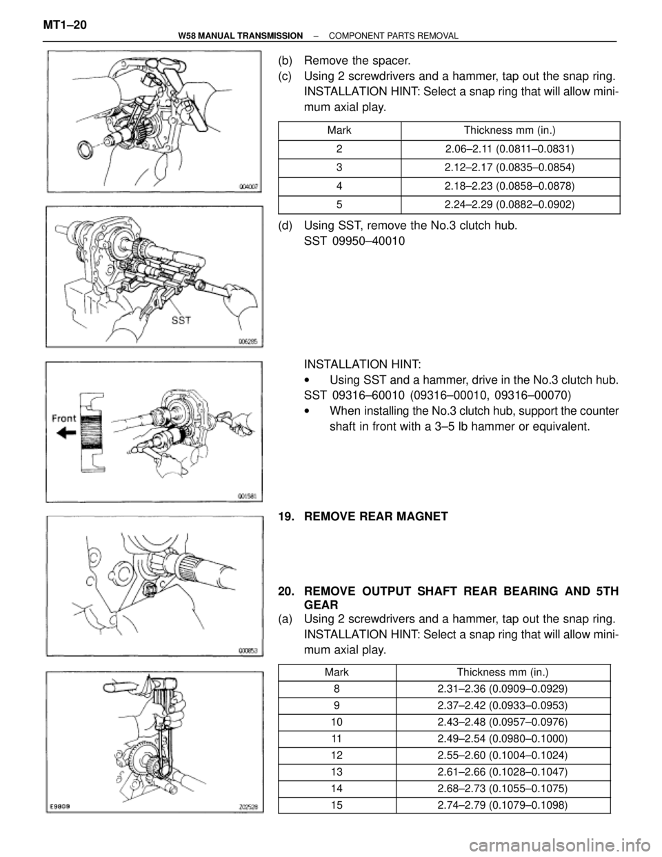
(c) Using 2 screwdrivers and a hammer, tap out the snap ring.
INSTALLATION HINT: Select a snap ring that will allow mini-
mum axial play.
��������� ���������Mark�������������� ��������������Thickness mm (in.)
��������� ���������2�������������� ��������������2.06±2.11 (0.0811±0.0831)
��������� ���������3�������������� ��������������2.12±2.17 (0.0835±0.0854)
��������� ���������4�������������� ��������������2.18±2.23 (0.0858±0.0878)��������� ���������5�������������� ��������������2.24±2.29 (0.0882±0.0902)
(d) Using SST, remove the No.3 clutch hub.
SST 09950±40010
INSTALLATION HINT:
wUsing SST and a hammer, drive in the No.3 clutch hub.
SST 09316±60010 (09316±00010, 09316±00070)
wWhen installing the No.3 clutch hub, support the counter
shaft in front with a 3±5 lb hammer or equivalent.
19. REMOVE REAR MAGNET
20. REMOVE OUTPUT SHAFT REAR BEARING AND 5TH
GEAR
(a) Using 2 screwdrivers and a hammer, tap out the snap ring.
INSTALLATION HINT: Select a snap ring that will allow mini-
mum axial play.
�������� ��������
Mark
�������������� ��������������
Thickness mm (in.)�������� ��������
8
�������������� ��������������
2.31±2.36 (0.0909±0.0929)�������� ��������
9
�������������� ��������������
2.37±2.42 (0.0933±0.0953)�������� ��������
10
�������������� ��������������
2.43±2.48 (0.0957±0.0976)�������� ��������
11
�������������� ��������������
2.49±2.54 (0.0980±0.1000)�������� ��������
12
�������������� ��������������
2.55±2.60 (0.1004±0.1024)�������� ��������
13
�������������� ��������������
2.61±2.66 (0.1028±0.1047)�������� ��������
14
�������������� ��������������
2.68±2.73 (0.1055±0.1075)�������� ��������
15
�������������� ��������������
2.74±2.79 (0.1079±0.1098)
MT1±20± W58 MANUAL TRANSMISSIONCOMPONENT PARTS REMOVAL
Page 1293 of 2543
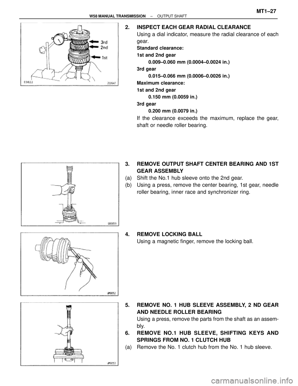
2. INSPECT EACH GEAR RADIAL CLEARANCE
Using a dial indicator, measure the radial clearance of each
gear.
Standard clearance:
1st and 2nd gear
0.009±0.060 mm (0.0004±0.0024 in.)
3rd gear
0.015±0.066 mm (0.0006±0.0026 in.)
Maximum clearance:
1st and 2nd gear
0.150 mm (0.0059 in.)
3rd gear
0.200 mm (0.0079 in.)
If the clearance exceeds the maximum, replace the gear,
shaft or needle roller bearing.
3. REMOVE OUTPUT SHAFT CENTER BEARING AND 1ST
GEAR ASSEMBLY
(a) Shift the No.1 hub sleeve onto the 2nd gear.
(b) Using a press, remove the center bearing, 1st gear, needle
roller bearing, inner race and synchronizer ring.
4. REMOVE LOCKING BALL
Using a magnetic finger, remove the locking ball.
5. REMOVE NO. 1 HUB SLEEVE ASSEMBLY, 2 ND GEAR
AND NEEDLE ROLLER BEARING
Using a press, remove the parts from the shaft as an assem-
bly.
6. REMOVE NO.1 HUB SLEEVE, SHIFTING KEYS AND
SPRINGS FROM NO. 1 CLUTCH HUB
(a) Remove the No. 1 clutch hub from the No. 1 hub sleeve.
± W58 MANUAL TRANSMISSIONOUTPUT SHAFTMT1±27
Page 1294 of 2543
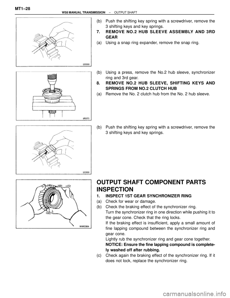
(b) Push the shifting key spring with a screwdriver, remove the
3 shifting keys and key springs.
7. REMOVE NO.2 HUB SLEEVE ASSEMBLY AND 3RD
GEAR
(a) Using a snap ring expander, remove the snap ring.
(b) Using a press, remove the No.2 hub sleeve, synchronizer
ring and 3rd gear.
8. REMOVE NO.2 HUB SLEEVE, SHIFTING KEYS AND
SPRINGS FROM NO.2 CLUTCH HUB
(a) Remove the No. 2 clutch hub from the No. 2 hub sleeve.
(b) Push the shifting key spring with a screwdriver, remove the
3 shifting keys and key springs.
OUTPUT SHAFT COMPONENT PARTS
INSPECTION
1. INSPECT 1ST GEAR SYNCHRONIZER RING
(a) Check for wear or damage.
(b) Check the braking effect of the synchronizer ring.
Turn the synchronizer ring in one direction while pushing it to
the gear cone. Check that the ring locks.
If the braking effect is insufficient, apply a small amount of
fine lapping compound between the synchronizer ring and
gear cone.
Lightly rub the synchronizer ring and gear cone together.
NOTICE: Ensure the fine lapping compound is complete-
ly washed off after rubbing.
(c) Check again the braking effect of the synchronizer ring. If it
does not lock, replace the synchronizer ring. MT1±28
± W58 MANUAL TRANSMISSIONOUTPUT SHAFT
Page 1297 of 2543
(e) Using a dial indicator, check the shaft runout.
Maximum runout:
0.06 mm (0.0024 in.)
If the runout exceeds the maximum, replace the output shaft.
OUTPUT SHAFT ASSEMBLY
HINT: Coat all of the sliding and rotating surface with gear oil
before assembly.
1. INSTALL NO.1 AND NO.2 CLUTCH HUB INTO HUB
SLEEVE
(a) Install the 3 shifting key springs to the clutch hub.
(b) While pushing the shifting key spring with a screw±driver,
install the 3 shifting keys.
(c) While pushing the 3 shifting keys, install the clutch hub to the
hub sleeve, as shown.
2. INSTALL 3RD GEAR AND NO.2 CLUTCH HUB ON
OUTPUT SHAFT
(a) Apply gear oil to the shaft.
(b) Place the synchronizer ring on the gear and align the ring
slots with the shifting keys.
± W58 MANUAL TRANSMISSIONOUTPUT SHAFTMT1±31
Page 1298 of 2543
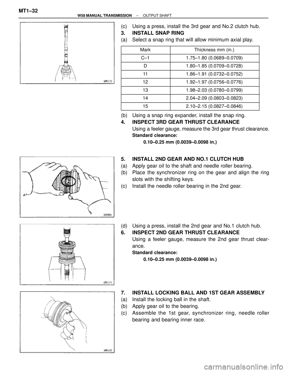
(c) Using a press, install the 3rd gear and No.2 clutch hub.
3. INSTALL SNAP RING
(a) Select a snap ring that will allow minimum axial play.
�������� ��������Mark������������� �������������Thickness mm (in.)
�������� ��������C±1������������� �������������1.75±1.80 (0.0689±0.0709)
�������� ��������D������������� �������������1.80±1.85 (0.0709±0.0728)
�������� ��������11������������� �������������1.86±1.91 (0.0732±0.0752)�������� ��������12������������� �������������1.92±1.97 (0.0756±0.0776)�������� �
������� ��������13
������������� �
������������ �������������1.98±2.03 (0.0780±0.0799)
�������� ��������14������������� �������������2.04±2.09 (0.0803±0.0823)
�������� ��������15������������� �������������2.10±2.15 (0.0827±0.0846)
(b) Using a snap ring expander, install the snap ring.
4. INSPECT 3RD GEAR THRUST CLEARANCE
Using a feeler gauge, measure the 3rd gear thrust clearance.
Standard clearance:
0.10±0.25 mm (0.0039±0.0098 in.)
5. INSTALL 2ND GEAR AND NO.1 CLUTCH HUB
(a) Apply gear oil to the shaft and needle roller bearing.
(b) Place the synchronizer ring on the gear and align the ring
slots with the shifting keys.
(c) Install the needle roller bearing in the 2nd gear.
(d) Using a press, install the 2nd gear and No.1 clutch hub.
6. INSPECT 2ND GEAR THRUST CLEARANCE
Using a feeler gauge, measure the 2nd gear thrust clear-
ance.
Standard clearance:
0.10±0.25 mm (0.0039±0.0098 in.)
7. INSTALL LOCKING BALL AND 1ST GEAR ASSEMBLY
(a) Install the locking ball in the shaft.
(b) Apply gear oil to the bearing.
(c) Assemble the 1st gear, synchronizer ring, needle roller
bearing and bearing inner race. MT1±32
± W58 MANUAL TRANSMISSIONOUTPUT SHAFT