Page 1179 of 2543
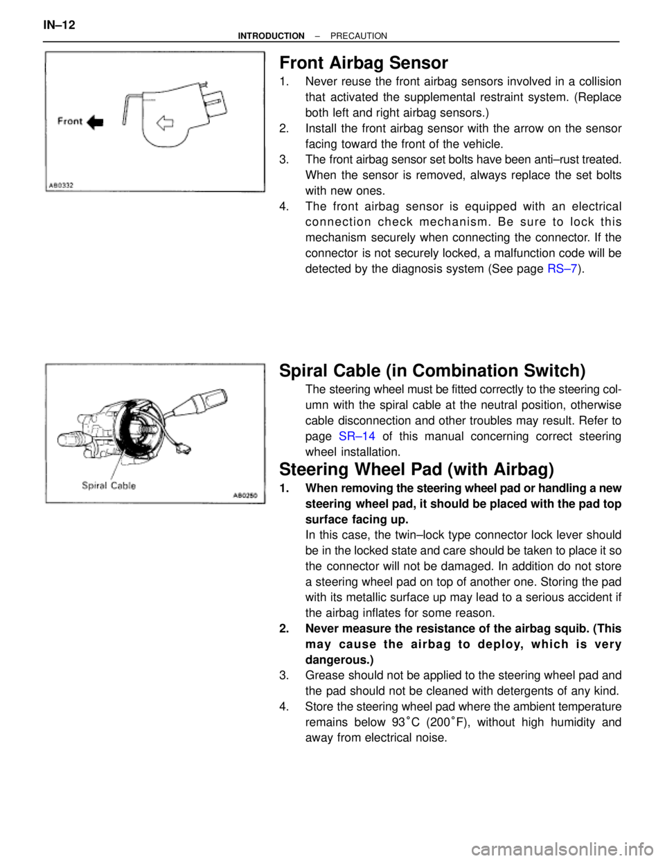
Front Airbag Sensor
1. Never reuse the front airbag sensors involved in a collision
that activated the supplemental restraint system. (Replace
both left and right airbag sensors.)
2. Install the front airbag sensor with the arrow on the sensor
facing toward the front of the vehicle.
3. The front airbag sensor set bolts have been anti±rust treated.
When the sensor is removed, always replace the set bolts
with new ones.
4. The front airbag sensor is equipped with an electrical
connection check mechanism. Be sure to lock this
mechanism securely when connecting the connector. If the
connector is not securely locked, a malfunction code will be
detected by the diagnosis system (See page RS±7).
Spiral Cable (in Combination Switch)
The steering wheel must be fitted correctly to the steering col-
umn with the spiral cable at the neutral position, otherwise
cable disconnection and other troubles may result. Refer to
page SR±14 of this manual concerning correct steering
wheel installation.
Steering Wheel Pad (with Airbag)
1. When removing the steering wheel pad or handling a new
steering wheel pad, it should be placed with the pad top
surface facing up.
In this case, the twin±lock type connector lock lever should
be in the locked state and care should be taken to place it so
the connector will not be damaged. In addition do not store
a steering wheel pad on top of another one. Storing the pad
with its metallic surface up may lead to a serious accident if
the airbag inflates for some reason.
2. Never measure the resistance of the airbag squib. (This
may cause the airbag to deploy, which is very
dangerous.)
3. Grease should not be applied to the steering wheel pad and
the pad should not be cleaned with detergents of any kind.
4. Store the steering wheel pad where the ambient temperature
remains below 93°C (200°F), without high humidity and
away from electrical noise. IN±12
± INTRODUCTIONPRECAUTION
Page 1249 of 2543
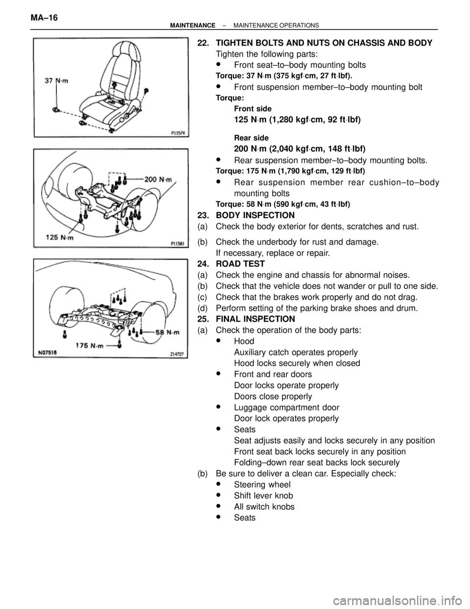
22. TIGHTEN BOLTS AND NUTS ON CHASSIS AND BODY
Tighten the following parts:
wFront seat±to±body mounting bolts
Torque: 37 NVm (375 kgfVcm, 27 ftVlbf).
wFront suspension member±to±body mounting bolt
Torque:
Front side
125 NVm (1,280 kgfVcm, 92 ftVlbf)
Rear side
200 NVm (2,040 kgfVcm, 148 ftVlbf)
wRear suspension member±to±body mounting bolts.
Torque: 175 NVm (1,790 kgfVcm, 129 ftVlbf)
wRear suspension member rear cushion±to±body
mounting bolts
Torque: 58 NVm (590 kgfVcm, 43 ftVlbf)
23. BODY INSPECTION
(a) Check the body exterior for dents, scratches and rust.
(b) Check the underbody for rust and damage.
If necessary, replace or repair.
24. ROAD TEST
(a) Check the engine and chassis for abnormal noises.
(b) Check that the vehicle does not wander or pull to one side.
(c) Check that the brakes work properly and do not drag.
(d) Perform setting of the parking brake shoes and drum.
25. FINAL INSPECTION
(a) Check the operation of the body parts:
wHood
Auxiliary catch operates properly
Hood locks securely when closed
wFront and rear doors
Door locks operate properly
Doors close properly
wLuggage compartment door
Door lock operates properly
wSeats
Seat adjusts easily and locks securely in any position
Front seat back locks securely in any position
Folding±down rear seat backs lock securely
(b) Be sure to deliver a clean car. Especially check:
wSteering wheel
wShift lever knob
wAll switch knobs
wSeats MA±16
± MAINTENANCEMAINTENANCE OPERATIONS
Page 1260 of 2543
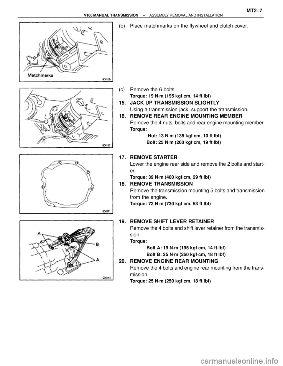
(b) Place matchmarks on the flywheel and clutch cover.
(c) Remove the 6 bolts.
Torque: 19 NVm (195 kgfVcm, 14 ftVlbf)
15. JACK UP TRANSMISSION SLIGHTLY
Using a transmission jack, support the transmission.
16. REMOVE REAR ENGINE MOUNTING MEMBER
Remove the 4 nuts, bolts and rear engine mounting member.
Torque:
VNut: 13 NVm (135 kgfVcm, 10 ftVlbf)
Bolt: 25 NVm (260 kgfVcm, 19 ftVlbf)
17. REMOVE STARTER
Lower the engine rear side and remove the 2 bolts and start-
er.
Torque: 39 NVm (400 kgfVcm, 29 ftVlbf)
18. REMOVE TRANSMISSION
Remove the transmission mounting 5 bolts and transmission
from the engine.
Torque: 72 NVm (730 kgfVcm, 53 ftVlbf)
19. REMOVE SHIFT LEVER RETAINER
Remove the 4 bolts and shift lever retainer from the transmis-
sion.
Torque:
Bolt A: 19 NVm (195 kgfVcm, 14 ftVlbf)
Bolt B: 25 NVm (250 kgfVcm, 18 ftVlbf)
20. REMOVE ENGINE REAR MOUNTING
Remove the 4 bolts and engine rear mounting from the trans-
mission.
Torque: 25 NVm (250 kgfVcm, 18 ftVlbf)
± V160 MANUAL TRANSMISSIONASSEMBLY REMOVAL AND INSTALLATIONMT2±7
Page 1409 of 2543
6. 2JZ±GTE M/T:
REMOVE CLUTCH COVER SET BOLTS
(a) Remove the 2 bolts and service hole cover.
(b) Place the matchmarks on the flywheel and clutch cover.
(c) Remove the 6 bolts.
7. A/T:
REMOVE TORQUE CONVERTER CLUTCH MOUNTING
BOLTS
(a) Remove the hole plug.
(b) Turn the crankshaft to gain access to each bolt.
Remove the 6 bolts.
8. SEPARATE ENGINE AND TRANSMISSION
Remove the 6 bolts and transmission.
HINT: The º17º is 17 mm head bolt, and º14º is 14 mm head
bolt.
9. 2JZ±GE M/T:
REMOVE CLUTCH COVER AND DISC
(a) Place matchmarks on the flywheel and clutch cover.
(b) Loosen each bolt one turn at a time until spring tension is
released.
(c) Remove the bolts, and pull off the clutch cover with the clutch
disc.
NOTICE: Do not drop the clutch disc.
± ENGINEENGINE MECHANICALEG±95
Page 1412 of 2543
PREPARATION FOR DISASSEMBLY
1. M/T:
REMOVE FLYWHEEL
2. A/T:
REMOVE DRIVE PLATE
3. INSTALL ENGINE TO ENGINE STAND FOR
DISASSEMBLY
4. REMOVE GENERATOR
5. REMOVE TIMING BELT AND PULLEYS
(See timing belt removal)
6. REMOVE CYLINDER HEAD
(See cylinder head removal)
7. REMOVE OIL FILTER
(See oil and filter replacement in Lubrication System)
8. 2JZ±GTE:
REMOVE OIL COOLER
(See oil cooler removal in Lubrication System)
9. REMOVE NO.2 WATER BYPASS PIPE
(a) 2JZ±GE:
Remove the bolt, 2 nuts, water bypass pipe and gasket.
(b) 2JZ±GTE:
Remove the 2 bolts, 2 nuts, water bypass pipe and gasket.
10. REMOVE OIL FILTER BRACKET
Remove the union bolt, gasket, oil filter bracket and O ±ring.
11. REMOVE LH ENGINE MOUNTING BRACKET AND
INSULATOR ASSEMBLY
12. REMOVE FUEL PIPE SUPPORT EG±98
± ENGINEENGINE MECHANICAL
Page 1436 of 2543
8. INSTALL FUEL PIPE SUPPORT
Torque: 14 NVm (145 kgfVcm, 10 ftVlbf)
9. INSTALL LH ENGINE MOUNTING BRACKET AND
INSULATOR ASSEMBLY
HINT: LH mounting bracket is marked ºA u INº.
Torque: 58 NVm (590 kgfVcm, 43 ftVlbf)
10. INSTALL OIL FILTER BRACKET
(a) Check and clean the oil filter bracket installation.
(b) Place a new O±ring in position on the oil filter bracket.
(c) Apply clean engine oil to the O±ring.
(d) Install a new gasket to the union bolt.
(e) Install the oil filter braket with the union bolt.
Torque: 88 NVm (900 kgfVcm, 65 ftVlbf)
11. INSTALL NO.2 WATER BYPASS PIPE
(a) Install a new gasket to the water pump.
(b) 2JZ±GE:
Install the water bypass pipe with the bolt and 2 nuts.
Torque: 21 NVm (210 kgfVcm, 15 ftVlbf)
(c) 2JZ±GTE:
Install the water bypass pipe with the 2 bolts and 2 nuts.
Torque: 21 NVm (210 kgfVcm, 15 ftVlbf)
12. 2JZ±GTE:
INSTALL OIL COOLER
(See oil cooler installation in Lubrication System)
13. INSTALL OIL FILTER
(See oil and filter replacement in Lubrication System)
14. INSTALL CYLINDER HEAD
(See cylinder head installation)
15. INSTALL TIMING PULLEYS AND BELT
(See timing belt installation)
16. INSTALL GENERATOR
(See generator installation in Charging System)
17. REMOVE ENGINE STAND FROM ENGINE
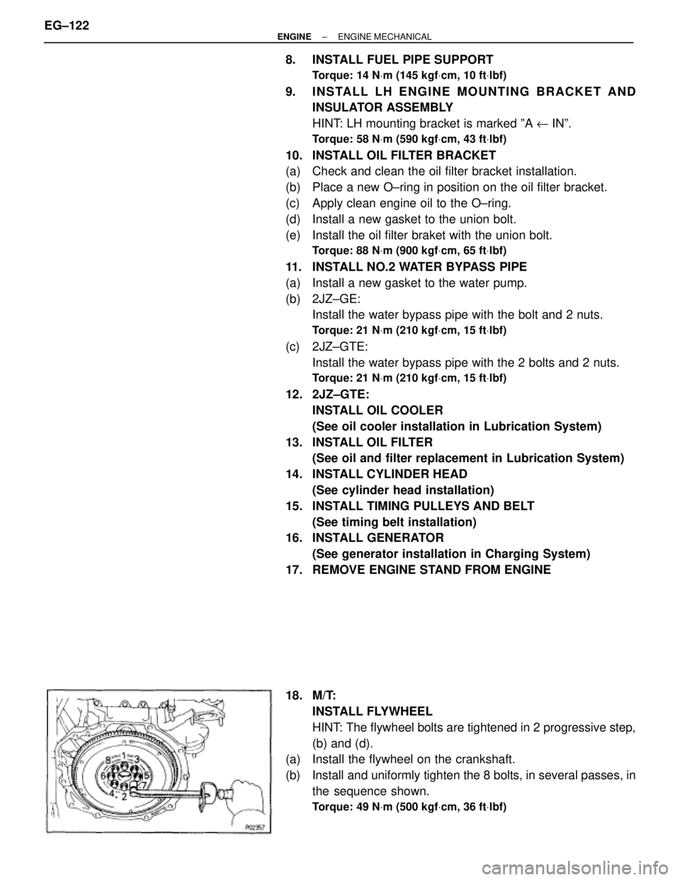
18. M/T:
INSTALL FLYWHEEL
HINT: The flywheel bolts are tightened in 2 progressive step,
(b) and (d).
(a) Install the flywheel on the crankshaft.
(b) Install and uniformly tighten the 8 bolts, in several passes, in
the sequence shown.
Torque: 49 NVm (500 kgfVcm, 36 ftVlbf)
EG±122± ENGINEENGINE MECHANICAL
Page 1437 of 2543
(c) Mark the flywheel bolt with paint.
(d) Retighten the flywheel bolts by an additional 90°.
(e) Check that the painted mark is now at a 90° angle to (d).
19. A/T:
INSTALL DRIVE PLATE
(a) Install the front spacer, drive plate and rear plate on the
crankshaft.
Adhesive:
Part No. 08833±00070, THREE BOND 1324 or equivalent
(b) Apply adhesive to 2 or 3 threads of the mounting bolt end.
(c) Install and uniformly tighten the 8 bolts, in several passes, in
the sequence shown.
Torque: 83 NVm (850 kgfVcm, 61 ftVlbf)
± ENGINEENGINE MECHANICALEG±123
Page 1438 of 2543
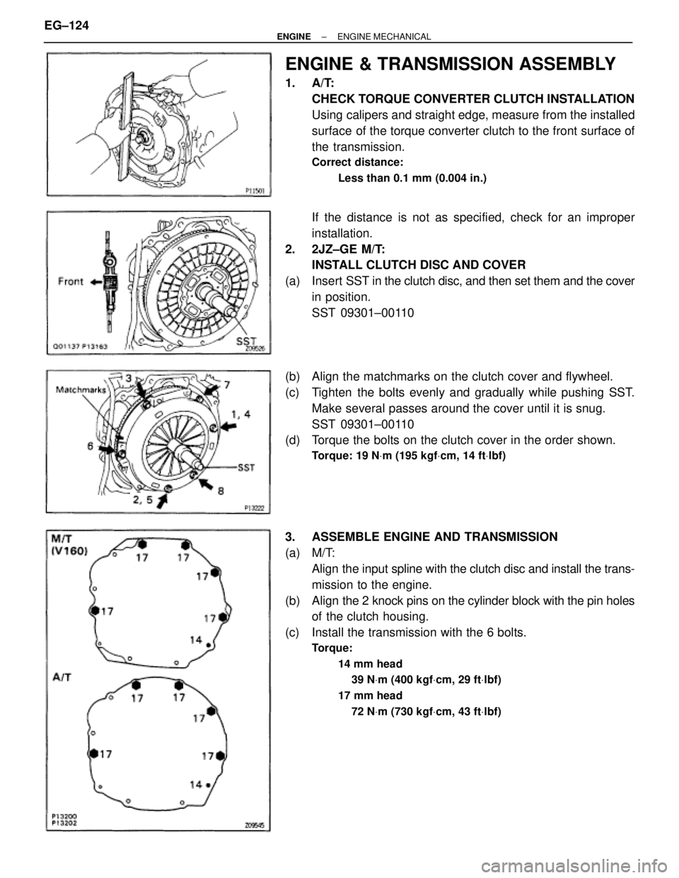
ENGINE & TRANSMISSION ASSEMBLY
1. A/T:
CHECK TORQUE CONVERTER CLUTCH INSTALLATION
Using calipers and straight edge, measure from the installed
surface of the torque converter clutch to the front surface of
the transmission.
Correct distance:
Less than 0.1 mm (0.004 in.)
If the distance is not as specified, check for an improper
installation.
2. 2JZ±GE M/T:
INSTALL CLUTCH DISC AND COVER
(a) Insert SST in the clutch disc, and then set them and the cover
in position.
SST 09301±00110
(b) Align the matchmarks on the clutch cover and flywheel.
(c) Tighten the bolts evenly and gradually while pushing SST.
Make several passes around the cover until it is snug.
SST 09301±00110
(d) Torque the bolts on the clutch cover in the order shown.
Torque: 19 NVm (195 kgfVcm, 14 ftVlbf)
3. ASSEMBLE ENGINE AND TRANSMISSION
(a) M/T:
Align the input spline with the clutch disc and install the trans-
mission to the engine.
(b) Align the 2 knock pins on the cylinder block with the pin holes
of the clutch housing.
(c) Install the transmission with the 6 bolts.
Torque:
14 mm head
39 NVm (400 kgfVcm, 29 ftVlbf)
17 mm head
72 NVm (730 kgfVcm, 43 ftVlbf)
EG±124± ENGINEENGINE MECHANICAL