Page 29 of 2543

INSPECTION PROCEDURE
Proceed to next circuit inspection shown on matrix
chart (See page AC±26). However, if the light is still
blinking, check and replace A/C amplifier.
(See page IN±30).(See Page IN±30).
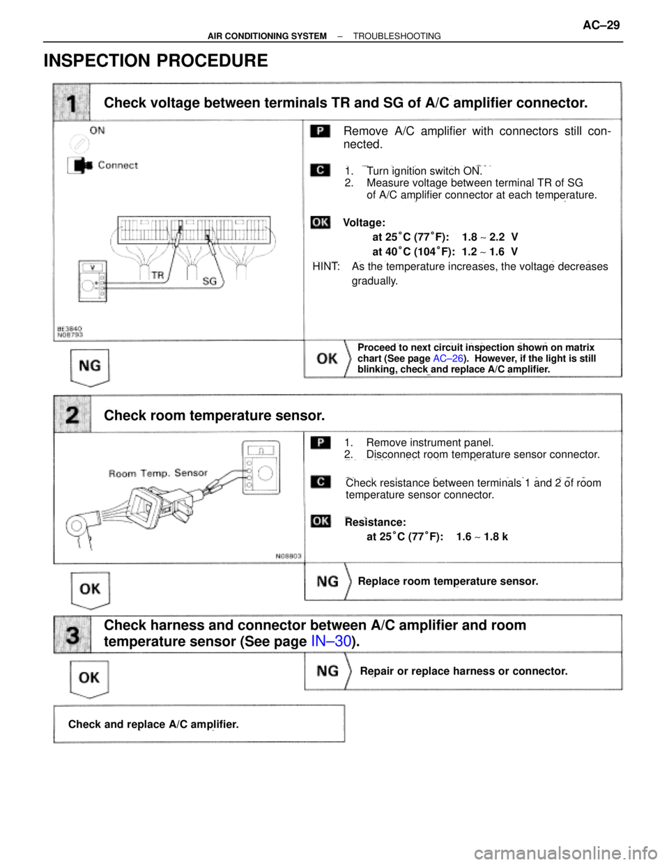
Remove A/C amplifier with connectors still con-
nected.
Check voltage between terminals TR and SG of A/C amplifier connector.
Check room temperature sensor.
Check harness and connector between A/C amplifier and room
temperature sensor (See page
IN±30).
Replace room temperature sensor.
Repair or replace harness or connector.
Check and replace A/C amplifier.
1. Turn ignition switch ON.
2. Measure voltage between terminal TR of SG
of A/C amplifier connector at each temperature.
1. Remove instrument panel.
2. Disconnect room temperature sensor connector.
Check resistance between terminals 1 and 2 of room
temperature sensor connector.
Resistance:
at 25°C (77°F): 1.6 ~ 1.8 k�
HINT: As the temperature increases, the voltage decreases
gradually.
Voltage:
at 25°C (77°F): 1.8 ~ 2.2 V
at 40°C (104°F): 1.2 ~ 1.6 V
± AIR CONDITIONING SYSTEMTROUBLESHOOTINGAC±29
Page 30 of 2543
CIRCUIT DESCRIPTION
This sensor detects the ambient temperature and sends the appropriate signals to the A/C amplifier.
Diagnostic Sensor Check Detecting Condition
Open or short in ambient temperature sensor circuit.
Trouble Area
�Ambient temperature sensor
�Harness or connector between ambient tempera±
ture sensor and A/C amplifier
�A/C amplifier
Blinking Light B L Ambient Temperature Sensor Circuit
AC±30± AIR CONDITIONING SYSTEMTROUBLESHOOTING
Page 31 of 2543

(See page AC±26)
(See page IN±30).
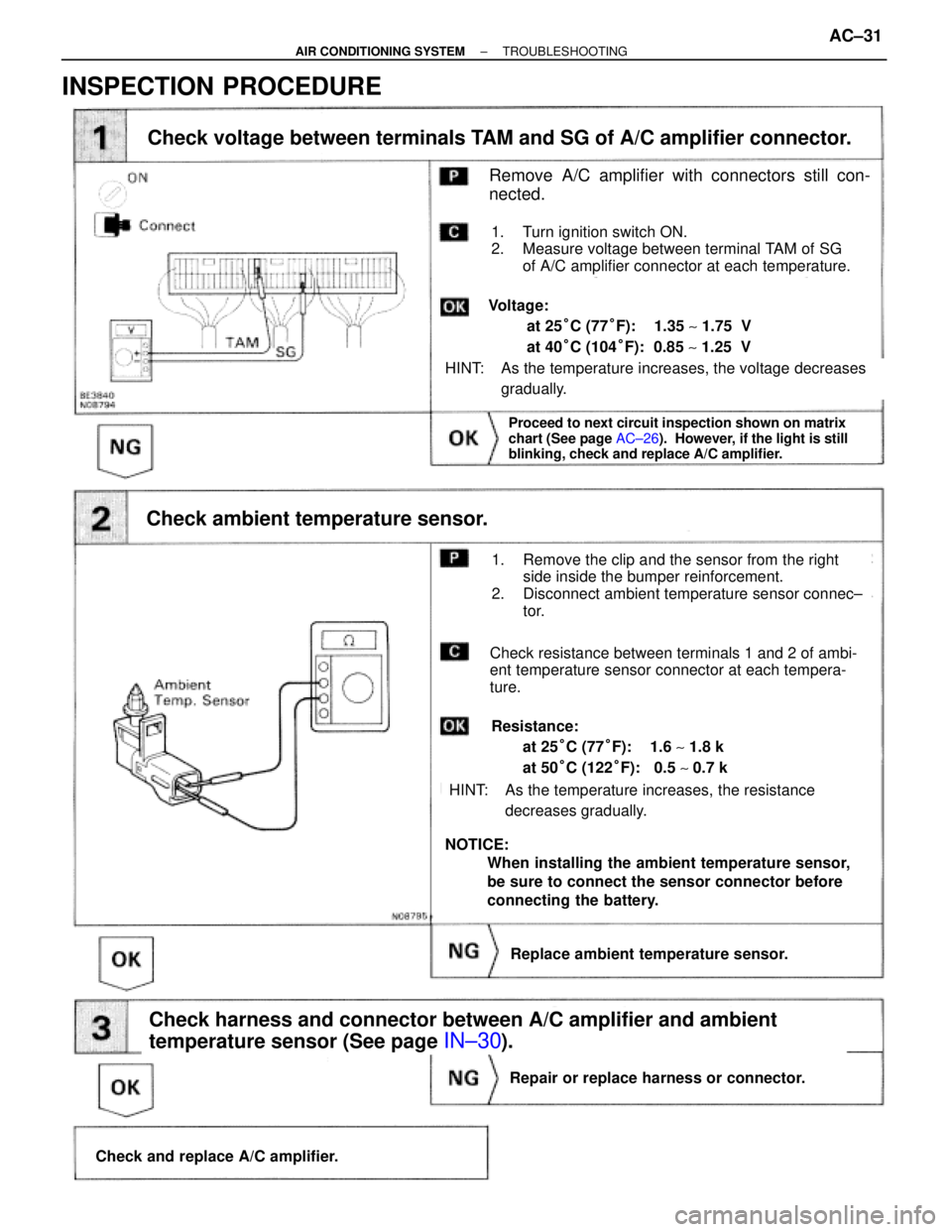
Check voltage between terminals TAM and SG of A/C amplifier connector.
Check ambient temperature sensor.
Check harness and connector between A/C amplifier and ambient
temperature sensor (See page
IN±30).
Proceed to next circuit inspection shown on matrix
chart (See page AC±26). However, if the light is still
blinking, check and replace A/C amplifier.
Check and replace A/C amplifier.
Repair or replace harness or connector.
Replace ambient temperature sensor.
Remove A/C amplifier with connectors still con-
nected.
1. Turn ignition switch ON.
2. Measure voltage between terminal TAM of SG
of A/C amplifier connector at each temperature.
HINT: As the temperature increases, the voltage decreases
gradually.
Voltage:
at 25°C (77°F): 1.35 ~ 1.75 V
at 40°C (104°F): 0.85 ~ 1.25 V
1. Remove the clip and the sensor from the right
side inside the bumper reinforcement.
2. Disconnect ambient temperature sensor connec±
tor.
Check resistance between terminals 1 and 2 of ambi-
ent temperature sensor connector at each tempera-
ture.
Resistance:
at 25°C (77°F): 1.6 ~ 1.8 k�
at 50°C (122°F): 0.5 ~ 0.7 k�
HINT: As the temperature increases, the resistance
decreases gradually.
NOTICE:
When installing the ambient temperature sensor,
be sure to connect the sensor connector before
connecting the battery.
INSPECTION PROCEDURE
± AIR CONDITIONING SYSTEMTROUBLESHOOTINGAC±31
Page 32 of 2543
Blinking Light FOOT Evaporator Temperature Sensor Circuit
CIRCUIT DESCRIPTION
This sensor detects the temperature inside the cooling unit and sends the appropriate signals to the
A/C amplifier.
Diagnostic Sensor Check Detecting ConditionTrouble Area
Open or short in evaporator temperature sensor
circuit.�Evaporator temperature sensor
�Harness or connector between evaporator
temperature sensor and A/C amplifier
�A/C amplifier
AC±32± AIR CONDITIONING SYSTEMTROUBLESHOOTING
Page 33 of 2543

INSPECTION PROCEDURE
(See page AC±26).
(See page IN±30)
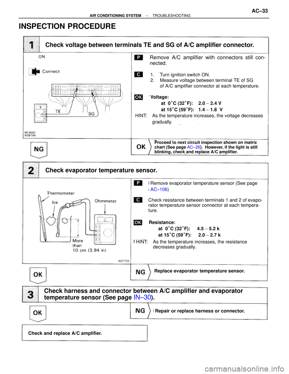
Check voltage between terminals TE and SG of A/C amplifier connector.
Check and replace A/C amplifier.
Repair or replace harness or connector.
Replace evaporator temperature sensor.
Check harness and connector between A/C amplifier and evaporator
temperature sensor (See page
IN±30).
Proceed to next circuit inspection shown on matrix
chart (See page AC±26). However, if the light is still
blinking, check and replace A/C amplifier.
Check evaporator temperature sensor.
Remove A/C amplifier with connectors still con-
nected.
1. Turn ignition switch ON.
2. Measure voltage between terminal TE of SG
of A/C amplifier connector at each temperature.
HINT: As the temperature increases, the voltage decreases
gradually.
Voltage:
at 0°C (32°F): 2.0 ~ 2.4 V
at 15°C (59°F): 1.4 ~ 1.8 V
Check resistance between terminals 1 and 2 of evapo-
rator temperature sensor connector at each tempera-
ture.
Resistance:
at 0°C (32°F): 4.5 ~ 5.2 k�
at 15°C (59°F): 2.0 ~ 2.7 k�
HINT: As the temperature increases, the resistance
decreases gradually.
Remove evaporator temperature sensor (See page
AC±106)
± AIR CONDITIONING SYSTEMTROUBLESHOOTINGAC±33
Page 34 of 2543
Blinking Light F D Engine Coolant Temperature Sensor Circuit
CIRCUIT DESCRIPTION
This sensor detects the coolant temperature and sends the appropriate signals to the A/C amplifier.
These signals are used for warm up control when the engine is cold.
Diagnostic Sensor Check Detecting ConditionTrouble Area
Open or short in engine coolant temperature sensor
circuit.�Engine coolant temperature sensor
�Harness or connector between engine coolant
temperature sensor and A/C amplifier
�A/C amplifier
AC±34± AIR CONDITIONING SYSTEMTROUBLESHOOTING
Page 35 of 2543

INSPECTION PROCEDURE
(See page AC±26).
(See page IN±30)
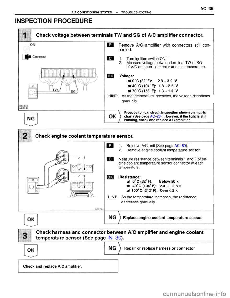
Check voltage between terminals TW and SG of A/C amplifier connector.
Proceed to next circuit inspection shown on matrix
chart (See page AC±26). However, if the light is still
blinking, check and replace A/C amplifier.
Check engine coolant temperature sensor.
Replace engine coolant temperature sensor.
Check harness and connector between A/C amplifier and engine coolant
temperature sensor (See page
IN±30).
Repair or replace harness or connector.
Check and replace A/C amplifier.
Remove A/C amplifier with connectors still con-
nected.
1. Turn ignition switch ON.
2. Measure voltage between terminal TW of SG
of A/C amplifier connector at each temperature.
HINT: As the temperature increases, the voltage decreases
gradually.
Voltage:
at 0°C (32°F): 2.8 ~ 3.2 V
at 40°C (104°F): 1.8 ~ 2.2 V
at 70°C (158°F): 1.3 ~ 1.5 V
1. Remove A/C unit (See page AC±80).
2. Remove engine coolant temperature sensor.
Measure resistance between terminals 1 and 2 of en-
gine coolant temperature sensor connector at each
temperature.
HINT: As the temperature increases, the resistance
decreases gradually.
Resistance:
at 0°C (32°F): Below 50 k�
at 40°C (104°F): 2.4 ~ 2.8 k�
at 100°C (212°F): Over 0.2 k�
± AIR CONDITIONING SYSTEMTROUBLESHOOTINGAC±35
Page 36 of 2543
Blinking Light DEF Solar Sensor Circuit
CIRCUIT DESCRIPTION
A photo diode in the solar sensor detects solar radi±
ation and sends signals to the A/C amplifier.
Diagnostic Sensor Check Detecting ConditionTrouble Area
�Solar sensor
�Harness or connector between solar sensor and
A/C amplifier
�A/C amplifierOpen or short in solar sensor circuit.
Please not that blinking of the LED for DEF is not
abnormal when the sensor is not receiving solar
radiation.
AC±36± AIR CONDITIONING SYSTEMTROUBLESHOOTING