Page 46 of 2543
Air Inlet Damper Control Servo Motor Circuit
CIRCUIT DESCRIPTION
The air inlet damper control servo motor is controlled by the A/C amplifier and signals the air inlet damper
to move to the desired position.
ConditionTrouble Area
�Air inlet damper position sensor
�Harness or connector between air inlet damper
control servo motor assembly and A/C amplifier
�A/C amplifierAir mix damper position sensor value does not
change even if A/C amplifier signals the air mix
damper control servo motor to operate.
AC±46± AIR CONDITIONING SYSTEMTROUBLESHOOTING
Page 48 of 2543
Blinking Light LO HI Air Outlet Damper Position Sensor Circuit
CIRCUIT DESCRIPTION
This sensor detects the position of the air mix
damper and sends the appropriate signals to the
A/C amplifier.
The position sensor is built into the air outlet
damper control servo motor assembly.
Trouble AreaDiagnostic Sensor Check Detecting ConditionLight
LO
HI
Short to ground or power source circuit in air
outlet damper position sensor circuit.
Air outlet damper position sensor value does
not change even if A/C amplifier signals the air
outlet damper control servo motor to move.
�Air outlet damper position sensor
�Harness or connector between air outlet
damper control servo motor assembly and
A/C amplifier
�A/C amplifier
AC±48± AIR CONDITIONING SYSTEMTROUBLESHOOTING
Page 49 of 2543

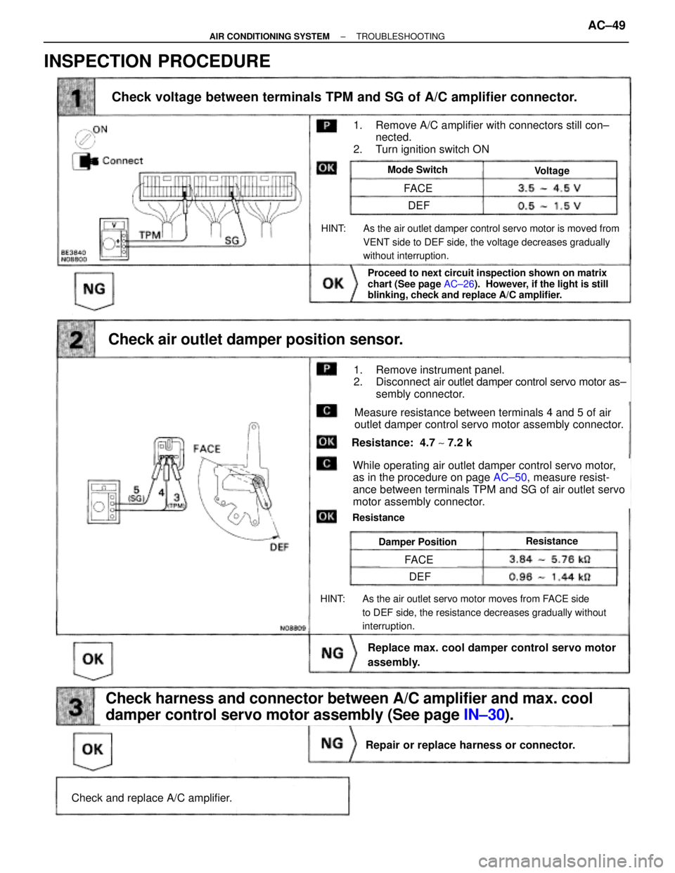
(See page IN±30).
AC±50,
Check voltage between terminals TPM and SG of A/C amplifier connector.
Check and replace A/C amplifier.
Repair or replace harness or connector.
Check harness and connector between A/C amplifier and max. cool
damper control servo motor assembly (See page IN±30).
Replace max. cool damper control servo motor
assembly.
Check air outlet damper position sensor.
Proceed to next circuit inspection shown on matrix
chart (See page AC±26). However, if the light is still
blinking, check and replace A/C amplifier.
ResistanceDamper Position
Resistance: 4.7 ~ 7.2 k�
While operating air outlet damper control servo motor,
as in the procedure on page AC±50, measure resist-
ance between terminals TPM and SG of air outlet servo
motor assembly connector.
Resistance
HINT: As the air outlet servo motor moves from FACE side
to DEF side, the resistance decreases gradually without
interruption.
Measure resistance between terminals 4 and 5 of air
outlet damper control servo motor assembly connector.
1. Remove instrument panel.
2. Disconnect air outlet damper control servo motor as±
sembly connector.
HINT: As the air outlet damper control servo motor is moved from
VENT side to DEF side, the voltage decreases gradually
without interruption.
Mode SwitchVoltage
1. Remove A/C amplifier with connectors still con±
nected.
2. Turn ignition switch ON
FACE
FACE
DEF
DEF
INSPECTION PROCEDURE
± AIR CONDITIONING SYSTEMTROUBLESHOOTINGAC±49
Page 50 of 2543
Blinking Light HI Air Outlet Damper Control Servo Motor Circuit
CIRCUIT DESCRIPTION
This circuit turns the servo motor and changes each mode damper position by the signals from the A/C
amplifier. When the AUTO switch is on, the A/C amplifier changes the mode automatically between
(FACE), (BI±LEVEL) and (FOOT) according to the temperature setting.
Trouble AreaDiagnostic Sensor Check Detecting Condition
�Air outlet damper control servo motor
�Air outlet damper position sensor
�Harness or connector between A/C amplifier and
air outlet damper control servo motor, air outlet
damper position sensor
�A/C amplifier Air outlet damper position sensor value does not
change even if A/C amplifier signals the air outlet
damper control servo motor.
AC±50± AIR CONDITIONING SYSTEMTROUBLESHOOTING
Page 52 of 2543
Back Up Power Source Circuit
CIRCUIT DESCRIPTION
This is the back up power source for the A/C amplifier. Power is supplied even when the ignition switch is off
and is used for diagnostic sensor check memory, etc.
AC±52± AIR CONDITIONING SYSTEMTROUBLESHOOTING
Page 66 of 2543
A C Control Assembly Circuit
CIRCUIT DESCRIPTION
This circuit includes the control switch circuit and the LED circuit in the A/C control Assembly.
The A/C amplifier always searches which switch is operated and drives the LED according to A/C control opera-
tion or diagnostic sensor check operation.
AC±66± AIR CONDITIONING SYSTEMTROUBLESHOOTING
Page 83 of 2543

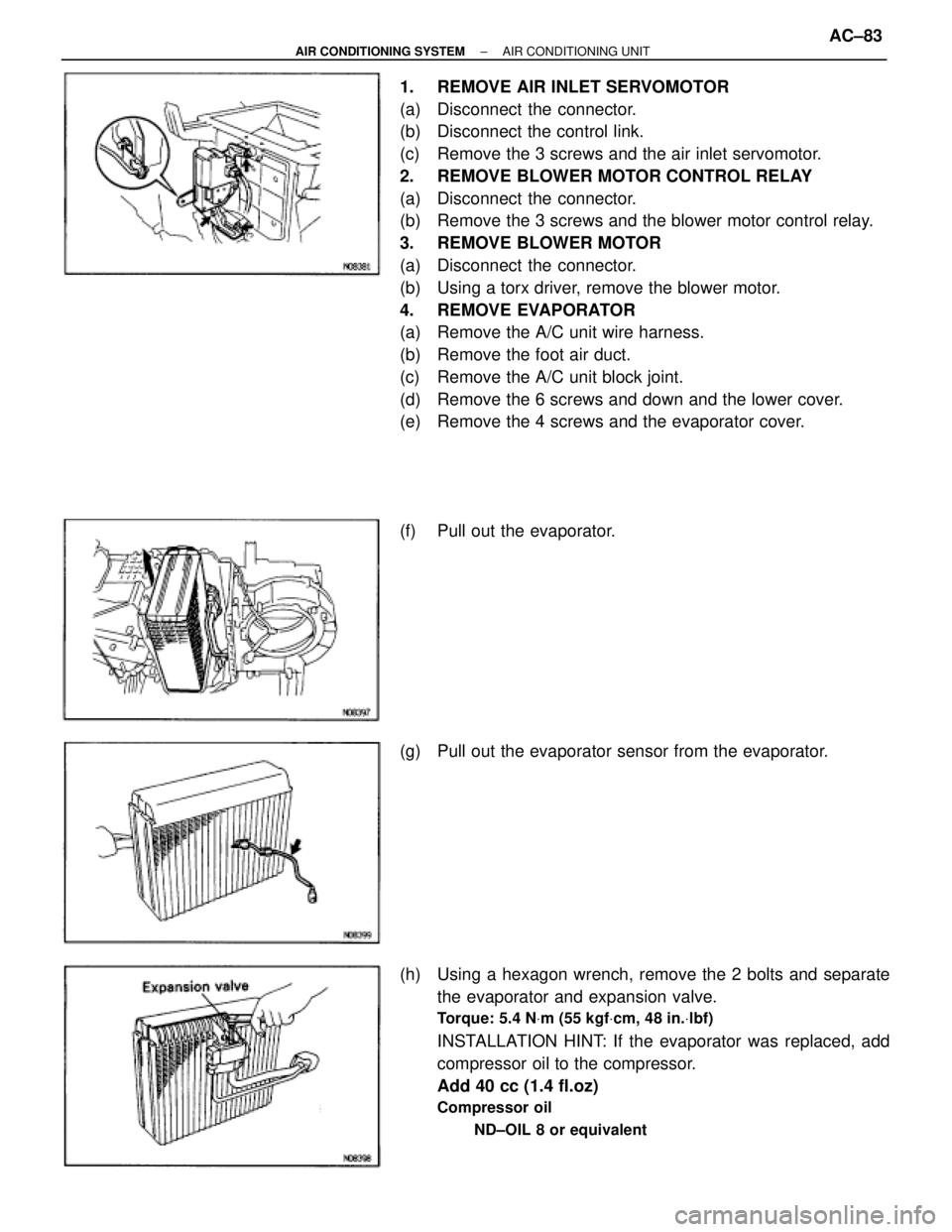
1. REMOVE AIR INLET SERVOMOTOR
(a) Disconnect the connector.
(b) Disconnect the control link.
(c) Remove the 3 screws and the air inlet servomotor.
2. REMOVE BLOWER MOTOR CONTROL RELAY
(a) Disconnect the connector.
(b) Remove the 3 screws and the blower motor control relay.
3. REMOVE BLOWER MOTOR
(a) Disconnect the connector.
(b) Using a torx driver, remove the blower motor.
4. REMOVE EVAPORATOR
(a) Remove the A/C unit wire harness.
(b) Remove the foot air duct.
(c) Remove the A/C unit block joint.
(d) Remove the 6 screws and down and the lower cover.
(e) Remove the 4 screws and the evaporator cover.
(f) Pull out the evaporator.
(g) Pull out the evaporator sensor from the evaporator.
(h) Using a hexagon wrench, remove the 2 bolts and separate
the evaporator and expansion valve.
Torque: 5.4 NVm (55 kgfVcm, 48 in.Vlbf)
INSTALLATION HINT: If the evaporator was replaced, add
compressor oil to the compressor.
Add 40 cc (1.4 fl.oz)
Compressor oil
ND±OIL 8 or equivalent
± AIR CONDITIONING SYSTEMAIR CONDITIONING UNITAC±83
Page 84 of 2543
5. REMOVE AIR MIX SERVOMOTO
(a) Remove the defroster duct.
(b) Remove the 3 screws and the water valve cover.
(c) Disconnect the connector.
(d) Disconnect the control link.
(e) Remove the 2 screws and the air mix servomotor.
6. REMOVE HEATER RADIATOR AND WATER VALVE
(a) Remove the 2 screws and the plate.
(b) Remove the 2 screws and the clamp.
(c) Remove the 3 screws.
(d) Pull out the heater radiator with the water valve.
(e) Remove the 2 screws and water valve from the heater
radiator.
7. REMOVE HEATER AIR DUCT
Remove the 2 screws and the defroster air duct.
8. REMOVE VENT AIR DUCT
(a) Disconnect the control link.
(b) Remove the 2 screws and the vent air duct.
9. REMOVE ENGINE COOLANT TEMPERATURE SENSOR
(a) Disconnect the connector.
(b) After pulling off the clamp, pull out the sensor.
10. REMOVE AIR OUTLET SERVOMOTOR
(a) Disconnect the connector.
(b) Remove the 3 screws and the air outlet servomotor. AC±84
± AIR CONDITIONING SYSTEMAIR CONDITIONING UNIT