Page 155 of 2543

A340E (2JZ-GTE) AUTOMATIC TRANSMISSIONOPERATION -
AT-7
3. HYDRAULIC CONTROL SYSTEM
The hydraulic control system is composed of the oil pump, the valve body, the solenoid valves, the accu-
mulators, the clutches and brakes, as well as the fluid passages which connect all of these components.
Based on the hydraulic pressure created by the oil pump, the hydraulic control system governs the hy-
draulic pressure acting on the torque converter clutch, clutches and brakes in accordance with the ve-
hicle driving conditions.
There are 5 solenoid valves on the valve body.
The No.1 and No.2 solenoid valves are turned on and off by signals from the ECM to control the shift
valves, and change the gear shift position.
The No.3 solenoid valve is operated by signals from the ECM to engage or disengage the lock-up
clutch of the torque converter clutch.
The No.4 solenoid valve is operated by signals from the ECM to control the engagement speed and
reduce gear shift shock.
The No.5 solenoid valve is operated by signals from the ECM to regulate the line pressure to throttle
pressure.
Page 225 of 2543
A340E (2JZ-GTE) AUTOMATIC TRANSMISSIONVALVE BODY -
AT-77
3. REMOVE 4 SOLENOIDS
(a) Remove No.1 and No.2 solenoids.
(b) Remove the O-ring from No.1 and No.2 solenoids.
(c) Remove the lock plate and No.3 and No.4 solenoids.
4. REMOVE OIL STRAINER AND PRESSURE RELIEF
VA LV E
5. TURN OVER ASSEMBLY AND REMOVE NO.5 SOLE-
NOID VALVE
6. REMOVE 28 BOLTS
7. LIFT OFF UPPER VALVE BODY AND PLATE
Page 233 of 2543
A340E (2JZ-GTE) AUTOMATIC TRANSMISSIONLOWER VALVE BODY -
AT-85
VALVE BODY ASSEMBLY
1. INSTALL ASSEMBLED GASKETS ON UPPER VALVE
BODY
Align the assembled gaskets with each bolt hole and
install the screw.
2. PLACE UPPER VALVE BODY WITH GASKETS ON
TOP OF LOWER VALVE BODY
Align each bolt hole and gaskets in the valve body.
3. INSTALL 28 BOLTS TO UPPER VALVE BODY
HINT: Each bolt length (mm, in.) is indicated below.
Torque: 6.5 N´m (65 kgf´cm, 56 in.´lbf)
Bolt length:
Bolt A: 45 mm (1.772 in.)
Bolt B: 35 mm (1.378 in.)
Bolt C: 20 mm (0.787 in.)
4. INSTALL NO.5 SOLENOID VALVE
5. TURN OVER ASSEMBLY INSTALL OIL STRAINER
AND PRESSURE RELIEF VALVE
AT0PV-02
Page 265 of 2543

A340E(Others) AUTOMATIC TRANSMISSIONOPERATION -
AT-8
3. HYDRAULIC CONTROL SYSTEM
The hydraulic control system is composed of the oil pump, the valve body, the solenoid valves, and the
clutches and brakes, as well as the fluid passages which connect all of these components. Based on
the hydraulic pressure created by the oil pump, the hydraulic control system governs the hydraulic pres-
sure acting on the torque converter clutch, clutches and brakes in accordance with the vehicle driving
conditions.
There are 3 solenoid valves on the valve body.
The No.1 and No.2 solenoid valves are turned on and off by signals from the ECM to operate the shift
valves and change the gear shift position.
The lock-up solenoid valve is operated by signals from the ECM to engage or disengage the lock-up
clutch of the torque converter clutch.
�LINE PRESSURE
Line pressure is the most basic and important pressure used in the automatic transmission, because
it is used to operate all of the clutches and brakes in the transmission.
If the primary regulator valve does not operate correctly, line pressure will be either too high or too low.
Line pressure that is too high will lead to shifting shock and consequent engine power loss due to the
greater effort required of the oil pump; line pressure that is too low will cause slippage of clutches and
brakes, which will, in extreme cases, prevent the vehicle from moving. Therefore, if either of these prob-
lems are noted, the line pressure should be measured to see if it is within specification.
�THROTTLE PRESSURE
Throttle pressure is always kept in accordance with the opening angle of the engine throttle valve. This
throttle pressure acts on the primary regulator valve and, the line pressure is regulated according to
the throttle valve opening.
In the hydraulically controlled automatic transmission, throttle pressure is used for regulating line pres-
sure and as signal pressure for up-shift and down-shift of the transmission. In the electronically con-
trolled transmission, however, throttle pressure is used only for regulating line pressure. Consequently,
improper adjustment of the transmission throttle cable may result in a line pressure that is too high or
too low. This, in turn, will lead to shifting shock or clutch and brake slippage.
Page 356 of 2543
A340E(Others) AUTOMATIC TRANSMISSIONLOWER VALVE BODY - A340E(Others) AUTOMATIC TRANSMISSIONLOWER VALVE BODY -
AT-99
VALVE BODY SPRING SPECIFICATIONS
HINT: During reassembly please refer to the spring specifications below to help you to identify the differ-
ent springs.
MarkName (Color)Free length / Outer diameter
mm (in.)Total No. of coils
(A)Check valve (None)20.2 (0.796) / 12.1 (0.476)6.5
(B)Pressure relief valve (None)11.2 (0.441) / 6.4 (0.252)7.5
(C)1-2 shift valve (Purple)30.8 (1.213) / 9.7 (0.382)10.5
(D)Primary regulator valve (Purple)62.3 (2.453) / 18.6 (0.732)12.5
(E)SUPRA
Accumulator control valve (White)36.1 (1.421) / 8.9 (0.327)14.0
(E)OTHERS
Accumulator control valve (Pink)33.9 (1.335) / 8.8 (0.346)12.0
AT06G-04
Page 392 of 2543

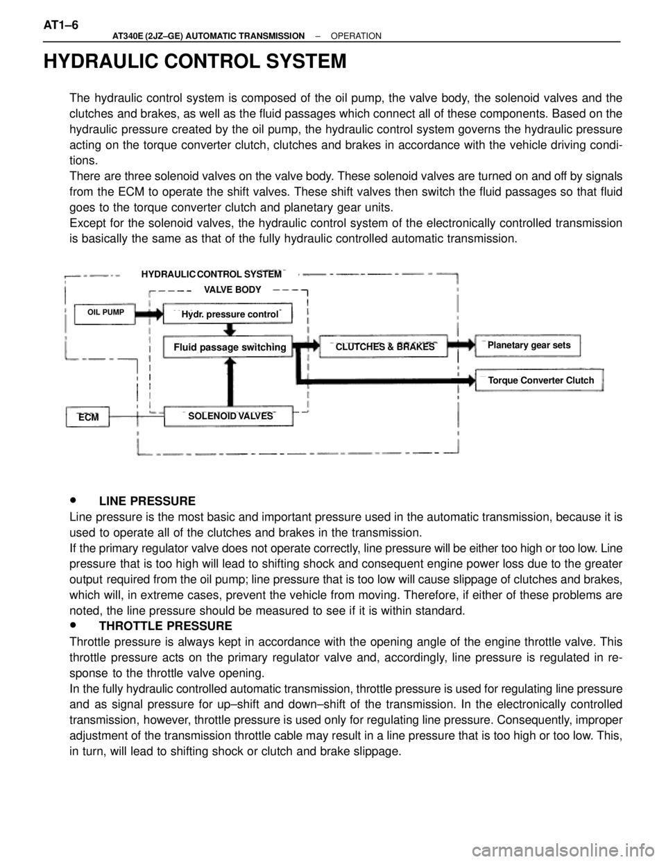
HYDRAULIC CONTROL SYSTEM
The hydraulic control system is composed of the oil pump, the valve body, the solenoid valves and the
clutches and brakes, as well as the fluid passages which connect all of these components. Based on the
hydraulic pressure created by the oil pump, the hydraulic control system governs the hydraulic pressure
acting on the torque converter clutch, clutches and brakes in accordance with the vehicle driving condi-
tions.
There are three solenoid valves on the valve body. These solenoid valves are turned on and off by signals
from the ECM to operate the shift valves. These shift valves then switch the fluid passages so that fluid
goes to the torque converter clutch and planetary gear units.
Except for the solenoid valves, the hydraulic control system of the electronically controlled transmission
is basically the same as that of the fully hydraulic controlled automatic transmission.
HYDRAULIC CONTROL SYSTEM
VALVE BODY
OIL PUMP
ECMSOLENOID VALVES
CLUTCHES & BRAKES
Hydr. pressure control
Fluid passage switchingPlanetary gear sets
Torque Converter Clutch
w LINE PRESSURE
Line pressure is the most basic and important pressure used in the automatic transmission, because it is
used to operate all of the clutches and brakes in the transmission.
If the primary regulator valve does not operate correctly, line pressure will be either too high or too low. Line
pressure that is too high will lead to shifting shock and consequent engine power loss due to the greater
output required from the oil pump; line pressure that is too low will cause slippage of clutches and brakes,
which will, in extreme cases, prevent the vehicle from moving. Therefore, if either of these problems are
noted, the line pressure should be measured to see if it is within standard.
w THROTTLE PRESSURE
Throttle pressure is always kept in accordance with the opening angle of the engine throttle valve. This
throttle pressure acts on the primary regulator valve and, accordingly, line pressure is regulated in re-
sponse to the throttle valve opening.
In the fully hydraulic controlled automatic transmission, throttle pressure is used for regulating line pressure
and as signal pressure for up±shift and down±shift of the transmission. In the electronically controlled
transmission, however, throttle pressure is used only for regulating line pressure. Consequently, improper
adjustment of the transmission throttle cable may result in a line pressure that is too high or too low. This,
in turn, will lead to shifting shock or clutch and brake slippage. AT1±6
± AT340E (2JZ±GE) AUTOMATIC TRANSMISSIONOPERATION
Page 398 of 2543

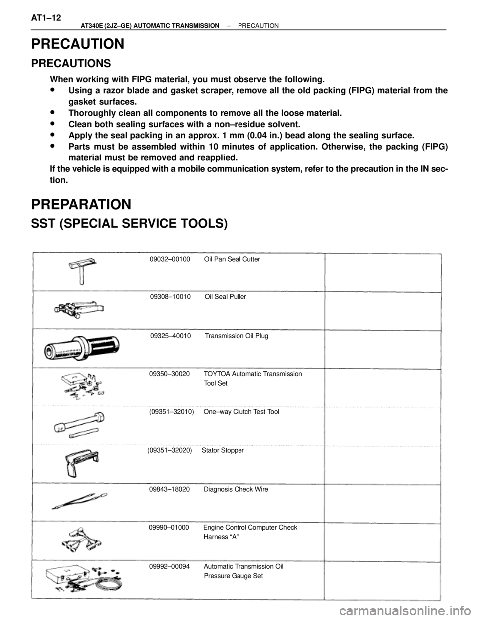
09032±00100 Oil Pan Seal Cutter
09308±10010 Oil Seal Puller
09325±40010 Transmission Oil Plug
09350±30020 TOYTOA Automatic Transmission
Tool Set
(09351±32010) One±way Clutch Test Tool
(09351±32020) Stator Stopper
09843±18020 Diagnosis Check Wire
09990±01000 Engine Control Computer Check
Harness ªAº
09992±00094 Automatic Transmission Oil
Pressure Gauge Set
PRECAUTION
PRECAUTIONS
When working with FIPG material, you must observe the following.
wUsing a razor blade and gasket scraper, remove all the old packing (FIPG) material from the
gasket surfaces.
wThoroughly clean all components to remove all the loose material.
wClean both sealing surfaces with a non±residue solvent.
wApply the seal packing in an approx. 1 mm (0.04 in.) bead along the sealing surface.
wParts must be assembled within 10 minutes of application. Otherwise, the packing (FIPG)
material must be removed and reapplied.
If the vehicle is equipped with a mobile communication system, refer to the precaution in the IN sec-
tion.
PREPARATION
SST (SPECIAL SERVICE TOOLS)
AT1±12± AT340E (2JZ±GE) AUTOMATIC TRANSMISSIONPRECAUTION
Page 434 of 2543

HYDRAULIC TEST
MEASURE LINE PRESSURE
NOTICE:
wDo the test at normal operating fluid temp. 50±80 5C (122±176 5F).
wThe line pressure test should always be carried out in pairs. One technician should observe the
conditions of wheels or wheel stoppers outside the vehicle while the other is doing the test.
wBe careful to prevent the oil pressure gauge hose from interfering with the exhaust pipe.
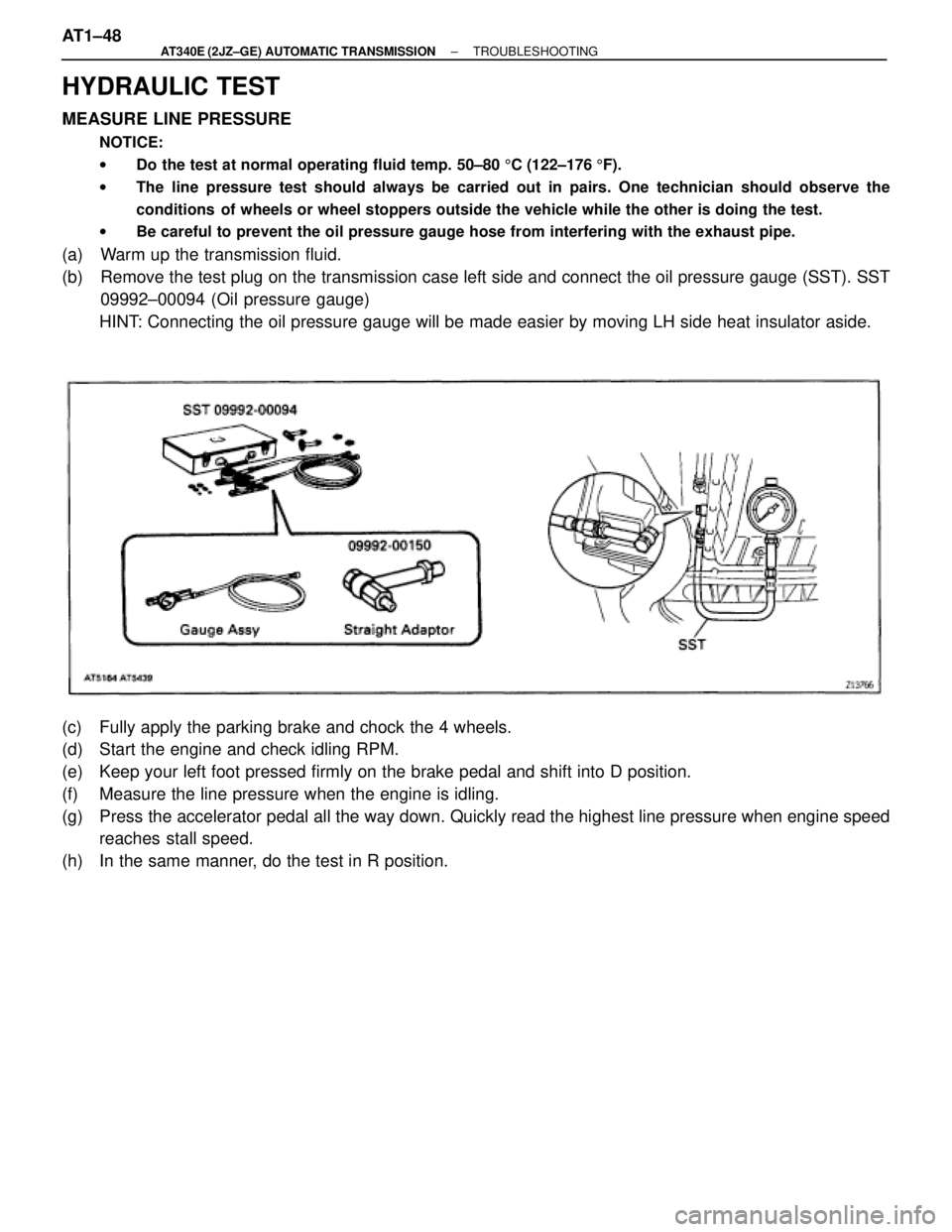
(a) Warm up the transmission fluid.
(b) Remove the test plug on the transmission case left side and connect the oil pressure gauge (SST). SST
09992±00094 (Oil pressure gauge)
HINT: Connecting the oil pressure gauge will be made easier by moving LH side heat insulator aside.
(c) Fully apply the parking brake and chock the 4 wheels.
(d) Start the engine and check idling RPM.
(e) Keep your left foot pressed firmly on the brake pedal and shift into D position.
(f) Measure the line pressure when the engine is idling.
(g) Press the accelerator pedal all the way down. Quickly read the highest line pressure when engine speed
reaches stall speed.
(h) In the same manner, do the test in R position. AT1±48
± AT340E (2JZ±GE) AUTOMATIC TRANSMISSIONTROUBLESHOOTING