Page 452 of 2543

DTC 42 No. 1 Vehicle Speed Sensor Signal Circuit
CIRCUIT DESCRIPTION
The No. 1 vehicle speed sensor outputs a 4±pulse signal for every revolution of the rotor shaft, which
is rotated by the transmission output shaft via the driven gear. After this signal is converted into a more
precise rectangular waveform by the waveform shaping circuit inside the combination meter, it is then
transmitted to the ECM. The ECM determines the vehicle speed based on the frequency of these pulse
signals.
All conditions below are detected 500 times or more
continuously. (2 trip detection logic)*
Diagnostic Trouble Code Detection ConditionDTC No.Trouble Area
No. No. 1 vehicle speed sensor signal in 16
pulses of No. 2 vehicle speed sensor signal.
Vehicle speed: 9 km/h (5.6 mph) or more for 4
secs. or more for 4 secs. or more.
Park/neutral position switch:
OFF (Other than P or N position)
42
No. 1 vehicle speed sensor
Telltale light RH
Harness or connector between No. 1 vehicle
speed sensor and ECM
ECM
HINT: In test more, diagnostic trouble code 42 is output when vehicle speed is 5 km/h (3 mph) or
below.
See page AT1±54
< Reference >
HINT: As the vehicle's speed increases, the signal output from
SP1 increases.
Waveform between terminals SP1 and E2 when vehicle speed is approx. 20 km/h (12 mph).
± AT340E (2JZ±GE) AUTOMATIC TRANSMISSIONTROUBLESHOOTINGAT1±66
Page 454 of 2543
Replace No. 1 vehicle speed sensor.
Repair or replace harness or connector between tell-
tale light RH and No. 1 vehicle speed sensor.
Check operation of No. 1 vehicle speed sensor (See page BR±46).
AT1±68± AT340E (2JZ±GE) AUTOMATIC TRANSMISSIONTROUBLESHOOTING
Page 455 of 2543

DTC 61 No. 2 Vehicle Speed Sensor Circuit
CIRCUIT DESCRIPTION
The No. 2 vehicle speed sensor detects the rotation speed of the transmission output shaft and sends
signals to the ECM. The ECM determines the vehicle speed based on these signals. An AC voltage
is generated in the No.2 vehicle speed sensor coil as the rotor mounted on the output shaft rotates,
and this voltage is sent to the ECM.
The gear shift point and lock±up timing are controlled by the ECM based on the signals from this vehicle
speed sensor and the throttle position sensor signal.
If the No.2 vehicle speed sensor malfunctions, the ECM uses input signals from the No.1 vehicle speed
sensor as a back±up signal.
See page AT1±54
All conditions below are detected 500 times or more
continuously. (2 trip detection logic)*
Diagnostic Trouble Code Detection ConditionDTC No.Trouble Area
No. No. 2 vehicle speed sensor signal in 4
pulses of No. 2 vehicle speed sensor signal.
Vehicle speed: 9 km/h (5.6 mph) or more for 4
secs. or more for 4 secs. or more.
Park/neutral position switch:
OFF (Other than P or N position)
61
No. 2 vehicle speed sensor
Harness or connector between No. 2 vehicle
speed sensor and ECM
ECM
< Reference >Waveform between terminals SP2± and SP2± when vehicle
speed is approx. 60 km/h (37 mph).
± AT340E (2JZ±GE) AUTOMATIC TRANSMISSIONTROUBLESHOOTINGAT1±69
Page 457 of 2543
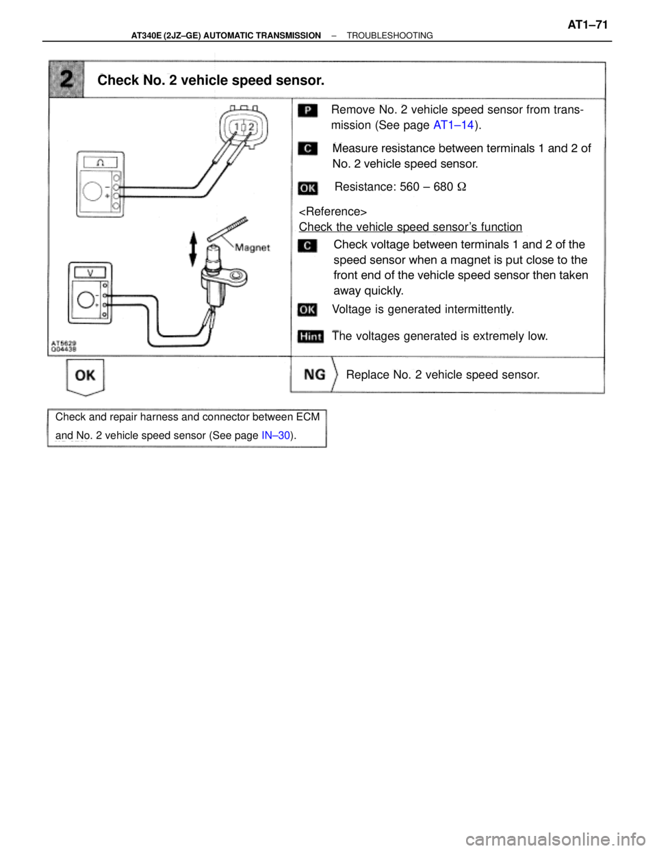
Remove No. 2 vehicle speed sensor from trans-
mission (See page AT1±14).
Measure resistance between terminals 1 and 2 of
No. 2 vehicle speed sensor.
Resistance: 560 ± 680 �
Voltage is generated intermittently.
Check No. 2 vehicle speed sensor.
Check voltage between terminals 1 and 2 of the
speed sensor when a magnet is put close to the
front end of the vehicle speed sensor then taken
away quickly.
The voltages generated is extremely low.
Replace No. 2 vehicle speed sensor.
Check and repair harness and connector between ECM
and No. 2 vehicle speed sensor (See page IN±30).
Check the vehicle speed sensor's function
± AT340E (2JZ±GE) AUTOMATIC TRANSMISSIONTROUBLESHOOTINGAT1±71
Page 463 of 2543
Throttle Position Sensor Circuit
CIRCUIT DESCRIPTION
The throttle position sensor detects the throttle valve opening angle and sends signals to ECM.
WIRING DIAGRAM
± AT340E (2JZ±GE) AUTOMATIC TRANSMISSIONTROUBLESHOOTINGAT1±77
Page 464 of 2543
INSPECTION PROCEDURE
(See page EG±219).
Turn ignition switch ON.
Do not depress the brake pedal during this test.
The voltage will stay at 0 V if depressed.
Voltage changes from 0 V to 8 V by stages.
Check throttle position signal.
Check voltage at the terminal TT of the DLC2
while gradually depressing the accelerator pedal
from the fully closed position to the fully opened
position.
Proceed to next circuit inspection shown on
matrix chart (See page AT1±58).
Replace throttle position sensor.
Repair or replace harness or connector.
Check and replace ECM.
Check harness and connector between ECM and throttle position sen-
sor (See page IN±30).
AT1±78± AT340E (2JZ±GE) AUTOMATIC TRANSMISSIONTROUBLESHOOTING
Page 471 of 2543
Pattern Select Switch Circuit
CIRCUIT DESCRIPTION
The ECM memory contains the shift programs for the NORMAL and MANUAL patterns, 2 position, and L posi-
tion and the lock±up patterns. Following the programs corresponding to the signals from the pattern select
switch, the park/neutral position switch and other various sensors the ECM switches the solenoid valves ON
and OFF, thereby controlling the transmission gear change and the lock±up clutch operation.
WIRING DIAGRAM
INSPECTION PROCEDURE
Check A/T fluid temp. sensor. (See page AT1±64).
Replace A/T fluid temp. sensor.
± AT340E (2JZ±GE) AUTOMATIC TRANSMISSIONTROUBLESHOOTINGAT1±85
Page 481 of 2543
TT Terminal Circuit
CIRCUIT DESCRIPTION
Checks of ECM input and output signals related to the throttle position sensor, brakes, shift position and other
circuits can be performed by measuring the voltages at terminal TT of the DLC2
INSPECTION PROCEDURE
Repair or replace harness or connector.
Check and replace ECM.
Check harness and connector between ECM and DLC2 and body ground
(See page IN±30).
± AT340E (2JZ±GE) AUTOMATIC TRANSMISSIONTROUBLESHOOTINGAT1±95
.")
 AUTOMATIC TRANSM")
.
Turn ignition switch ON.
Do not depress the brake pedal during this test.
The voltage will stay at 0 V if depressed.
Voltage changes from 0 V to 8 V by stages.")

