Page 422 of 2543

CHECK TERMINAL TT OUTPUT
VOLTAGE
When a voltmeter is connected to the DLC2, the following
items can be checked:
1. Throttle position sensor signal
2. Brake signal
3. Shift position signal
1. VOLTMETER CONNECTION
Connect the positive (+) probe of the voltmeter to terminal TT
and the negative (±) probe to terminal E1 of the DLC2.
HINT: If a voltmeter with small internal resistance is used, the
correct voltage will not be indicated, so use a voltmeter with
an internal resistance of at least 10 k�/V.
2. TURN IGNITION SWITCH TO ON (DO NOT START THE
ENGINE)
3. CHECK THROTTLE POSITION SENSOR SIGNAL
Check if the voltage changes from approx. 0 V to approx. 8
V when the accelerator pedal is gradually depressed from the
fully closed position.
4. CHECK BRAKE SIGNAL (LOCK±UP CUT SIGNAL)
(a) Open the throttle valve fully to apply approx. 8 V to terminal
TT.
(b) In this condition, check terminal TT voltage when the brake
pedal is depressed and released.
TT terminal voltage:
0 V (When brake pedal is depressed)
8 V (When brake pedal is released)
5. START ENGINE
6. CHECK SHIFT POSITION SIGNAL
(VEHICLE SPEED ABOVE 9 km/h, 6 mph)
Check up±shifting together with terminal TT voltage.
HINT: Check for light shocks from up±shifting and for
changes in the tachometer.
����������� �
���������� �����������Gear Position
������������ �
����������� ������������Terminal TT output voltage
�����������1st Gear0V����������� �����������1st Gear0 V
�����������2nd Gear2V����������� �����������2nd Gear2 V
����������� �����������2nd Lock up3V�����������2nd Lock±up3 V����������� �����������
3rd Gear4V����������� �����������3rd Gear4 V
�����������3rd Lock up5V����������� �����������3rd Lock±up5 V
�����������O/D6V����������� �����������O/D6 V
����������� �����������O/D Lock up7V�����������O/D Lock±up7 V
If terminal TT output voltage check cannot be done, do the
check of TT terminal circuit on page AT1±95. AT1±36
± AT340E (2JZ±GE) AUTOMATIC TRANSMISSIONTROUBLESHOOTING
Page 438 of 2543
 or (b) are detected for 0.5 sec. or more.
(a) Temperature sensor resistance less than 79 �
(b) After the engi")
DTC
No.Blinking
PatternCircuitDiagnostic Trouble Code Detection Condition
38
42
Either (a) or (b) are detected for 0.5 sec. or more.
(a) Temperature sensor resistance less than 79 �
(b) After the engine has been operating for 15 minutes or more,
the resistance at the temperature sensor is more than 156 k�
All conditions below are detected 500 times or more continuously.
(2 trip detection logic) *3
(a) No No. 1 vehicle speed sensor signal in 16 pulses of No. 2
vehicle speed sensor signal.
(b) Vehicle speed: 9 km/h (5.6 mph) or more for 4 secs. or more.
(c) Park/neutral position switch: OFF (Other than P or N position)
A/T fluid
temp.
sensor
No. 1 vehicle
speed sensor
No. 2 vehicle
speed sensor
All conditions below are detected 500 times or more continuously.
(2 trip detection logic) *3
(a) No No. 2 vehicle speed sensor signal in 4 pulses of No. 1
vehicle speed sensor signal.
(b) Vehicle speed: 9 km/h (5.6 mph) or more for 4 secs. or more.
(c) Park/neutral position switch: OFF (Other than P or N position)
No. 1
solenoid
valve
(1) Solenoid resistance of 8 ��or less is detected (*) 8 times or
more when No. 1 solenoid is energized.
(2) Solenoid resistance of 100 k� or more is detected (*) 8 times
or more when No. 1 solenoid is not energized.
(*) If the above failures are detected less than 8 times, the ECM
memorizes the malfunction code but the O/D OFF indicator
light does not blink.
No. 2
solenoid
valve
(1) Solenoid resistance of 8 ��or less is detected (*) 8 times or
more when No. 2 solenoid is energized.
(2) Solenoid resistance of 100 k� or more is detected (*) 8 times
or more when No. 2 solenoid is not energized.
(*) If the above failures are detected less than 8 times, the ECM
memorizes the malfunction code but the O/D OFF indicator
light does not blink.
Lock±up
solenoid
valve
(a) Solenoid resistance is 8 ��or lower (short circuit) when
solenoid energized.
(b) Solenoid resistance is 100 k� or higher (open circuit) when
solenoid is not energized.
(*) ECM memorizes diag. trouble code 64 if above (a) or (b)
condition is detected once or more, but ECM does not start
O/D OFF indicator light blinking.
61
62
63
64
DIAGNOSTIC TROUBLE CODE CHART
If a diagnostic trouble code is displayed during the diagnostic trouble code check, check the circuit listed
for that code in the table below and proceed to the page given. AT1±52
± AT340E (2JZ±GE) AUTOMATIC TRANSMISSIONTROUBLESHOOTING
Page 439 of 2543
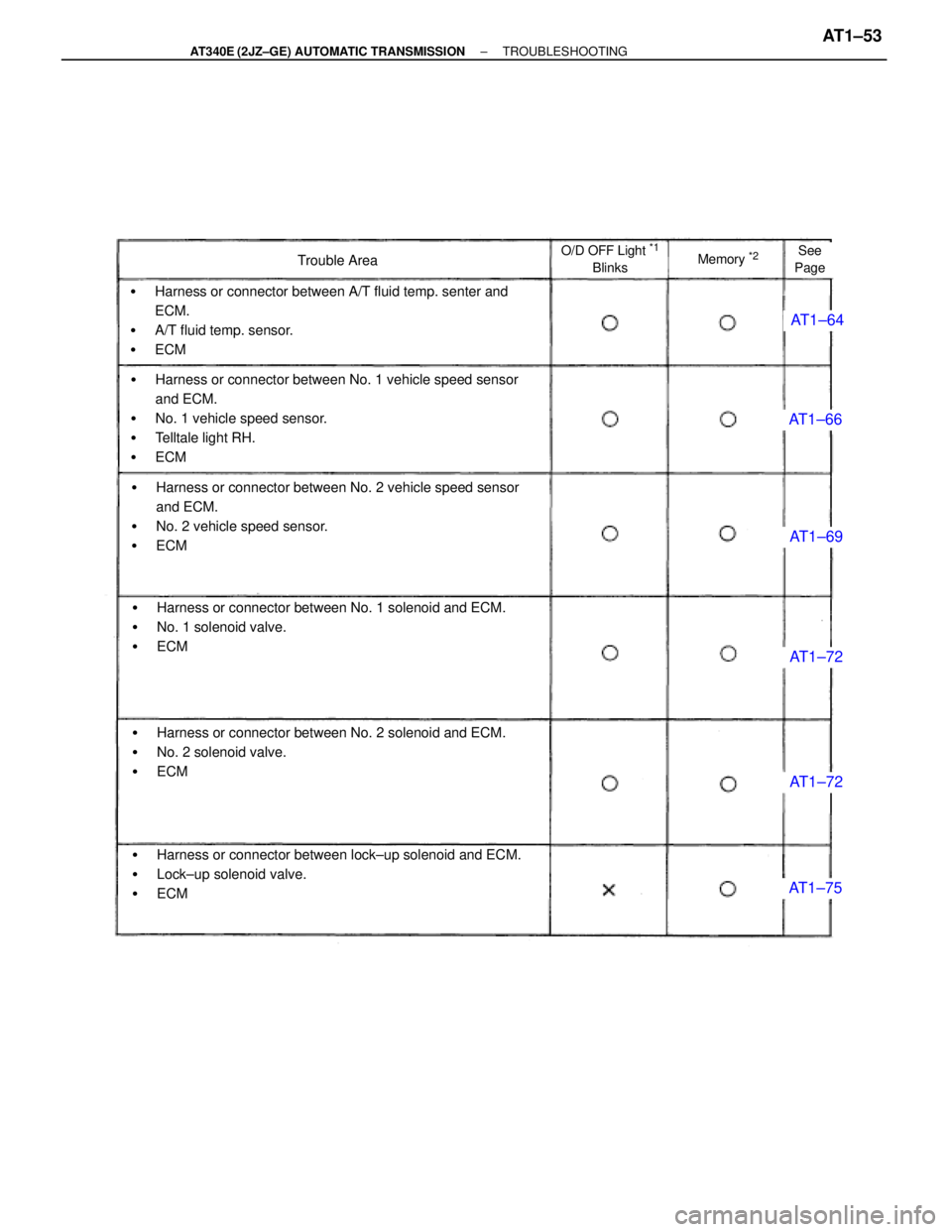
AT1±64
AT1±66
AT1±69
AT1±72
AT1±72
AT1±75
Trouble AreaO/D OFF Light *1
BlinksMemory *2See
Page
�Harness or connector between A/T fluid temp. senter and
ECM.
�A/T fluid temp. sensor.
�ECM
�Harness or connector between No. 1 vehicle speed sensor
and ECM.
�No. 1 vehicle speed sensor.
�Telltale light RH.
�ECM
�Harness or connector between No. 2 vehicle speed sensor
and ECM.
�No. 2 vehicle speed sensor.
�ECM
�Harness or connector between No. 1 solenoid and ECM.
�No. 1 solenoid valve.
�ECM
�Harness or connector between No. 2 solenoid and ECM.
�No. 2 solenoid valve.
�ECM
�Harness or connector between lock±up solenoid and ECM.
�Lock±up solenoid valve.
�ECM
± AT340E (2JZ±GE) AUTOMATIC TRANSMISSIONTROUBLESHOOTINGAT1±53
Page 440 of 2543

*1 ª�º mark means ºO/D OFFº indicator light blinks once every 2 seconds.
ºXº mark means ºO/D OFFº indicator light never blinks.
*
2ª�º marks means the ECM memorizes the malfunction code if the ECM detects the diagnostic trouble code
detection condition.
*
3 This indicates items for which º2 trip detection logicº is used. With this logic, when a logic malfunction is
first detected, the malfunction is temporarily stored in the ECM memory. If the same case is detected again
during the second drive test, this second detection causes the O/D OFF Indicator Light to blink. The 2 trip
repeats the same mode twice. (However, the IG switch must be turned OFF between the 1st trip and 2nd
trip.)
HINT:
wIf the malfunction returns to normal while a malfunction warning is being output, the O/D OFF indicator
light stops blinking and goes off.
However, the diagnostic trouble code is retained in memory until it is cleared from memory.
wIf the diagnosis system outputs a diagnostic trouble code even though the O/D OFF indicator was not
blinking, there is intermittent trouble. Check all the connections in the circuits corresponding to that
code.
wIf the vehicle speed sensors No.1 and No.2 happen to fail simultaneously, the ECM will neither alert
the driver by blinking the O/D OFF indicator nor record any diagnostic trouble code. It will, however,
decide that the vehicle can be driven only in 1st and none of the other gears, so shifting upward will
then be prohibited.
wCodes 46, 62, 63 and 64 are limited to short or open circuits in the electrical system comprised of the
solenoids, wire harnesses, and connectors. The ECM is unable to detect mechanical trouble (sticking,
for example) in the solenoid valves. AT1±54
± AT340E (2JZ±GE) AUTOMATIC TRANSMISSIONTROUBLESHOOTING
Page 444 of 2543

Chapter 1. Electronic Circuit
AT1±66AT1±69AT1±72AT1±75AT1±77AT1±81AT1±79
No.1 Vehicle speedsensor circuitNo.2 Vehicle speed
sensor circuitNo.1, No.2 Sole-
noid circuitkick±down switch
circuitThrottle position
sensor circuitSL Solenoid
circuitPark/neutral posi-
tion switch circuit
See Page
Suspect Area
Symptom
Vehicle does not move in any forward position and reverse position
Vehicle does not move in particular position or positions
No up±shift
No down±shift
No lock±up
No lock±up off
Shift point too high or too low
Up±shifts to 2nd while in L positionUp±shifts to 3rd while in L position
Up±shifts to O/D from 3rd while O/D switch is OFF
Up±shifts to O/D from 3rd while engine is cold
Harsh engagement
Slip or Shudder
Poor acceleration
No kick±down
No engine braking
No pattern select*
Large shift shock or engine stalls when starting off or stopping.
Any particular position
Forward and reverse
Any driving position
Lock±up
N " D
1st " 2nd
2nd " 3rd
3rd " O/D
O/D " 3rd
3rd " 2nd
2nd " 1st
* The automatic transmission is not shifted into the manual mode when the automatic transmission
fluid temperature is too high. AT1±58
± AT340E (2JZ±GE) AUTOMATIC TRANSMISSIONTROUBLESHOOTING
Page 445 of 2543
AT1±83AT1±85AT1±88AT1±91AT1±64EG±312AT1±56AT1±60AT1±62
Stop light switch
circuitPattern select switch
circuitO/D switch O/D OFF
indicator light circuitECMA/T fluid temp.
sensor circuitO/D cancel signal
circuitEngine coolant
temp. switch circuitOFF±Vehicle repairmatrix chartOn±Vehicle repairmatrix chart
± AT340E (2JZ±GE) AUTOMATIC TRANSMISSIONTROUBLESHOOTINGAT1±59
Page 450 of 2543
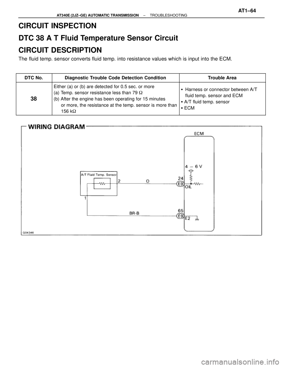
CIRCUIT INSPECTION
DTC 38 A T Fluid Temperature Sensor Circuit
CIRCUIT DESCRIPTION
The fluid temp. sensor converts fluid temp. into resistance values which is input into the ECM.
������ ������DTC No.������������������� �������������������Diagnostic Trouble Code Detection Condition������������� �������������Trouble Area
������ �
����� �
����� �
����� �
����� ������
38
������������������� �
������������������ �
������������������ �
������������������ �
������������������ �������������������
Either (a) or (b) are detected for 0.5 sec. or more
(a) Temp. sensor resistance less than 79 �
(b) After the engine has been operating for 15 minutes
or more, the resistance at the temp. sensor is more than
156 k�������������� �
������������ �
������������ �
������������ �
������������ �������������
�Harness or connector between A/T
fluid temp. sensor and ECM
� A/T fluid temp. sensor
� ECM
± AT340E (2JZ±GE) AUTOMATIC TRANSMISSIONTROUBLESHOOTINGAT1±64
Page 451 of 2543
INSPECTION PROCEDURE
Check sensor resistance
Remove A/T fluid temp. sensor.
Measure resistance between terminals of A/T fluid
temp. sensor at 20°C (68°F) and 110°C (230°F).
Resistance:
20°C (68°F) Approx. 12.08 k�
110°C (230°F) Approx. 0.78 k�
Replace A/T fluid temp. sensor.
Repair or replace harness or connector.
Check harness and connector between battery and A/T fluid temp. sensor
A/T fluid temp. sensor and ECM. (See page IN±30).
Check A/T fluid temp. sensor.
Check and replace ECM. AT1±65
± AT340E (2JZ±GE) AUTOMATIC TRANSMISSIONTROUBLESHOOTING

 and 110°C (230°F).
Resistance:
20°C")