Page 1243 of 2543
BRAKES
13. INSPECT BRAKE LINE PIPES AND HOSES
HINT: Check in a well lighted area. Check the entire circum-
ference and length of the brake hoses using a mirror as re-
quired. Turn the front wheels fully right or left before checking
the front brake.
(a) Check all brake lines and hoses for:
wDamage
wWear
wDeformation
wCracks
wCorrosion
wLeaks
wBends
wTwists
(b) Check all clamps for tightness and connections for leakage.
(c) Check that the hoses and lines are clear of sharp edges,
moving parts and the exhaust system.
(d) Check that the lines installed in grommets pass through the
center of the grommets.
MA±10± MAINTENANCEMAINTENANCE OPERATIONS
Page 1245 of 2543

wDrive the vehicle at approx. 50 km/h (30 mph) on a safe,
level and dry road.
wWith the parking brake button pushed in, pull on the
lever with 88 N (9 kgf, 20 lbf) of force.
wDrive the vehicle for approx. 400 meters (1/4 mile) in this
condition.
wRepeat this procedure 2 or 3 times.
wCheck parking lever travel.
If necessary, adjust the parking brake.
CHASSIS
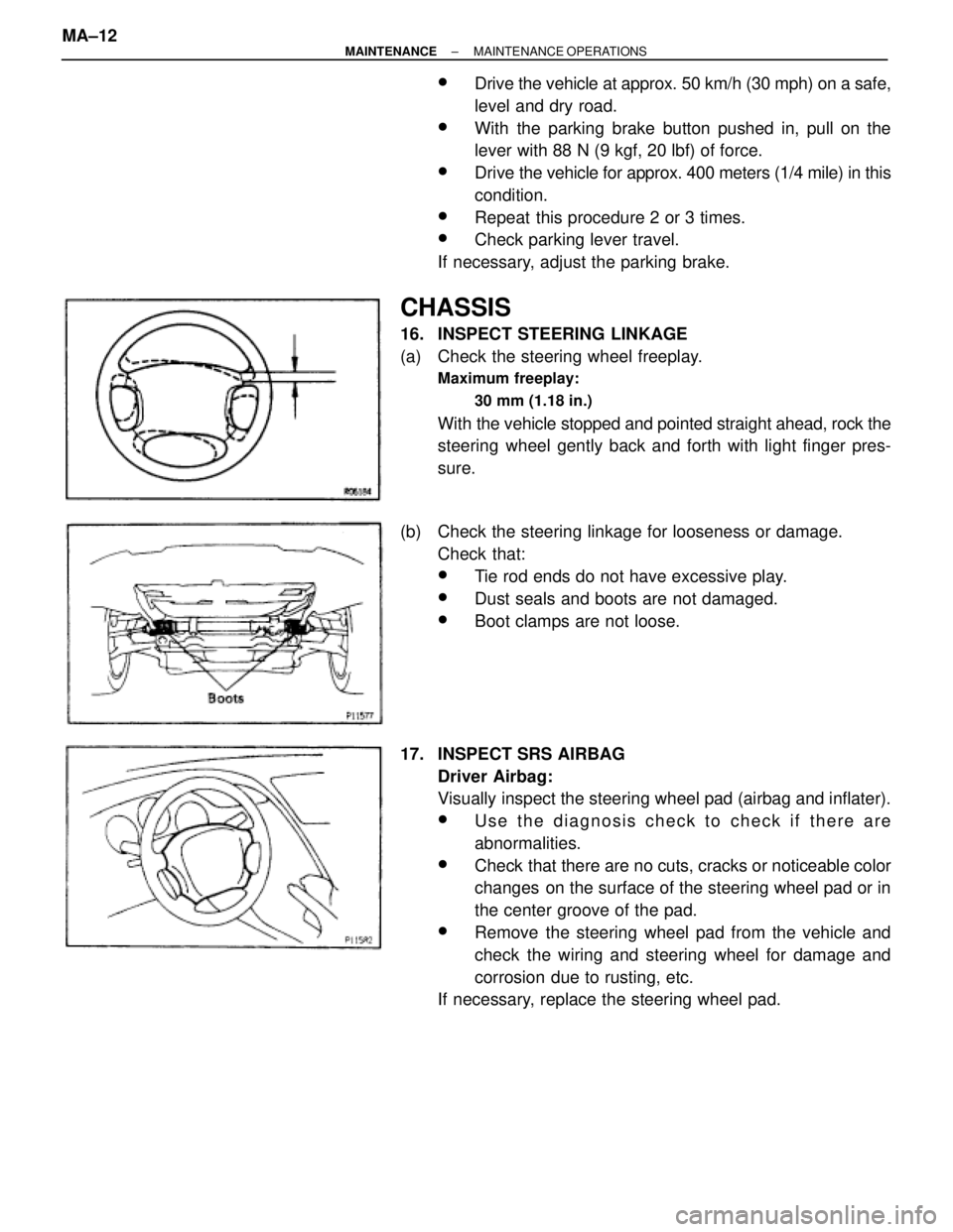
16. INSPECT STEERING LINKAGE
(a) Check the steering wheel freeplay.
Maximum freeplay:
30 mm (1.18 in.)
With the vehicle stopped and pointed straight ahead, rock the
steering wheel gently back and forth with light finger pres-
sure.
(b) Check the steering linkage for looseness or damage.
Check that:
wTie rod ends do not have excessive play.
wDust seals and boots are not damaged.
wBoot clamps are not loose.
17. INSPECT SRS AIRBAG
Driver Airbag:
Visually inspect the steering wheel pad (airbag and inflater).
wUse the diagnosis check to check if there are
abnormalities.
wCheck that there are no cuts, cracks or noticeable color
changes on the surface of the steering wheel pad or in
the center groove of the pad.
wRemove the steering wheel pad from the vehicle and
check the wiring and steering wheel for damage and
corrosion due to rusting, etc.
If necessary, replace the steering wheel pad. MA±12
± MAINTENANCEMAINTENANCE OPERATIONS
Page 1832 of 2543

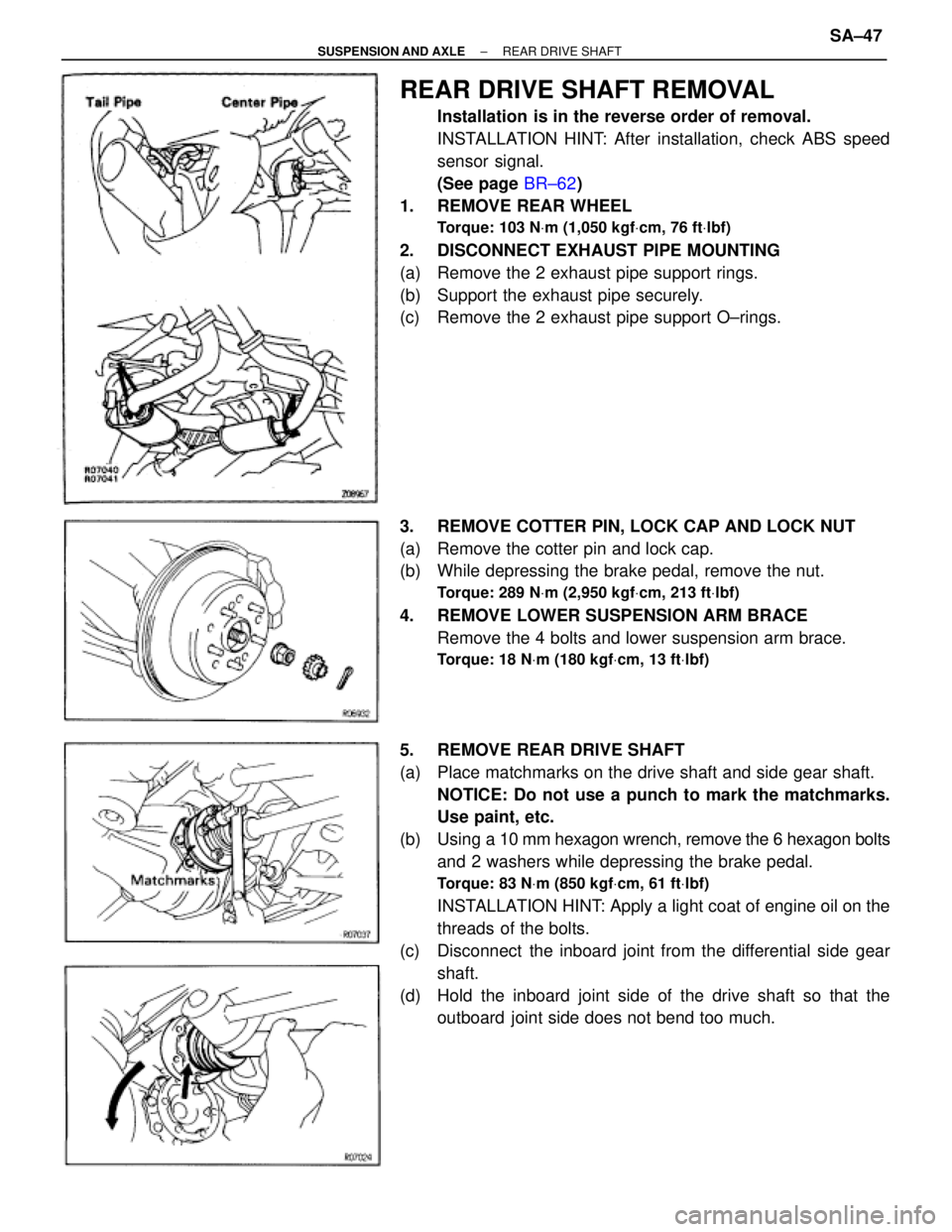
REAR DRIVE SHAFT REMOVAL
Installation is in the reverse order of removal.
INSTALLATION HINT: After installation, check ABS speed
sensor signal.
(See page BR±62)
1. REMOVE REAR WHEEL
Torque: 103 NVm (1,050 kgfVcm, 76 ftVlbf)
2. DISCONNECT EXHAUST PIPE MOUNTING
(a) Remove the 2 exhaust pipe support rings.
(b) Support the exhaust pipe securely.
(c) Remove the 2 exhaust pipe support O±rings.
3. REMOVE COTTER PIN, LOCK CAP AND LOCK NUT
(a) Remove the cotter pin and lock cap.
(b) While depressing the brake pedal, remove the nut.
Torque: 289 NVm (2,950 kgfVcm, 213 ftVlbf)
4. REMOVE LOWER SUSPENSION ARM BRACE
Remove the 4 bolts and lower suspension arm brace.
Torque: 18 NVm (180 kgfVcm, 13 ftVlbf)
5. REMOVE REAR DRIVE SHAFT
(a) Place matchmarks on the drive shaft and side gear shaft.
NOTICE: Do not use a punch to mark the matchmarks.
Use paint, etc.
(b) Using a 10 mm hexagon wrench, remove the 6 hexagon bolts
and 2 washers while depressing the brake pedal.
Torque: 83 NVm (850 kgfVcm, 61 ftVlbf)
INSTALLATION HINT: Apply a light coat of engine oil on the
threads of the bolts.
(c) Disconnect the inboard joint from the differential side gear
shaft.
(d) Hold the inboard joint side of the drive shaft so that the
outboard joint side does not bend too much.
± SUSPENSION AND AXLEREAR DRIVE SHAFTSA±47