Page 1009 of 2543

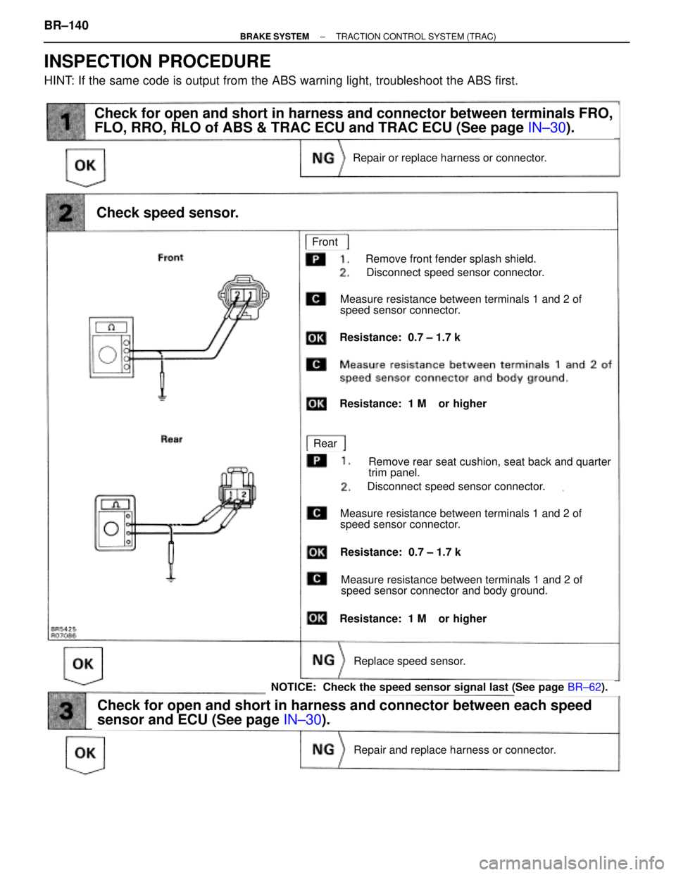
(See page IN±30).
(See page IN±30).
(See page BR±62).
Remove front fender splash shield.
Disconnect speed sensor connector.
Measure resistance between terminals 1 and 2 of
speed sensor connector.
Resistance: 0.7 ± 1.7 k�
Resistance: 1 M� or higher
Remove rear seat cushion, seat back and quarter
trim panel.
Disconnect speed sensor connector.
Measure resistance between terminals 1 and 2 of
speed sensor connector.
Resistance: 0.7 ± 1.7 k�
Measure resistance between terminals 1 and 2 of
speed sensor connector and body ground.
Resistance: 1 M� or higher
Repair or replace harness or connector.
Check speed sensor.
Check for open and short in harness and connector between terminals FRO,
FLO, RRO, RLO of ABS & TRAC ECU and TRAC ECU (See page IN±30).
Front
Rear
Replace speed sensor.
NOTICE: Check the speed sensor signal last (See page BR±62).
Check for open and short in harness and connector between each speed
sensor and ECU (See page IN±30).
Repair and replace harness or connector.
INSPECTION PROCEDURE
HINT: If the same code is output from the ABS warning light, troubleshoot the ABS first. BR±140
± BRAKE SYSTEMTRACTION CONTROL SYSTEM (TRAC)
Page 1024 of 2543

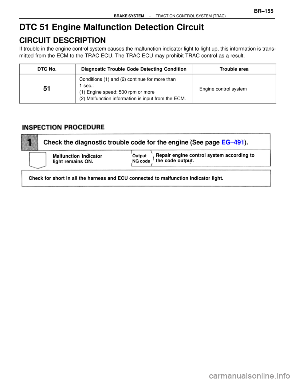
Check the diagnostic trouble code for the engine (See page EG±491).
Check for short in all the harness and ECU connected to malfunction indicator light.
Repair engine control system according to
the code output.Malfunction indicator
light remains ON.Output
NG code
DTC 51 Engine Malfunction Detection Circuit
CIRCUIT DESCRIPTION
If trouble in the engine control system causes the malfunction indicator light to light up, this information is trans-
mitted from the ECM to the TRAC ECU. The TRAC ECU may prohibit TRAC control as a result.
��������� �
��������DTC No.����������������� �
����������������Diagnostic Trouble Code Detecting Condition������������ �
�����������Trouble area��������� �
�������� �
�������� �
�������� �
��������
51
����������������� �
���������������� �
���������������� �
���������������� �
����������������
Conditions (1) and (2) continue for more than
1 sec.:
(1) Engine speed: 500 rpm or more
(2) Malfunction information is input from the ECM.
������������ �
����������� �
����������� �
����������� �
�����������
� Engine control system
± BRAKE SYSTEMTRACTION CONTROL SYSTEM (TRAC)BR±155
Page 1025 of 2543

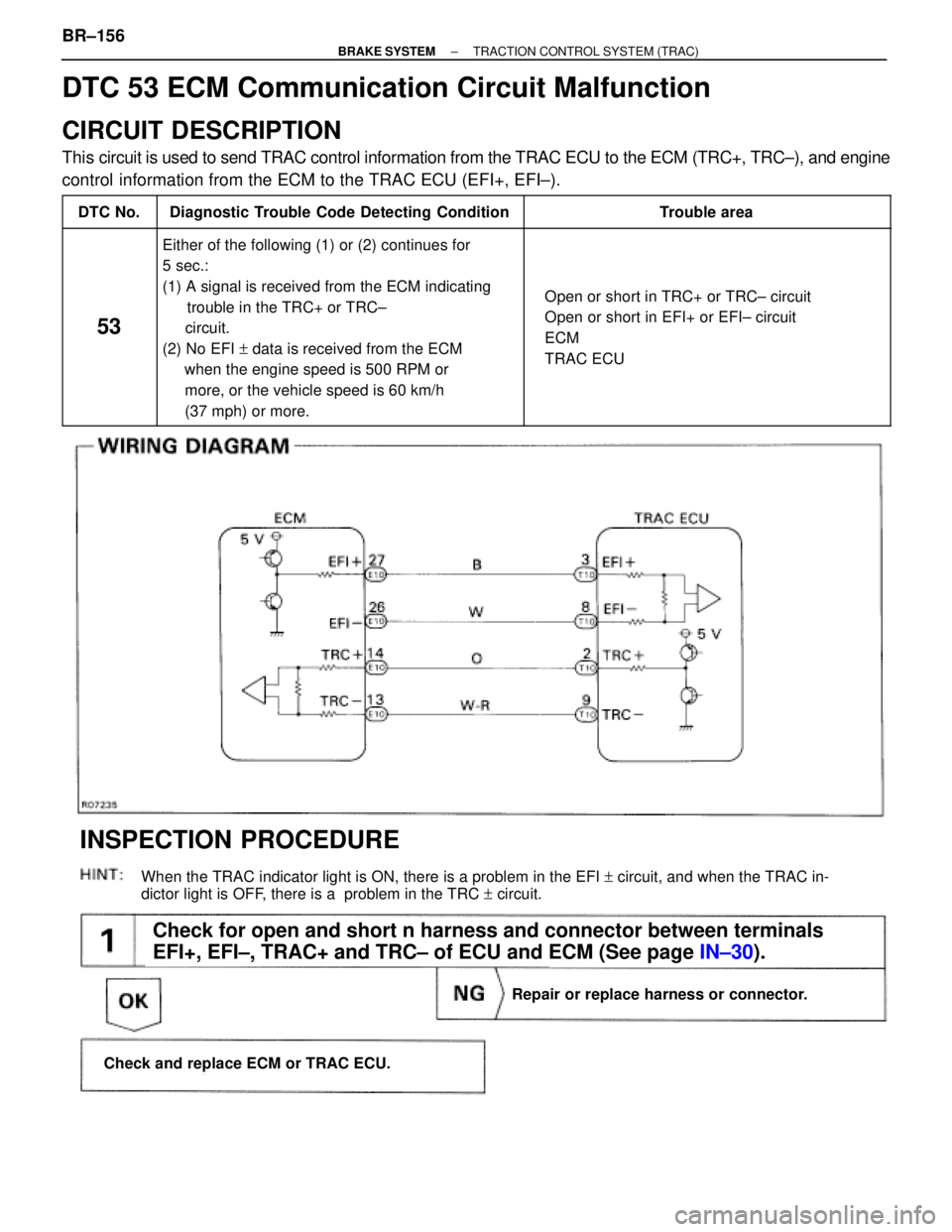
(See page IN±30).
Check for open and short n harness and connector between terminals
EFI+, EFI±, TRAC+ and TRC± of ECU and ECM (See page IN±30).
When the TRAC indicator light is ON, there is a problem in the EFI + circuit, and when the TRAC in-
dictor light is OFF, there is a problem in the TRC + circuit.
Repair or replace harness or connector.
Check and replace ECM or TRAC ECU.
INSPECTION PROCEDURE
DTC 53 ECM Communication Circuit Malfunction
CIRCUIT DESCRIPTION
This circuit is used to send TRAC control information from the TRAC ECU to the ECM (TRC+, TRC±), and engine
control information from the ECM to the TRAC ECU (EFI+, EFI±).
����� �����DTC No.���������������� ����������������Diagnostic Trouble Code Detecting Condition����������������� �����������������Trouble area
����� �
���� �
���� �
���� �
���� �
���� �
���� �
���� �����
53
���������������� �
��������������� �
��������������� �
��������������� �
��������������� �
��������������� �
��������������� �
��������������� ����������������
Either of the following (1) or (2) continues for
5 sec.:
(1) A signal is received from the ECM indicating
trouble in the TRC+ or TRC±
circuit.
(2) No EFI + data is received from the ECM
when the engine speed is 500 RPM or
more, or the vehicle speed is 60 km/h
(37 mph) or more.����������������� �
���������������� �
���������������� �
���������������� �
���������������� �
���������������� �
���������������� �
���������������� �����������������
� Open or short in TRC+ or TRC± circuit
� Open or short in EFI+ or EFI± circuit
� ECM
� TRAC ECU
BR±156± BRAKE SYSTEMTRACTION CONTROL SYSTEM (TRAC)
Page 1028 of 2543
TRAC OFF Indicator TRAC Cut Switch Circuit
CIRCUIT DESCRIPTION
This is the TRAC control main switch. When the TRAC cut switch is pushed on, TRAC control goes off and the
TRAC OFF indicator lights up. This indicator is also used for warnings when the trouble occurs.
± BRAKE SYSTEMTRACTION CONTROL SYSTEM (TRAC)BR±159
Page 1029 of 2543
page BR±126.
page BR±43.
(See page IN±30).
Is diagnostic trouble code output?
Check for open and short in harness and connector between terminal CSW
of TRAC ECU and TRAC cut switch and body ground (See page IN±30).
1. Remove TRAC cut switch.
2. Disconnect TRAC cut switch connector.
Measure resistance between terminals 1 and 2 of
TRAC cut switch when TRAC cut switch is on and
off.
Do diagnostic trouble code check on page BR 126.
Repair circuit indicated by the code output.
Replace TRAC cut switch.
Repair or replace harness or connector.
Check TRAC OFF indicator light.
See Combination Meter Troubleshooting on page BR±43.
Check TRAC cut switch.
TRAC car switch
Pushed in
Released
Continuity
1 M� or higher
Resistance
INSPECTION PROCEDURE
BR±160± BRAKE SYSTEMTRACTION CONTROL SYSTEM (TRAC)
Page 1031 of 2543
TRAC Indicator Light Circuit
CIRCUIT DESCRIPTION
The TRAC indicator blinks during TRAC operation.
This indicator is also used for warnings when the trouble occurs and for displaying diagnostic trouble
codes.
Repair or replace harness or connector.
Check and replace TRAC ECU.
Repair circuit indicated by the code output.
Check diagnostic trouble code (See page BR±126).
INSPECTION PROCEDURES
Troubleshoot in accordance with flow chart instructions for each trouble symptom.
TRAC Indicator light does not light up
Go to Combination Meter Troubleshooting on page BE±43.
TRAC Indicator light remains ON
Check for short in harness and connector between TRAC ECU and TRAC
indicator light (See page IN±30).
Indicator light remains ONOutput
NG Code
BR±162± BRAKE SYSTEMTRACTION CONTROL SYSTEM (TRAC)
Page 1032 of 2543
Tc Terminal Circuit
CIRCUIT DESCRIPTION
By connecting terminals Tc and E1 of DLC1 or DLC2, the ECU displays the diagnostic trouble code
by blinking the TRAC indicator light.
± BRAKE SYSTEMTRACTION CONTROL SYSTEM (TRAC)BR±163
Page 1204 of 2543

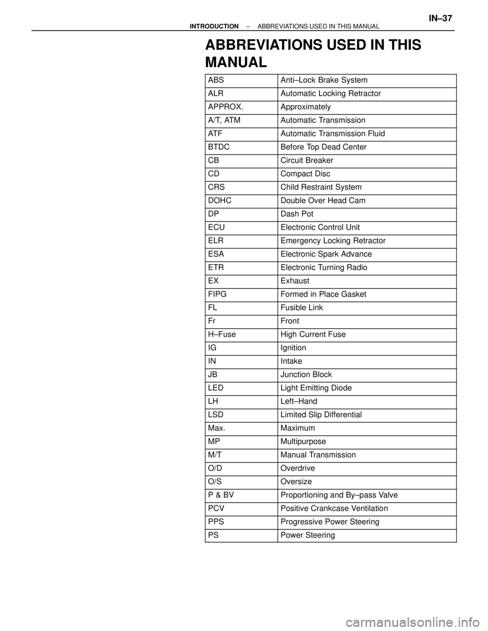
ABBREVIATIONS USED IN THIS
MANUAL
������� �������ABS���������������� ����������������Anti±Lock Brake System
������� �������ALR���������������� ����������������Automatic Locking Retractor
������� �������APPROX.���������������� ����������������Approximately
������� �������A/T, ATM���������������� ����������������Automatic Transmission
������� �������AT F���������������� ����������������Automatic Transmission Fluid
������� �������BTDC���������������� ����������������Before Top Dead Center
������� �������CB���������������� ����������������Circuit Breaker
������� �������CD���������������� ����������������Compact Disc������� �������CRS���������������� ����������������Child Restraint System������� �������DOHC���������������� ����������������Double Over Head Cam������� �
������ �������DP
���������������� �
��������������� ����������������Dash Pot
������� �������ECU���������������� ����������������Electronic Control Unit
������� �������ELR���������������� ����������������Emergency Locking Retractor
������� �������ESA���������������� ����������������Electronic Spark Advance
������� �������ETR���������������� ����������������Electronic Turning Radio
������� �������EX���������������� ����������������Exhaust
������� �������FIPG���������������� ����������������Formed in Place Gasket
������� �������FL���������������� ����������������Fusible Link
������� �������Fr���������������� ����������������Front������� �������H±Fuse���������������� ����������������High Current Fuse������� �
������ �������IG���������������� �
��������������� ����������������Ignition
������� �������IN���������������� ����������������Intake
������� �������JB���������������� ����������������Junction Block
������� �������LED���������������� ����������������Light Emitting Diode
������� �������LH���������������� ����������������Left±Hand
������� �������LSD���������������� ����������������Limited Slip Differential
������� �������Max.���������������� ����������������Maximum
������� �������MP���������������� ����������������Multipurpose
������� �������M/T���������������� ����������������Manual Transmission������� �������O/D���������������� ����������������Overdrive������� �������O/S���������������� ����������������Oversize������� �
������ �������P & BV
���������������� �
��������������� ����������������Proportioning and By±pass Valve
������� �������PCV���������������� ����������������Positive Crankcase Ventilation
������� �������PPS���������������� ����������������Progressive Power Steering
������� �������PS���������������� ����������������Power Steering
± INTRODUCTIONABBREVIATIONS USED IN THIS MANUALIN±37