1995 TOYOTA SUPRA brake light
[x] Cancel search: brake lightPage 792 of 2543
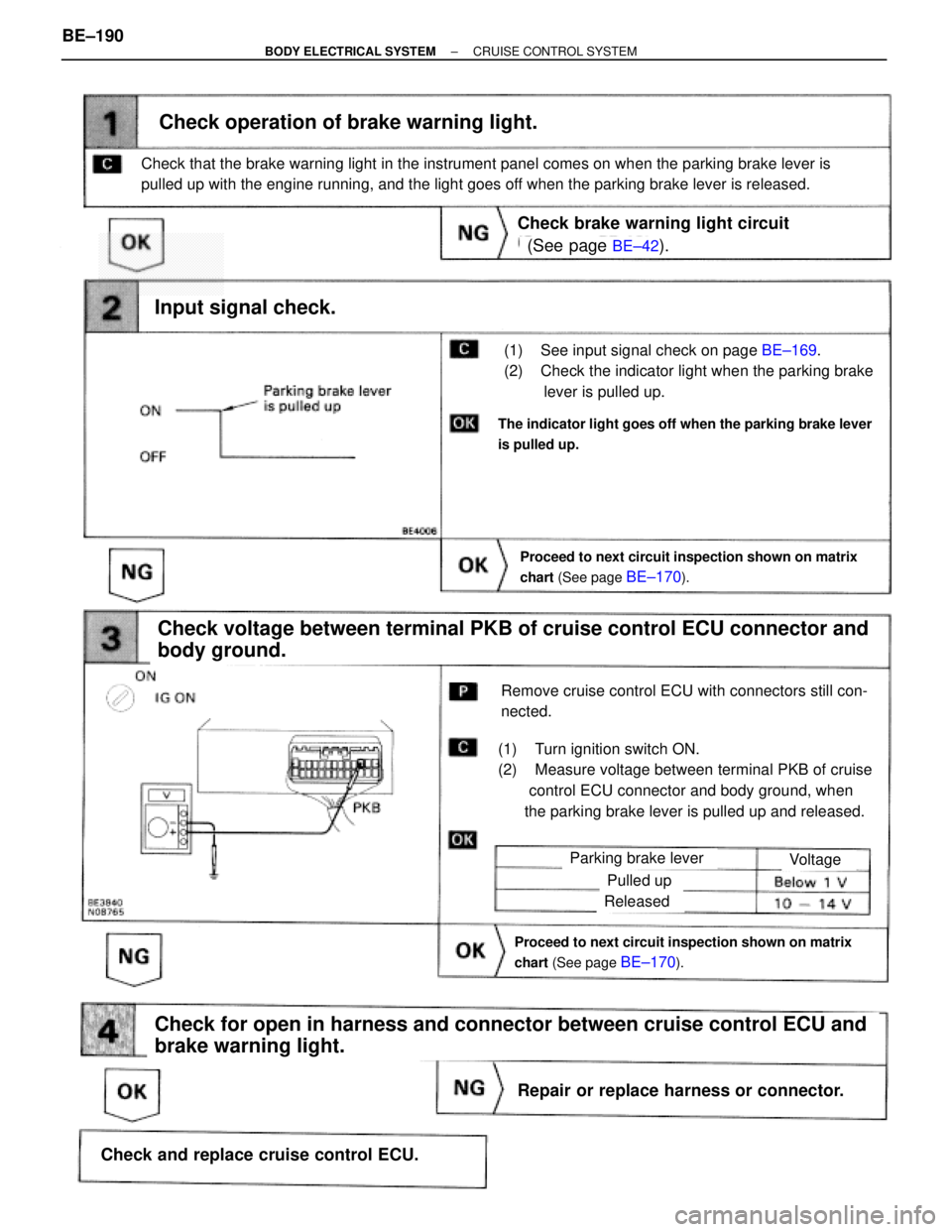
(See page BE±42).
BE±169.
Proceed to next circuit inspection shown on matrix
chart (See page
BE±170).
(1) See input signal check on page BE±169.
(2) Check the indicator light when the parking brake
lever is pulled up.
Check operation of brake warning light.
Check voltage between terminal PKB of cruise control ECU connector and
body ground.
(1) Turn ignition switch ON.
(2) Measure voltage between terminal PKB of cruise
control ECU connector and body ground, when
the parking brake lever is pulled up and released.
Remove cruise control ECU with connectors still con-
nected.
Input signal check.
The indicator light goes off when the parking brake lever
is pulled up.
Check that the brake warning light in the instrument panel comes on when the parking brake lever is
pulled up with the engine running, and the light goes off when the parking brake lever is released.
Check brake warning light circuit
Parking brake lever
Proceed to next circuit inspection shown on matrix
chart (See page
BE±170).
Voltage
Pulled up
Released
Check for open in harness and connector between cruise control ECU and
brake warning light.
Repair or replace harness or connector.
Check and replace cruise control ECU. BE±190
± BODY ELECTRICAL SYSTEMCRUISE CONTROL SYSTEM
Page 875 of 2543
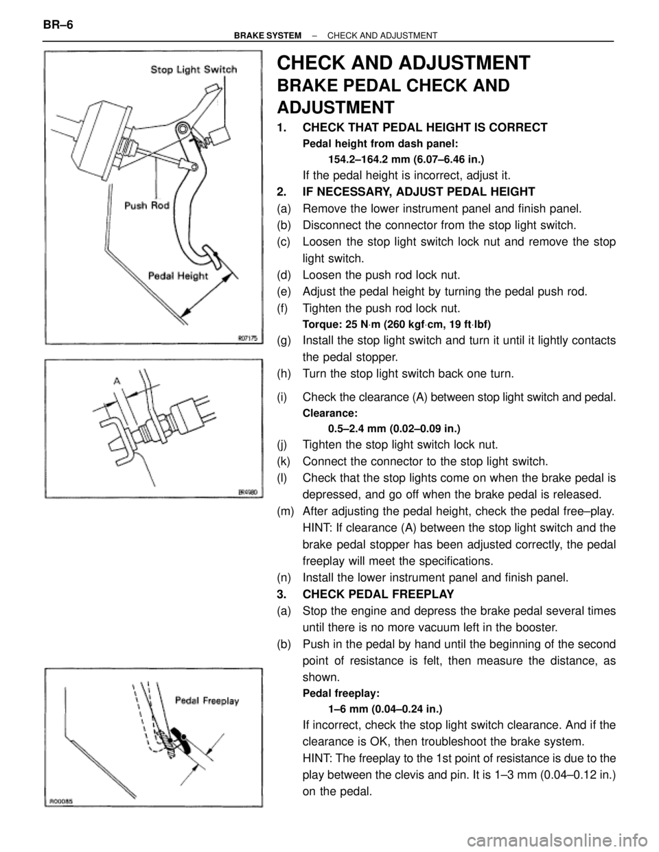
CHECK AND ADJUSTMENT
BRAKE PEDAL CHECK AND
ADJUSTMENT
1. CHECK THAT PEDAL HEIGHT IS CORRECT
Pedal height from dash panel:
154.2±164.2 mm (6.07±6.46 in.)
If the pedal height is incorrect, adjust it.
2. IF NECESSARY, ADJUST PEDAL HEIGHT
(a) Remove the lower instrument panel and finish panel.
(b) Disconnect the connector from the stop light switch.
(c) Loosen the stop light switch lock nut and remove the stop
light switch.
(d) Loosen the push rod lock nut.
(e) Adjust the pedal height by turning the pedal push rod.
(f) Tighten the push rod lock nut.
Torque: 25 NVm (260 kgfVcm, 19 ftVlbf)
(g) Install the stop light switch and turn it until it lightly contacts
the pedal stopper.
(h) Turn the stop light switch back one turn.
(i) Check the clearance (A) between stop light switch and pedal.
Clearance:
0.5±2.4 mm (0.02±0.09 in.)
(j) Tighten the stop light switch lock nut.
(k) Connect the connector to the stop light switch.
(l) Check that the stop lights come on when the brake pedal is
depressed, and go off when the brake pedal is released.
(m) After adjusting the pedal height, check the pedal free±play.
HINT: If clearance (A) between the stop light switch and the
brake pedal stopper has been adjusted correctly, the pedal
freeplay will meet the specifications.
(n) Install the lower instrument panel and finish panel.
3. CHECK PEDAL FREEPLAY
(a) Stop the engine and depress the brake pedal several times
until there is no more vacuum left in the booster.
(b) Push in the pedal by hand until the beginning of the second
point of resistance is felt, then measure the distance, as
shown.
Pedal freeplay:
1±6 mm (0.04±0.24 in.)
If incorrect, check the stop light switch clearance. And if the
clearance is OK, then troubleshoot the brake system.
HINT: The freeplay to the 1st point of resistance is due to the
play between the clevis and pin. It is 1±3 mm (0.04±0.12 in.)
on the pedal. BR±6
± BRAKE SYSTEMCHECK AND ADJUSTMENT
Page 876 of 2543
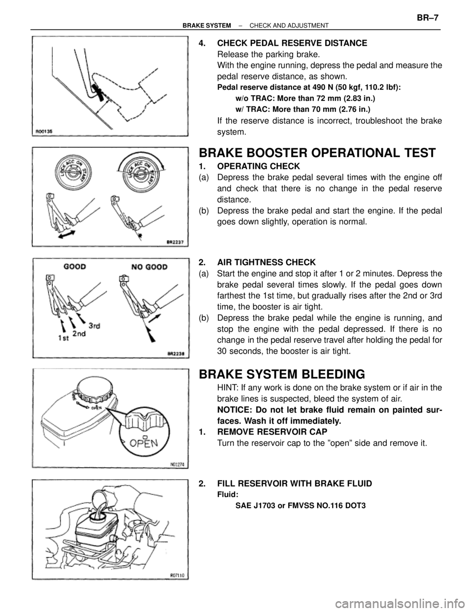
4. CHECK PEDAL RESERVE DISTANCE
Release the parking brake.
With the engine running, depress the pedal and measure the
pedal reserve distance, as shown.
Pedal reserve distance at 490 N (50 kgf, 110.2 lbf):
w/o TRAC: More than 72 mm (2.83 in.)
w/ TRAC: More than 70 mm (2.76 in.)
If the reserve distance is incorrect, troubleshoot the brake
system.
BRAKE BOOSTER OPERATIONAL TEST
1. OPERATING CHECK
(a) Depress the brake pedal several times with the engine off
and check that there is no change in the pedal reserve
distance.
(b) Depress the brake pedal and start the engine. If the pedal
goes down slightly, operation is normal.
2. AIR TIGHTNESS CHECK
(a) Start the engine and stop it after 1 or 2 minutes. Depress the
brake pedal several times slowly. If the pedal goes down
farthest the 1st time, but gradually rises after the 2nd or 3rd
time, the booster is air tight.
(b) Depress the brake pedal while the engine is running, and
stop the engine with the pedal depressed. If there is no
change in the pedal reserve travel after holding the pedal for
30 seconds, the booster is air tight.
BRAKE SYSTEM BLEEDING
HINT: If any work is done on the brake system or if air in the
brake lines is suspected, bleed the system of air.
NOTICE: Do not let brake fluid remain on painted sur-
faces. Wash it off immediately.
1. REMOVE RESERVOIR CAP
Turn the reservoir cap to the ºopenº side and remove it.
2. FILL RESERVOIR WITH BRAKE FLUID
Fluid:
SAE J1703 or FMVSS NO.116 DOT3
± BRAKE SYSTEMCHECK AND ADJUSTMENTBR±7
Page 882 of 2543
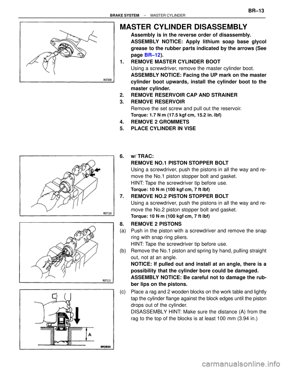
MASTER CYLINDER DISASSEMBLY
Assembly is in the reverse order of disassembly.
ASSEMBLY NOTICE: Apply lithium soap base glycol
grease to the rubber parts indicated by the arrows (See
page BR±12).
1. REMOVE MASTER CYLINDER BOOT
Using a screwdriver, remove the master cylinder boot.
ASSEMBLY NOTICE: Facing the UP mark on the master
cylinder boot upwards, install the cylinder boot to the
master cylinder.
2. REMOVE RESERVOIR CAP AND STRAINER
3. REMOVE RESERVOIR
Remove the set screw and pull out the reservoir.
Torque: 1.7 NVm (17.5 kgfVcm, 15.2 in.Vlbf)
4. REMOVE 2 GROMMETS
5. PLACE CYLINDER IN VISE
6. w/ TRAC:
REMOVE NO.1 PISTON STOPPER BOLT
Using a screwdriver, push the pistons in all the way and re-
move the No.1 piston stopper bolt and gasket.
HINT: Tape the screwdriver tip before use.
Torque: 10 NVm (100 kgfVcm, 7 ftVlbf)
7. REMOVE NO.2 PISTON STOPPER BOLT
Using a screwdriver, push the pistons in all the way and re-
move the No.2 piston stopper bolt and gasket.
Torque: 10 NVm (100 kgfVcm, 7 ftVlbf)
8. REMOVE 2 PISTONS
(a) Push in the piston with a screwdriver and remove the snap
ring with snap ring pliers.
HINT: Tape the screwdriver tip before use.
(b) Remove the No.1 piston and spring by hand, pulling straight
out, not at an angle.
NOTICE: If pulled out and install at an angle, there is a
possibility that the cylinder bore could be damaged.
ASSEMBLY NOTICE: Be careful not to damage the rub-
ber lips on the pistons.
(c) Place a rag and 2 wooden blocks on the work table and lightly
tap the cylinder flange against the block edges until the piston
drops out of the cylinder.
DISASSEMBLY HINT: Make sure the distance (A) from the
rag to the top of the blocks is at least 100 mm (3.94 in.)
± BRAKE SYSTEMMASTER CYLINDERBR±13
Page 885 of 2543
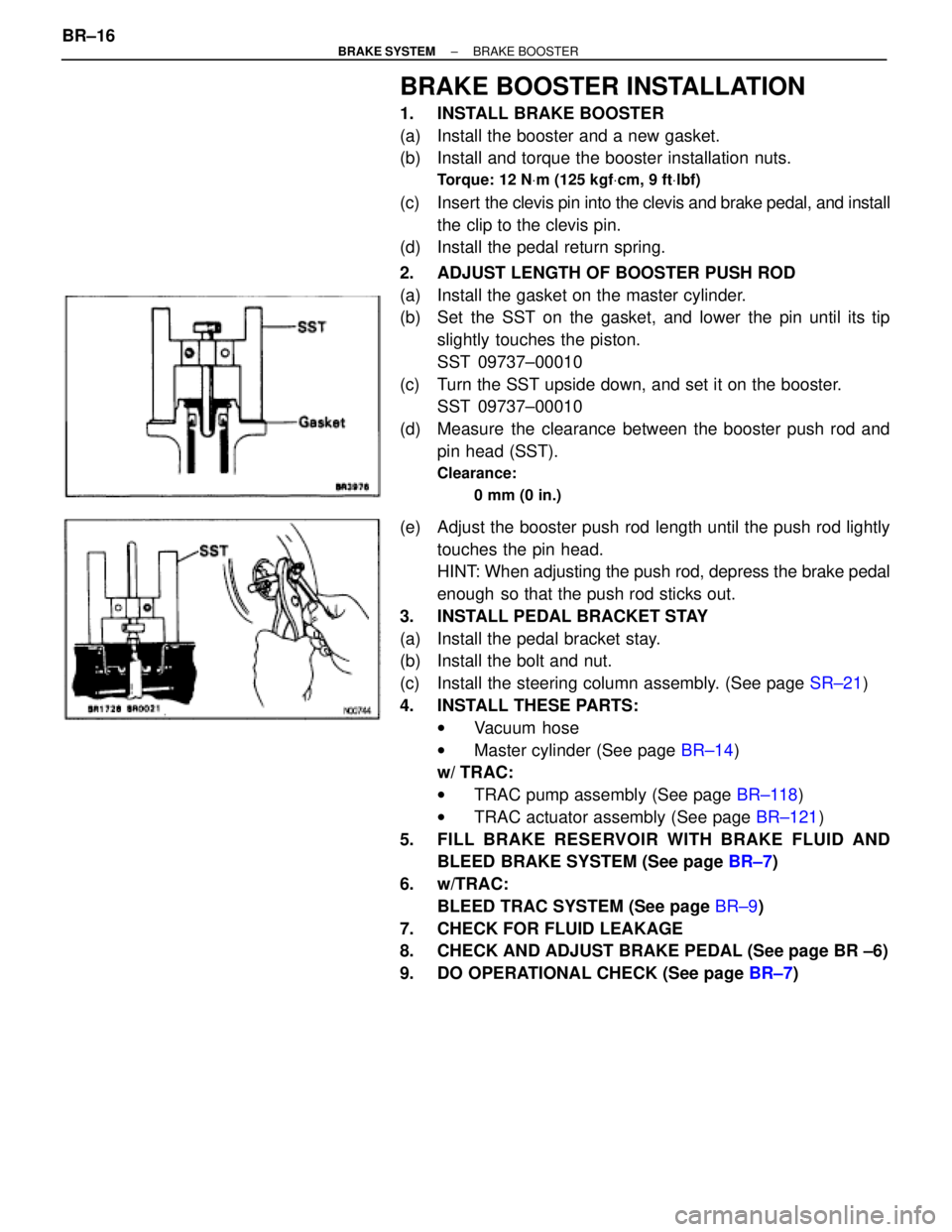
BRAKE BOOSTER INSTALLATION
1. INSTALL BRAKE BOOSTER
(a) Install the booster and a new gasket.
(b) Install and torque the booster installation nuts.
Torque: 12 NVm (125 kgfVcm, 9 ftVlbf)
(c) Insert the clevis pin into the clevis and brake pedal, and install
the clip to the clevis pin.
(d) Install the pedal return spring.
2. ADJUST LENGTH OF BOOSTER PUSH ROD
(a) Install the gasket on the master cylinder.
(b) Set the SST on the gasket, and lower the pin until its tip
slightly touches the piston.
SST 09737±00010
(c) Turn the SST upside down, and set it on the booster.
SST 09737±00010
(d) Measure the clearance between the booster push rod and
pin head (SST).
Clearance:
0 mm (0 in.)
(e) Adjust the booster push rod length until the push rod lightly
touches the pin head.
HINT: When adjusting the push rod, depress the brake pedal
enough so that the push rod sticks out.
3. INSTALL PEDAL BRACKET STAY
(a) Install the pedal bracket stay.
(b) Install the bolt and nut.
(c) Install the steering column assembly. (See page SR±21)
4. INSTALL THESE PARTS:
wVacuum hose
wMaster cylinder (See page BR±14)
w/ TRAC:
wTRAC pump assembly (See page BR±118)
wTRAC actuator assembly (See page BR±121)
5. FILL BRAKE RESERVOIR WITH BRAKE FLUID AND
BLEED BRAKE SYSTEM (See page BR±7)
6. w/TRAC:
BLEED TRAC SYSTEM (See page BR±9)
7. CHECK FOR FLUID LEAKAGE
8. CHECK AND ADJUST BRAKE PEDAL (See page BR ±6)
9. DO OPERATIONAL CHECK (See page BR±7) BR±16
± BRAKE SYSTEMBRAKE BOOSTER
Page 923 of 2543
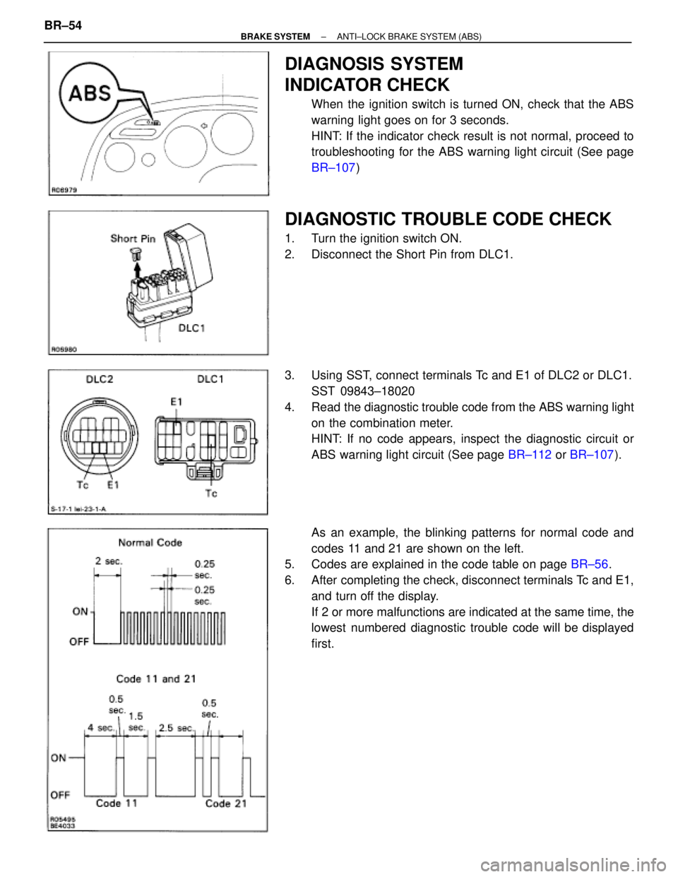
DIAGNOSIS SYSTEM
INDICATOR CHECK
When the ignition switch is turned ON, check that the ABS
warning light goes on for 3 seconds.
HINT: If the indicator check result is not normal, proceed to
troubleshooting for the ABS warning light circuit (See page
BR±107)
DIAGNOSTIC TROUBLE CODE CHECK
1. Turn the ignition switch ON.
2. Disconnect the Short Pin from DLC1.
3. Using SST, connect terminals Tc and E1 of DLC2 or DLC1.
SST 09843±18020
4. Read the diagnostic trouble code from the ABS warning light
on the combination meter.
HINT: If no code appears, inspect the diagnostic circuit or
ABS warning light circuit (See page BR±112 or BR±107).
As an example, the blinking patterns for normal code and
codes 11 and 21 are shown on the left.
5. Codes are explained in the code table on page BR±56.
6. After completing the check, disconnect terminals Tc and E1,
and turn off the display.
If 2 or more malfunctions are indicated at the same time, the
lowest numbered diagnostic trouble code will be displayed
first. BR±54
± BRAKE SYSTEMANTI±LOCK BRAKE SYSTEM (ABS)
Page 924 of 2543
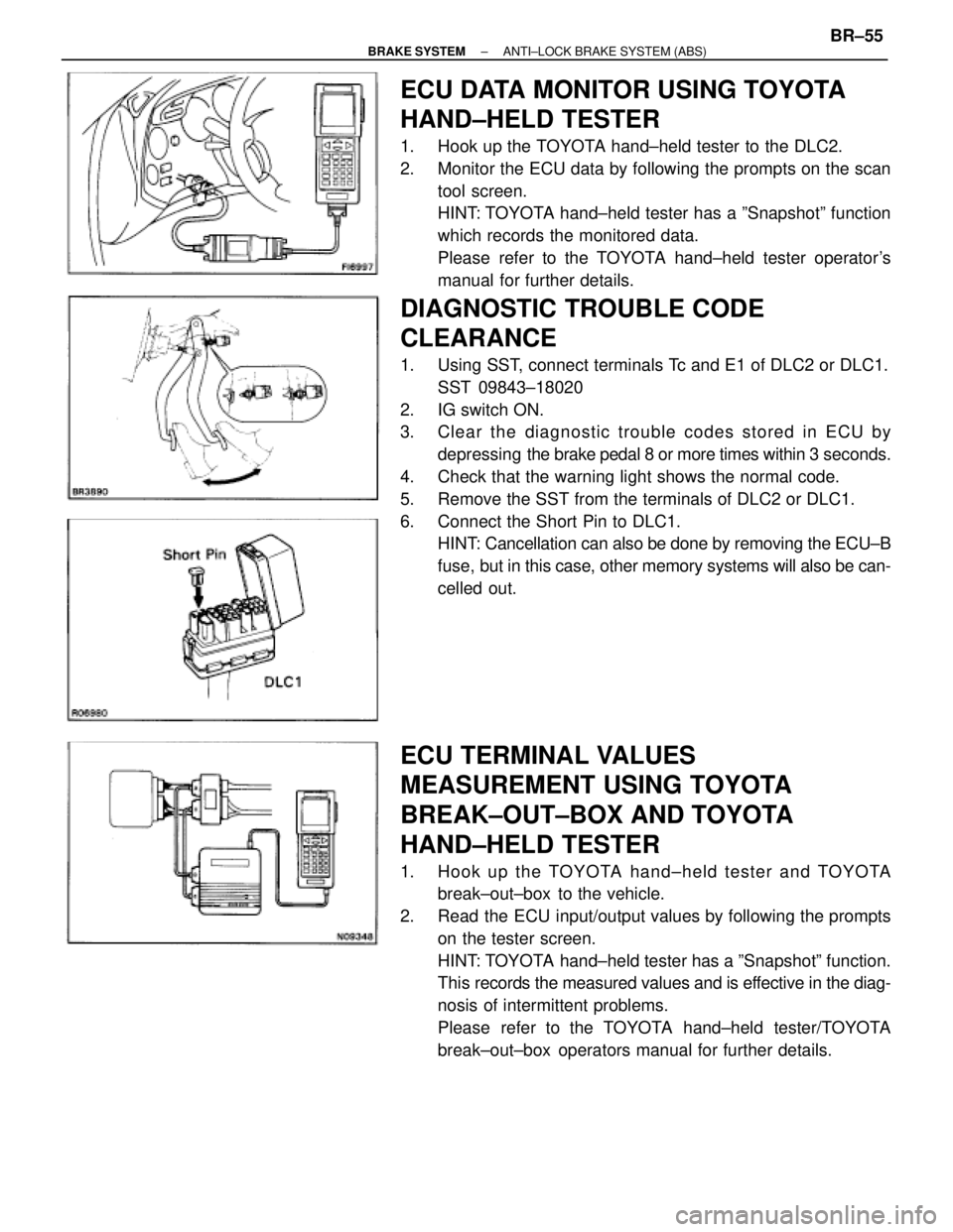
ECU DATA MONITOR USING TOYOTA
HAND±HELD TESTER
1. Hook up the TOYOTA hand±held tester to the DLC2.
2. Monitor the ECU data by following the prompts on the scan
tool screen.
HINT: TOYOTA hand±held tester has a ºSnapshotº function
which records the monitored data.
Please refer to the TOYOTA hand±held tester operator's
manual for further details.
DIAGNOSTIC TROUBLE CODE
CLEARANCE
1. Using SST, connect terminals Tc and E1 of DLC2 or DLC1.
SST 09843±18020
2. IG switch ON.
3. Clear the diagnostic trouble codes stored in ECU by
depressing the brake pedal 8 or more times within 3 seconds.
4. Check that the warning light shows the normal code.
5. Remove the SST from the terminals of DLC2 or DLC1.
6. Connect the Short Pin to DLC1.
HINT: Cancellation can also be done by removing the ECU±B
fuse, but in this case, other memory systems will also be can-
celled out.
ECU TERMINAL VALUES
MEASUREMENT USING TOYOTA
BREAK±OUT±BOX AND TOYOTA
HAND±HELD TESTER
1. Hook up the TOYOTA hand±held tester and TOYOTA
break±out±box to the vehicle.
2. Read the ECU input/output values by following the prompts
on the tester screen.
HINT: TOYOTA hand±held tester has a ºSnapshotº function.
This records the measured values and is effective in the diag-
nosis of intermittent problems.
Please refer to the TOYOTA hand±held tester/TOYOTA
break±out±box operators manual for further details.
± BRAKE SYSTEMANTI±LOCK BRAKE SYSTEM (ABS)BR±55
Page 925 of 2543
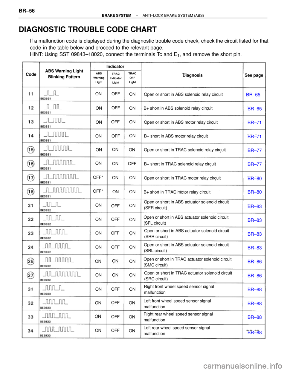
DIAGNOSTIC TROUBLE CODE CHART
If a malfunction code is displayed during the diagnostic trouble code check, check the circuit listed for that
code in the table below and proceed to the relevant page.
HINT: Using SST 09843±18020, connect the terminals Tc and E
1, and remove the short pin.
BR±65
BR±65
BR±71
BR±71
BR±77
BR±77
BR±80
BR±80
BR±83
BR±83
BR±83
BR±83
BR±86
BR±86
BR±88
BR±88
BR±88
BR±88
ON
ON
ON
ON
ON
ON
ON
ON
ON
ON
ON
ON
ON
ON
ON
ON
ON
ON
ON
ON
ON
ON
ON
ON
ON
ON
ON
ON
ON
ON
ON
ON
ON
ON
ON
ON
ON
ON
ON
OFF
OFF
OFF
OFF
OFF
OFF
OFF
OFF
OFF
OFF
OFF
OFF
OFF
OFF*
OFF*
CodeABS Warning Light
Blinking PatternIndicator
DiagnosisSee pageABS
Warning
LightTRAC
OFF
LightTRAC
Indicator
Light
Open or short in ABS solenoid relay circuit
B+ short in ABS solenoid relay circuit
Open or short in ABS motor relay circuit
B+ short in ABS motor relay circuit
Open or short in TRAC solenoid relay circuit
B+ short in TRAC solenoid relay circuit
Open or short in TRAC motor relay circuit
B+ short in TRAC motor relay circuit
Open or short in ABS actuator solenoid circuit
(SFR circuit)
Open or short in ABS actuator solenoid circuit
(SFL circuit)
Open or short in ABS actuator solenoid circuit
(SRR circuit)
Open or short in ABS actuator solenoid circuit
(SRL circuit)
Open or short in TRAC actuator solenoid circuit
(SMC circuit)
Open or short in TRAC actuator solenoid circuit
(SRC circuit)
Right front wheel speed sensor signal
malfunction
Left front wheel speed sensor signal
malfunction
Right rear wheel speed sensor signal
malfunction
Left rear wheel speed sensor signal
malfunction
BR±56± BRAKE SYSTEMANTI±LOCK BRAKE SYSTEM (ABS)