Page 98 of 2248
TROUBLE
Engine will not start.
Rough idle and engine stall
Low output, hesitation and poor acceleration
Surging
Engine does not return to idle.
Dieseling (Run-on)
After burning in exhaust system
Knocking
Excessive engine oil consumption
Excessive fuel consumption Starter does not turn.
Initial combustion does not occur.
Initial combustion occurs.
Engine stalls after initial combustion.
LUBRICATION SYSTEM
22 3 3�Incorrect oil pressure
2�Loosened oil pump attaching bolts and defective
gasket
2�Defective oil filter seal
2�Defective crankshaft oil seal
32�Defective rocker cover gasket
2�Loosened oil drain plug or defective gasket
2�Loosened oil pan fitting bolts or defective oil pan
COOLING SYSTEM
33221�Overheating
333�Over cooling
OTHERS
113 3�Malfunction of Evaporative Emission Control
System
21�Stuck or damaged throttle valve
322 2�Accelerator cable out of adjustment
77
2-3DIAGNOSTICS
1. Engine Trouble in General
Page 99 of 2248

2. Engine Noise
Valve lash adjusters may make clicking noise once engine
starts. It is normal if clicking noise ceases after a few min-
utes.
If clicking noise continues after a few minutes, check
engine oil level and add oil if necessary.
Then, do as follows to cease clicking noise.
1) Warm-up engine for five minutes.
2) Turn ignition switch OFF.
3) Connect test mode connector.
4) Start the engine and run it at approximately 2,000 rpm
for twenty minutes.
5) Turn ignition switch OFF.
6) Disconnect test mode connector.
7) Start the engine and check that clicking noise is ceased.
If noise still exists, conduct troubleshooting procedures in
accordance with the following table.
CAUTION:
Do not disconnect spark plug cord while engine is run-
ning.
Type of sound Condition Possible cause
Regular clicking soundSound increases as engine
speed increases.Valve mechanism is defective.
�Broken lash adjuster
�Worn valve rocker
�Worn camshaft
�Broken valve spring
�Worn valve lifter hole
Heavy and dull clankOil pressure is low.�Worn crankshaft main bearing
�Worn connecting rod bearing (big end)
Oil pressure is normal.�Loose flywheel mounting bolts
�Damaged engine mounting
High-pitched clank
(Spark knock)Sound is noticeable when
accelerating with an overload.�Ignition timing advanced
�Accumulation of carbon inside combustion chamber
�Wrong spark plug
�Improper gasoline
Clank when engine speed is
medium (1,000 to 2,000 rpm).Sound is reduced when fuel
injector connector of noisy
cylinder is disconnected.
(NOTE*)�Worn crankshaft main bearing
�Worn bearing at crankshaft end of connecting rod
Knocking sound when engine
is operating under idling speed
and engine is warm.Sound is reduced when fuel
injector connector of noisy
cylinder is disconnected.
(NOTE*)�Worn cylinder liner and piston ring
�Broken or stuck piston ring
�Worn piston pin and hole at piston end of connecting rod
Sound is not reduced if each
fuel injector connector is
disconnected in turn. (NOTE*)�Unusually worn valve lifter
�Worn cam gear
�Worn camshaft journal bore in crankcase
Squeaky sound—�Insufficient generator lubrication
Rubbing sound—�Defective generator brush and rotor contact
Gear scream when starting
engine—�Defective ignition starter switch
�Worn gear and starter pinion
Sound like polishing glass with
a dry cloth—�Loose drive belt
�Defective engine coolant pump shaft
78
2-3DIAGNOSTICS
2. Engine Noise
Page 100 of 2248
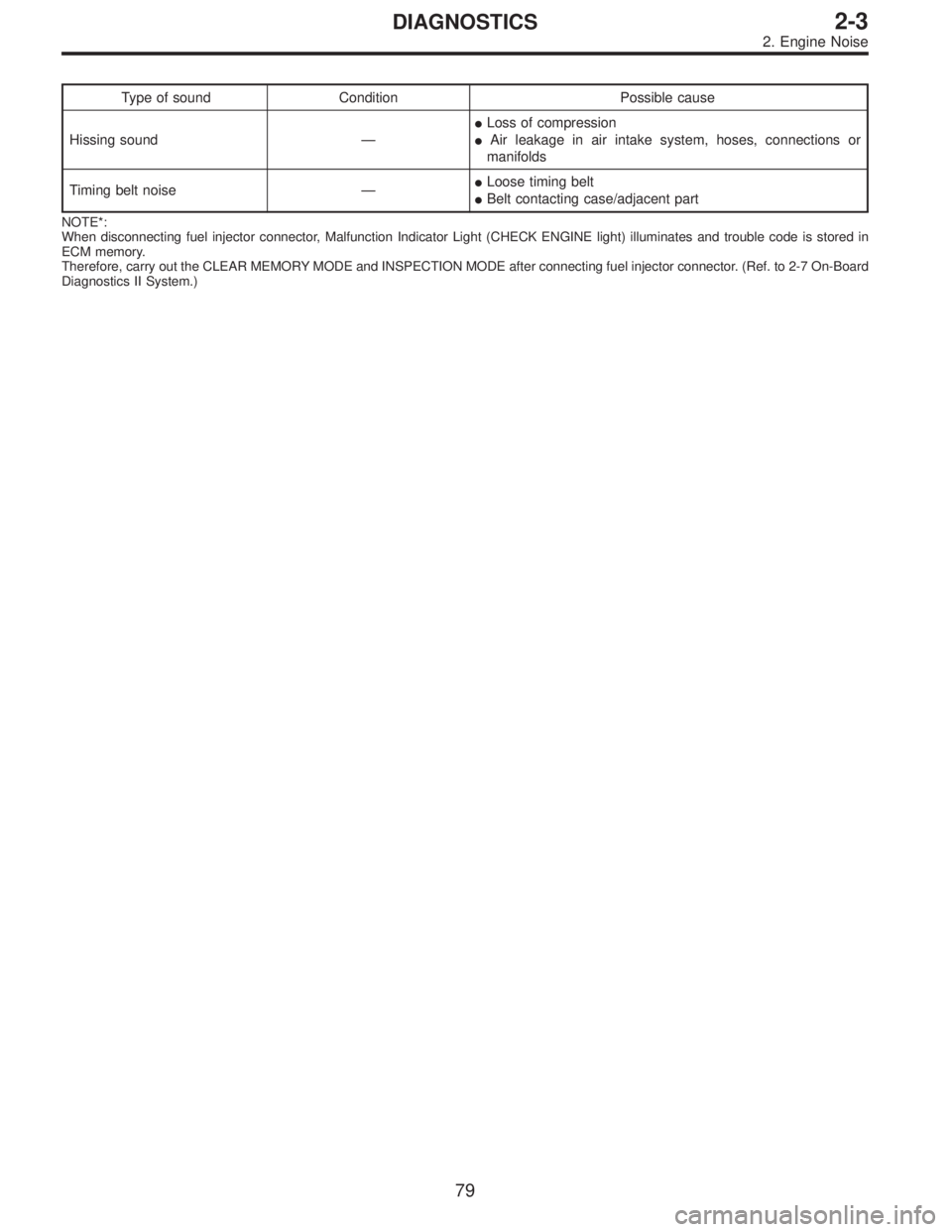
Type of sound Condition Possible cause
Hissing sound—�Loss of compression
�Air leakage in air intake system, hoses, connections or
manifolds
Timing belt noise—�Loose timing belt
�Belt contacting case/adjacent part
NOTE*:
When disconnecting fuel injector connector, Malfunction Indicator Light (CHECK ENGINE light) illuminates and trouble code is stored in
ECM memory.
Therefore, carry out the CLEAR MEMORY MODE and INSPECTION MODE after connecting fuel injector connector. (Ref. to 2-7 On-Board
Diagnostics II System.)
79
2-3DIAGNOSTICS
2. Engine Noise
Page 101 of 2248

1. Lubrication System
A: SPECIFICATIONS
Lubrication methodForced lubrication
Oil pumpPump typeTrochoid type
Number of teethInner rotor 9
Outer rotor 10
Outer rotor diameter x thickness 78x9mm(3.07 x 0.35 in)
Tip clearance between inner and outer rotorSTANDARD 0.04 — 0.14 mm (0.0016 — 0.0055 in)
LIMIT 0.18 mm (0.0071 in)
Side clearance between inner rotor and pump
caseSTANDARD 0.02 — 0.07 mm (0.0008 — 0.0028 in)
LIMIT 0.15 mm (0.0059 in)
Case clearance between outer rotor and pump
caseSTANDARD 0.10 — 0.175 mm (0.0039 — 0.0069 in)
LIMIT 0.20 mm (0.0079 in)
Capacity at
80°C (176°F)700 rpm Discharge- pressure 98 kPa (1.0 kg/cm
2, 14 psi) or more
- quantity 4.2�(4.4 US qt, 3.7 Imp qt)/min.
5,000 rpm Discharge- pressure 294 kPa (3.0 kg/cm
2, 43 psi) or more
- quantity 42.0�(11.10 US gal, 9.24 Imp gal)/min.
Relief valve operation pressure 490 kPa (5.0 kg/cm
2, 71 psi)
Oil filterTypeFull-flow filter type
Filtration area 1,000 cm
2(155 sq in)
By-pass valve opening pressure 157 kPa (1.6 kg/cm
2, 23 psi)
Outer diameter x width 80 x 70 mm (3.15 x 2.76 in)
Oil filter to engine thread size M 20 x 1.5
Relief valve (on rocker shaft) operation pressure 69 kPa (0.7kg/cm
2, 10 psi)
Oil pressure
switchTypeImmersed contact point type
Working voltage — wattage 12 V — 3.4 W or less
Warning light activation pressure 14.7 kPa (0.15 kg/cm
2, 2.1 psi)
Proof pressure More than 981 kPa (10 kg/cm
2, 142 psi)
Oil pan capacity4.0�(4.2 US qt, 3.5 Imp qt)
2
2-4SPECIFICATIONS AND SERVICE DATA
1. Lubrication System
Page 103 of 2248
G2M0066
1. Oil Pump
A: REMOVAL
1) Drain engine oil.
Set container under the vehicle, and remove drain plug
from oil pan.
B2M0051A
2) Drain coolant.
Set container under the vehicle, and remove drain cock
from radiator.
B2M0302
3) Remove belt covers, timing belt and related parts.
B2M0303
4) Remove belt tensioner bracket.
G2M0210
5) Remove left cam sprocket and left belt cover No. 2.
6) Remove water pump.
4
2-4SERVICE PROCEDURE
1. Oil Pump
Page 107 of 2248
G2M0544
2. Oil Pan and Oil Strainer
A: REMOVAL
1) Remove front wheels.
2) Remove air intake duct.
3) Disconnect connector from front oxygen sensor.
G2M0295
4) Remove pitching stopper.
B2M0320
5) Remove radiator upper brackets.
B2M0053
6) Support engine with a lifting device and wire ropes.
7) Lift-up the vehicle.
CAUTION:
At this time, raise up wire ropes.
G2M0066
8) Drain engine oil.
Set container under the vehicle, and remove drain plug
from oil pan.
8
2-4SERVICE PROCEDURE
2. Oil Pan and Oil Strainer
Page 108 of 2248
B2M0312
9) Disconnect connector from rear oxygen sensor.
B2M0054
10) Remove front exhaust pipe.
(1) Separate front catalytic converter from center
exhaust pipe.
(2) Remove front exhaust pipe from engine.
(3) Remove bolt which installs front exhaust pipe on
bracket.
G2M0293
11) Remove nuts which install front cushion rubber onto
front crossmember.
G2M0081
12) Remove bolts which install oil pan on cylinder block
while raising up engine.
13) Insert oil pan cutter blade between cylinder block-to-oil
pan clearance.
CAUTION:
Do not use a screwdriver or similar tool in place of oil
pan cutter.
G2M0082
14) Separate oil strainer from oil strainer stay.
9
2-4SERVICE PROCEDURE
2. Oil Pan and Oil Strainer
Page 109 of 2248
G2M0376
15) Remove oil strainer.
G2M0377
16) Remove baffle plate and oil strainer stay.
B: INSPECTION
By visual check make sure oil pan, oil strainer, oil strainer
stay and baffle plate are not damaged.
G2M0377
C: INSTALLATION
CAUTION:
Before installing oil pan, clean sealant from oil and
engine block.
1) Install baffle plate and oil strainer stay.
Tightening torque:
5N⋅m (0.5 kg-m, 3.6 ft-lb)
G2M0376
2) Install oil strainer onto baffle plate.
CAUTION:
Replace O-ring with a new one.
Tightening torque:
9.8 N⋅m (1.0 kg-m, 7 ft-lb)
10
2-4SERVICE PROCEDURE
2. Oil Pan and Oil Strainer

After burning in exhaust system
Knock")
 Drain engine oil.
Set container under the vehicle, and remove drain plug
from oil pan.
B2M0051A
2) Drain coolant.
Set container under the vehicle, and remove drain co")
 Remove front wheels.
2) Remove air intake duct.
3) Disconnect connector from front oxygen sensor.
G2M0295
4) Remove pitching stopper.
B2M0320
5) Remov")
 Disconnect connector from rear oxygen sensor.
B2M0054
10) Remove front exhaust pipe.
(1) Separate front catalytic converter from center
exhaust pipe.
(2) Remove front exhaust pipe from engi")
 Remove oil strainer.
G2M0377
16) Remove baffle plate and oil strainer stay.
B: INSPECTION
By visual check make sure oil pan, oil strainer, oil strainer
stay and baffle plate are not damage")