Page 2191 of 2248
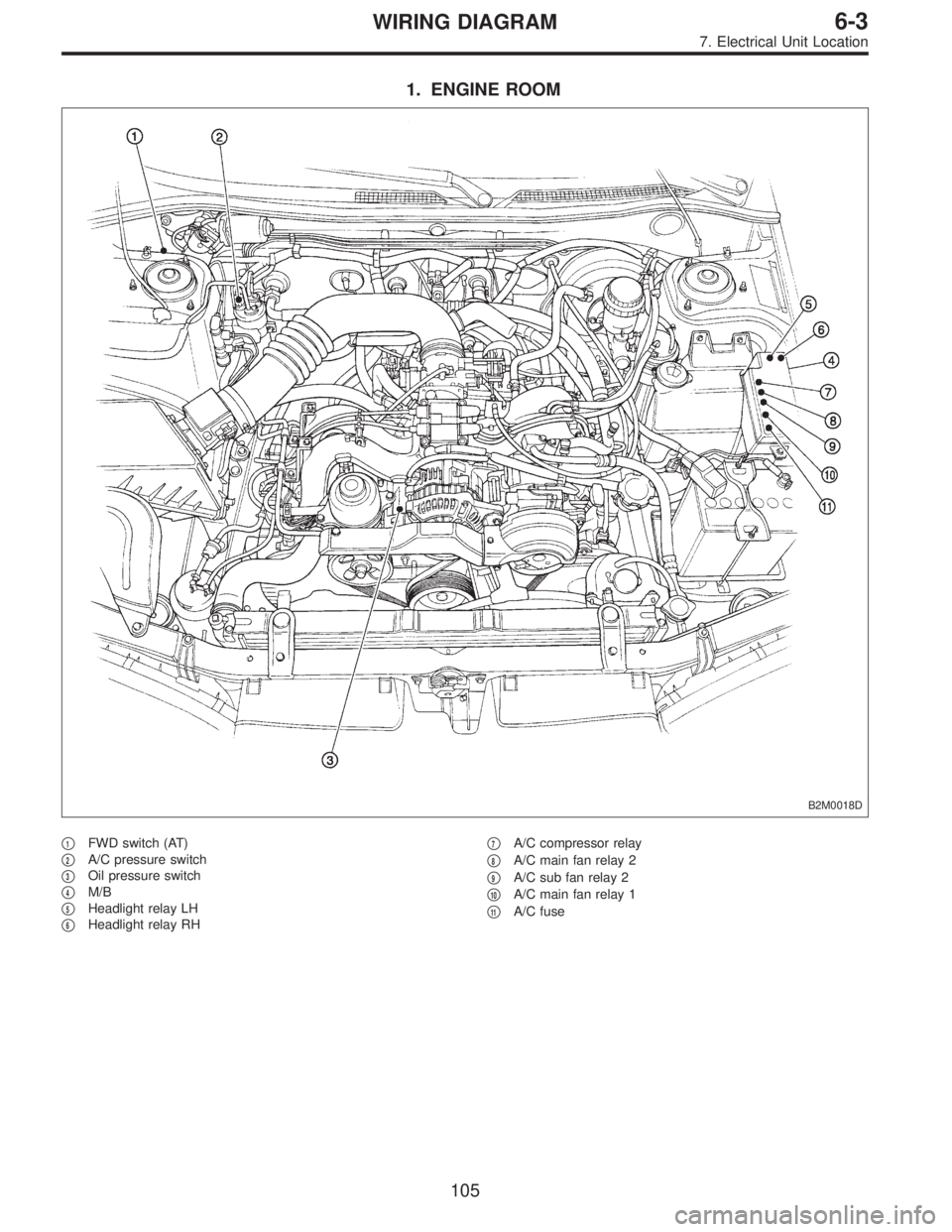
1. ENGINE ROOM
B2M0018D
�1FWD switch (AT)
�
2A/C pressure switch
�
3Oil pressure switch
�
4M/B
�
5Headlight relay LH
�
6Headlight relay RH�
7A/C compressor relay
�
8A/C main fan relay 2
�
9A/C sub fan relay 2
�
10A/C main fan relay 1
�
11A/C fuse
105
6-3WIRING DIAGRAM
7. Electrical Unit Location
Page 2204 of 2248

Connector Connecting to
No. Pole Color Area No. Name
E1 6 * A-3 B20
Bulkhead wiring harness E2 12 Gray A-3 B21
E3 16 Gray A-3 B22
E4 2 Blue A-2 Purge control solenoid valve
E5 2 Light gray A-2 Injector #1
E6 2 Dark gray A-3 Injector #3
E7 3 Gray A-3 Idle air control solenoid valve
E8 2 Brown B-3 Engine coolant temperature sensor
E9 1 * B-3 Thermometer
E10 2 Gray B-3 Crankshaft position sensor
E11 1 * B-3 Oil pressure switch
E12 3 Gray A-3 Ignition coil
E13 3 Brown A-3 Throttle position sensor
E14 1 Gray B-3 Knock sensor
E15 2 Dark gray B-4 Camshaft position sensor
E16 2 Light gray B-4 Injector #2
E17 2 Dark gray B-4 Injector #4
E18 2 Brown B-3 EGR solenoid (AT)
*: Non-colored
Connector Connecting to
No. Pole Color Area No. Name
T1 2 Gray C-1 B24
Bulkhead wiring harness (MT)
T2 2 Brown C-1 B25
T3 12 Gray D-3 B12
Bulkhead wiring harness (AT)
T4 16 Gray D-3 B11
T5 4 Gray C-1/C-3 B19 Bulkhead wiring harness
T6 4 Gray D-2/D-4 Rear oxygen sensor
11 8
6-3WIRING DIAGRAM
8. Electrical Wiring Harness and Ground Point
Page 2230 of 2248

How to use this manual
�This Service Manual is divided into four volumes by section so that it can be used with ease at work. Refer to
the Table of Contents, select and use the necessary section.
�GENERAL INFORMATION SECTION
�REPAIR SECTION
�TROUBLESHOOTING SECTION
�WIRING DIAGRAM SECTION
�Each chapter in the manual is basically made of the following four types of areas.
S SPECIFICATIONS AND SERVICE DATA
C COMPONENT PARTS
W SERVICE PROCEDURE
(X SERVICE PROCEDURE)
(Y SERVICE PROCEDURE)
K DIAGNOSTICS
�The description of each area is provided with four types of titles different in size as shown below. The Title No.
or Symbol prefixes each title in order that the construction of the article and the flow of explanation can be eas-
ily understood.
[Example of each title]
�Area title: W SERVICE PROCEDURE (one of the four types of areas)
�Large title (Heading): 1. Oil Pump (to denote the main item of explanation)
�Medium title (Section): A: REMOVAL (to denote the type of work in principle)
�Small title (Sub-section): 1. INNER ROTATOR (to denote a derivative item of explanation)
3
Page 2232 of 2248

�In this manual, the following symbols are used.
*: Selective part
�: Replacement part
: Should be lubricated with oil.
: Should be lubricated with grease.
: Sealing point
: Tightening torque
�WARNING, CAUTION, NOTE
�WARNING: Indicates the item which must be observed precisely during performance of maintenance ser-
vices in order to avoid injury to the mechanics and other persons.
�CAUTION: Indicates the item which must be followed precisely during performance of maintenance ser-
vices so as to avoid damage and breakage to the vehicle and its parts and components.
�NOTE: Indicates the hints, knacks, etc. which make the maintenance job easier.
�SPECIAL TOOLS
When any special tool is required to perform the job, it is identified by“ST”in the applicable illustration and its
part number is shown in the manual.
M1H0120
1. Procedures for adjusting backlash
1) Set steering wheel to the straight-ahead position.
2) Remove the exhaust pipe
3) Loosen the lock nut with ST.
�
{ST1 921650000 STEERING GEARBOX WRENCH
ST2 921550000 STEERING GEARBOX WRENCH
Description
(of job method)
Shows the part name
Shows the part number
Tells that two kinds of special tools are required.
When two or more kinds of special tools are required to do
a job, they are identified by ST1, ST2,......respectively.
�
��
5