Page 1694 of 1701

POWERSTEERING GEARANDLINKAGE (ModelPR24AC)
Adjustment (Cont'd)
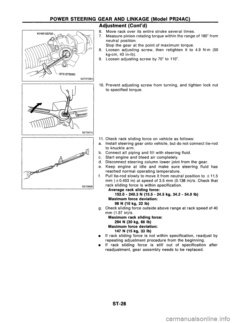
6. Move rackover itsentire stroke several times.
7. Measure pinionrotating torquewithintherange of180° from
neutral position.
Stop thegear atthe point ofmaximum torque.
8. Loosen adjusting screw,thenretighten itto 4.9 N'm (50
kg-em, 43in-Ib).
9. Loosen adjusting screwby70° to110°.
SST072BA
10.Prevent adjusting screwfromturning, andtighten locknut
to specified torque.
SST557A
SST090B
11.
Check racksliding forceonvehicle asfollows:
a. Install steering gearontovehicle, butdonot connect tie-rod
to knuckle arm.
b. Connect allpiping andfillwith steering fluid.
c. Start engine andbleed aircompletely.
d. Disconnect steeringcolumnlowerjointfrom thegear.
e. Keep engine atidle and make suresteering fluidhas
reached normaloperating temperature.
f. Pull tie-rod slowlytomove itfrom neutral position to
:l:
11.5
mm
(:l:
0.453 in)atspeed of3.5 mm (0.138 in)/s.Check that
rack sliding forceiswithin specification.
Average racksliding force:
152.0 -240.3 N(15.5 .24.5 kg,34.2.54.0 Ib)
Maximum forcedeviation:
98 N(10 kg,22Ib)
g. Check sliding forceoutside aboverangeatrack speed of40
mm (1.57 in)/s.
Maximum racksliding force:
294 N(30 kg, 66Ib)
Maximum forcedeviation:
147 N(15 kg, 33Ib)
• Ifrack sliding forceisnot within specification, readjustby
repeating adjustment procedurefromthebeginning.
• If
rack sliding forceisstill outofspecification after
readjustment, gearassembly needstobe replaced.
ST-28
Page 1695 of 1701

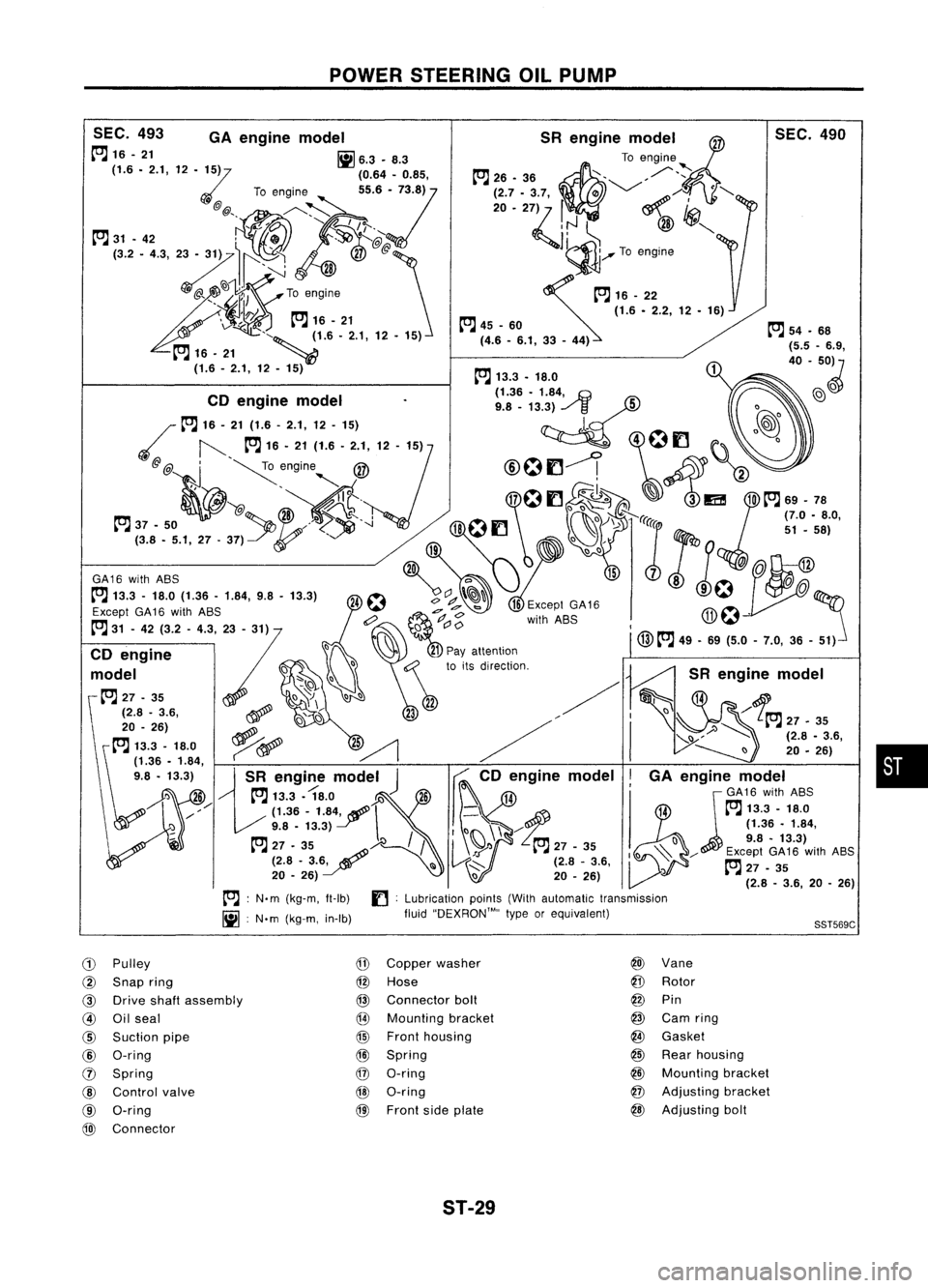
POWERSTEERING OILPUMP
•
SST569C
SEC.
490
SR engine model~
To engine
~26. 36~ ,/"~
;~7 ..
':ij m '-/
~/i<> ·"-
~':J ~
@
'CJ!I",
1~ ........To engine
~16_22 (1.6•2.2, 12•16)
~ 45-60
(4.6 -6.1, 33-44)
SEC.
493 GAengine model
~16-21 [ij6.3.8.3
(1.6. 2.1,12
'Z5)
(0.64.0.85,
To engine
55.6:/73.8)
@ @" ./'----~
, "I
/e;..
~ 31•42 ',.., 0
.'$>J
K@
J:
<~~~iX':I~
Toengine
\1f!.7~
Pm
16-21
v. ~-..
, "~ ~1.6'2.1,12•15)
~ 16. 21 _~
(1.6 -2.1, 12. 15) ~
54.68
{5.5 -6.9,
40 -50~
~ 13.3. 18.0
. (1.36•1.84,
.G
@)
0
CD engine model
9.8_13.3) ../
/3
5
0
~ 16-21 (1.6 -2.1, 12-15)
l.~
@@ ,
~engine @
@Of1--! ~
2
" ," I~
.' "@
It. 17
0
f1 ~ ~~ 3lEi! 10~
69-78
37 •50 /,
'-l
18
f1
..>
lei
51•58)
(3.8. 5.1,27.37)
0,
:r:
19
0()
W
~Q
@
GA16
with
ASS
c:>
1578
0.
Except
GA16
with
ASS
,d
e7
b
Except
GA16 ITh~ .
6? ~
<:>
withASS
-J.1;~
~ 31-42 (3.2 -4.3, 23-31) ()
C'
0
I
() @~
49.69 (5.0-7.0,36 -51)
CD engine
:7 ~~
21
Pay attention
d I
f:j
0:\
toits direction.
mo e -'" ()
-~
~ 27-35 \)~
00
22
(2.8 -3.6, ~,~
23
20 _26)
ri /
~ 13.3 -18.0 ~~
2~ /
~1'36 •1.84,
9.8 •13.3)
13R
engi~e
model
J ~
CD engine model
I
') 26 ~
13.3. 18.0
Y.l~6 14
jGA16
with
ASS
/// (1.36-
1.84f \
-\:f
14~
13.3 -18.0
9.8 •13.3)
I() \\"-/
(1.36•1.84,
/ 09.8-13.3)
~ 27.35:~)-e /
I
\~'l ~
27-35
~l)~ / Except
GA16
with
ASS
(2.8 -3.6~ III~..::::-- (2.8-3.6, ~27•35
20 •26) \)20-26) ~ (2.8_3.6, 20_26)
~ :N'm (kg-m, It-Ib)
f]:
Lubrication points(Withautomatic transmission
[ij :
N'm (kg-m, in-Ib) fluid''DEXRON™,, typeorequivalent)
CD
Pulley
@
Copper washer @
Vane
@
Snap ring
@
Hose
@
Rotor
@ Drive shaftassembly
@
Connector boll
@
Pin
@ Oilseal
@
Mounting bracket
@
Carn ring
@
Suction pipe
@
Front housing
@
Gasket
@
O-ring
@l
Spring
@
Rear housing
0
Spring
@
O-ring
@
Mounting bracket
@
Control valve @O-ring
@
Adjusting bracket
@ O-ring
@)
Front sideplate @
Adjusting boll
@)
Connector
ST-29
Page 1699 of 1701
POWERSTEERING OILCOOLER
Oil Cooler (Heavy dutykitfor CD20 engine
model)
Removal andInstallation
• Install heavydutykitfor power steering oilcooler asshown
in figure.
• Fill fluid andbleed hydraulic system.RefertoST-7.
• Check fluidleakage andfluid level. Refer toST-6.
Hose
Bulge
Tube
~
3-4 (0.3 -0.4, 26-35)
Details ofpart A
15
mm
3
mm
(0.59 in) (0.12in)orless
.1 I-
30
mm
(1.18
in)
Reservoir
lank
~ 3-4
(0.3 -0.4, 26-35)
~
Enginemounting
/~bracket
\~ ~~eWB~
~•N.m (kg-m, in-Ib)
SST583C
•
ST-33
Page 1701 of 1701

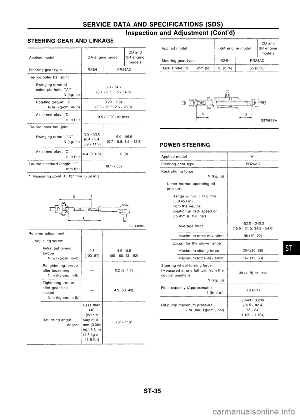
SERVICEDATAANDSPECIFICATIONS (50S)
Inspection andAdjustment (Cont'd)
STEERING GEARANDLINKAGE
CDand
Applied model GA
engine model SRengine
models
Steering geartype R24NPR24AC
Tie-rod outerballjoint
Swinging forceat
6.9-64.7
cotter pinhole: "A"
(0.7-6.6, 1.5-14.6)
N (kg, Ib)
Rotating torque:"B" 0.29
-294
N'm (kg-em, in-Ib) (30
-30.0, 26-260)
Axial endplay: "C"
0.5(0.020) orless
mm (in)
Tie-rod innerballjoint
.
Swinging force":"A" 3.9
-53.0
6.9-569
(0.4 -5.4,
N (kg, Ib)
0.9-11.9) (07
-58,1.5 -12.8)
Axial endplay: "C"
0.4(0.016)
a
(0)
mm (in)
Tie-rod standard length"L"
187(7.36)
mm (in)
". Measuring point
[f:
137 mm (5.39 in)]
SST488C
Retainer adjustment
Adjusting screw
Initial tightening
984.9
-5.9
torque (100,87)(50-60, 43-52)
Nm (kg-em, in-Ib)
Retightening torque
after loosening
-
02
(2,1.7)
N'm (kg-em, in-Ib)
Tightening torque
after gear has
-
49(50, 43)
settled
N'm (kg-em, in-Ib)
Lessthan
60'
[Within
Returning angle play
of0.1
70'-110'
degree mm
(0.004
in)/15 N'm
(1.5 kg-m,
11 ft-Ib)] CD
and
Applied model GAengine model SRengine
models
Steering geartype R24N
PR24AC
Rack stroke "S" mm(in) 70(2.76) 65(2.56)
POWER STEERING
Applied model All
Steering geartype PR24AC
Rack sliding force
N(kg, Ib)
Under normal operating oil
pressure
Range within ~.115 mm
(:1:0.453 in)
from theneutral
position atrack speed of
3.5 mm (0.138 in)/s
Average force 1520
-2403
(15.5 -24.5, 34.2-54.0)
Maximum forcedeviation 98(10, 22)
Except forthe above range
Maximum slidingforce 294(30, 66)
Maximum forcedeviation 147
(15, 33)
Steering wheelturning force
(Measured atone fullturn from the
39(4, 9)or less
neutral position)
N(kg, Ib)
Fluid capacity (Approximate)
0.9(3/4)
f
(Imp qt)
7,649-8,238
Oil pump maximum pressure (76.5
-82.4,
kPa (bar, kg/em?, psi) 78-84,
1,109 -1,194)
•
ST-35
Page:
< prev 1-8 9-16 17-24