Page 1500 of 1701
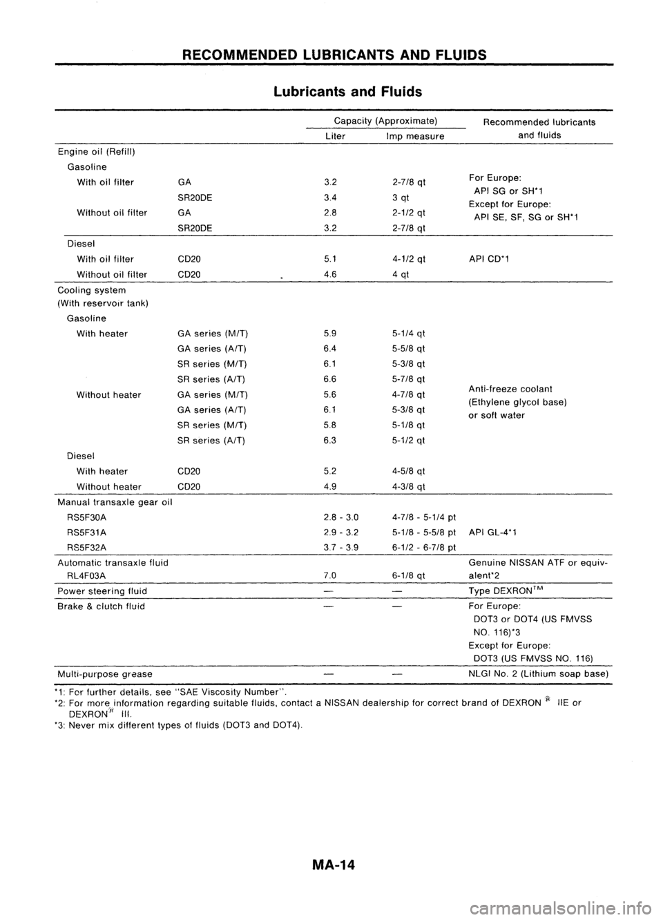
RECOMMENDEDLUBRICANTSANDFLUIDS
Lubricants andFluids
Capacity (Approximate)
Liter Impmeasure Recommended
lubricants
and fluids
Anti-freeze coolant
(Ethylene glycolbase)
or soft water
5-1/4
qt
5-5/8
qt
5-3/8
qt
5-7/8
qt
4-7/8
qt
5-3/8
qt
5-1/8
qt
5-1/2
qt
3.2
2-7/8
qt For
Europe:
3.4 3qt API
SGorSH*1
Except forEurope:
2.8
2-1/2
qt
APISE,SF,SGorSH*1
3.2
2-718
qt
5.1
4-1/2
qt API
CD*1
4.6 4qt
5.9
6.4
6.1
6.6
5.6
6.1
5.8
6.3
GA
SR20DE GA
SR20DE
GA series
(M/T)
GA series
(A/T)
SR series
(M/T)
SR series
(A/T)
GA series
(M/T)
GA series
(A/T)
SR series
(M/T)
SR series (AfT)
Without
heater
Without
oilfilter
Engine
oil(Refill)
Gasoline With oilfilter
Diesel With oilfilter CD20
Without oilfilter CD20
Cooling system
(With reservoir tank)
Gasoline With heater
Diesel With heater
Without heater CD20
CD20 5.2
4.9
4-5/8
qt
4-3/8
qt
Manual transaxle gearoil
RS5F30A
RS5F31A
RS5F32A
Automatic transaxlefluid
RL4F03A
Power steering fluid
Brake
&
clutch fluid
Multi-purpose grease
2.8
-3.0
2.9 -3.2
3,7 -3.9
7.0
4-7/8
-5-1/4
pt
5-1/8 -5-5/8
ptAPIGL-4*1
6-1/2 -6-7/8
pt
Genuine NISSANATForequiv-
6-1/8
qt alent*2
Type DEXRON™
For Europe:
0013
orDOT4 (USFMVSS
NO. 116)*3
Except forEurope:
DOT3 (USFMVSS NO.116)
NLGI NO.2 (Lithium soapbase)
*1: For further details, see"SAE Viscosity Number". _
*2: For morainformation regardingsuitablefluids,contact aNISSAN dealership forcorrect brandofDEXRON
'P:
liE or
DEXRON:
A
III.
*3: Never mixdifferent typesoffluids (DOT3 and
0014).
MA-14
Page 1536 of 1701
0
0
•
0
0
~ /0
H
H
0
0
(2)
4wheels
5 wheels
SMA785C
Radial
tires
CHASSIS
ANDBODY MAINTENANCE
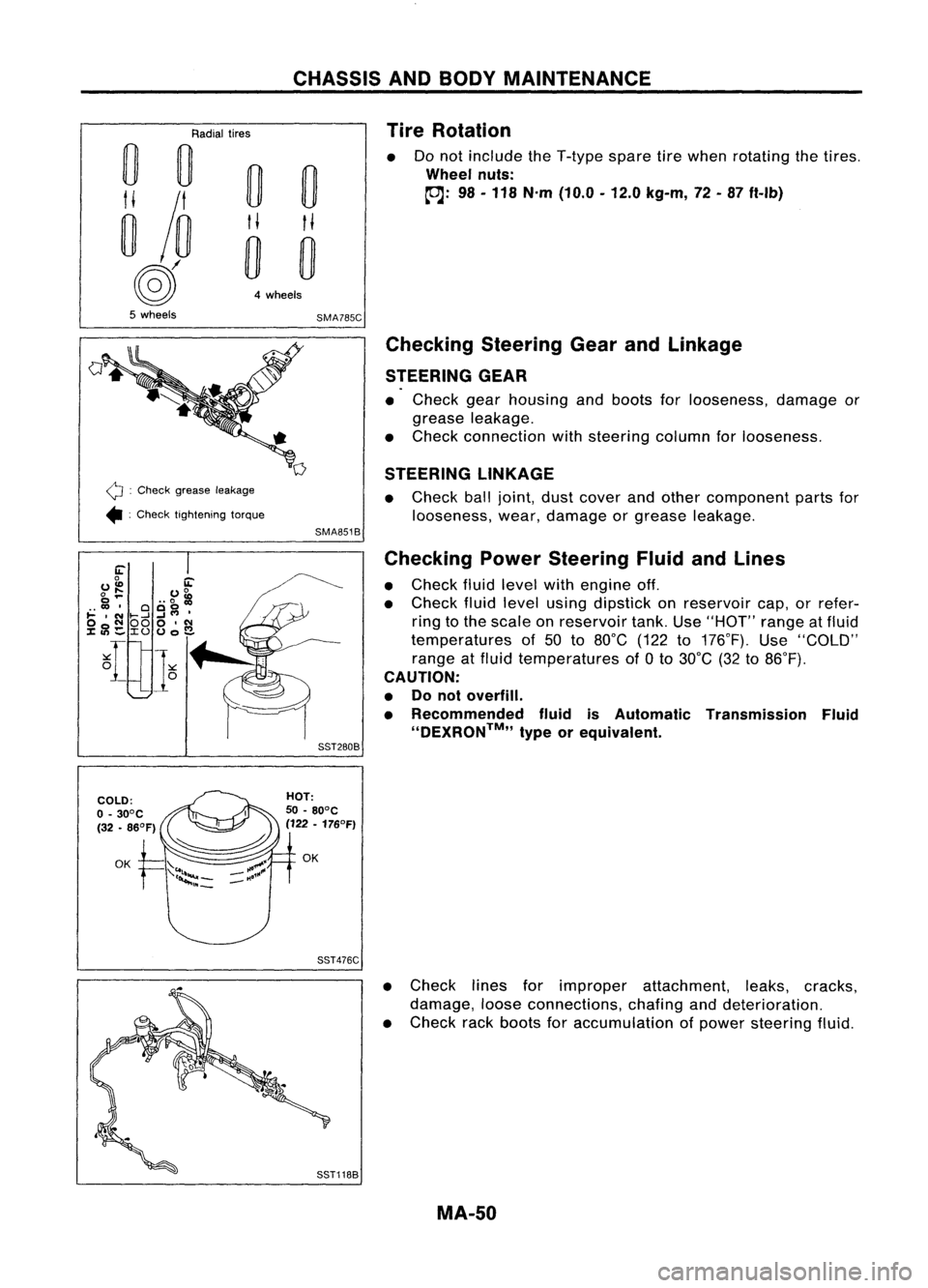
Tire Rotation
Do not include theT-type sparetirewhen rotating thetires .
Wheel nuts:
~: 98-118 N'm (10.0 -12.0 kg-m, 72-87 ft-Ib)
Q :
Check grease leakage
• :Check tightening torque
Checking
SteeringGearandLinkage
STEERING GEAR
• Check gearhousing andboots forlooseness, damageor
grease leakage.
• Check connection withsteering columnforlooseness.
STEERING LINKAGE
• Check balljoint, dustcover andother component partsfor
looseness, wear,damage orgrease leakage.
SMA851B
Checking PowerSteering FluidandLines
• Check fluidlevel withengine off.
• Check fluidlevel using dipstick onreservoir cap,orrefer-
ring tothe scale onreservoir tank.Use"HOT" rangeatfluid
temperatures of50 to80°C (122to176°F). Use"COLD"
range atfluid temperatures of
a
to 30°C (32to86°F).
CAUTION:
• Donot overfill.
• Recommended fluidisAutomatic Transmission Fluid
''DEXRON™,, typeorequivalent.
SST280B
SST476C
•Check linesforimproper attachment, leaks,cracks,
damage, looseconnections, chafinganddeterioration.
• Check rackboots foraccumulation ofpower steering fluid.
MA-50
Page 1667 of 1701
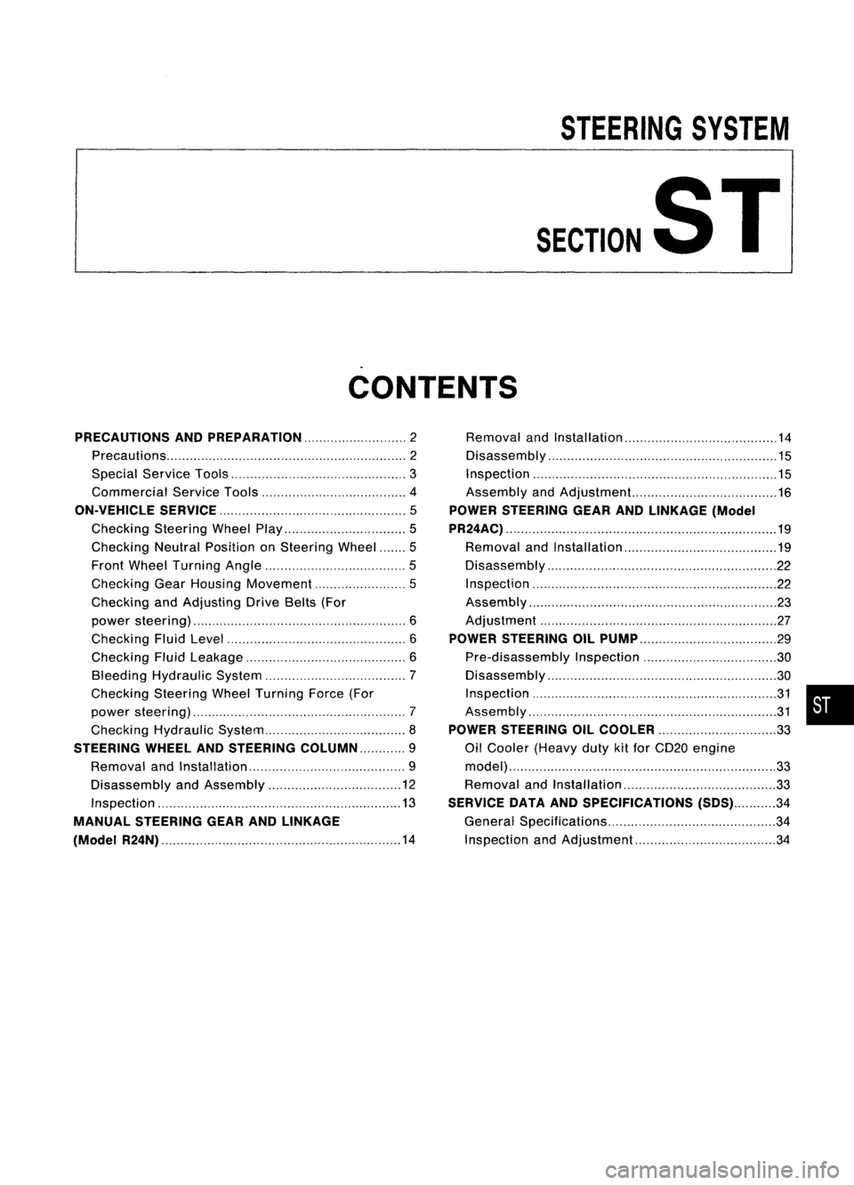
STEERINGSYSTEM
SECTIONST
CONTENTS
PRECAUTIONS ANDPREPARATION 2
Precautions 2
Special Service Tools 3
Commercial ServiceTools 4
ON-VEHICLE SERVICE
5
Checking SteeringWheelPlay 5
Checking NeutralPosition onSteering Wheel 5
Front Wheel Turning Angle 5
Checking GearHousing Movement 5
Checking andAdjusting DriveBelts(For
power steering) 6
Checking FluidLevel 6
Checking FluidLeakage 6
Bleeding Hydraulic System 7
Checking SteeringWheelTurning Force(For
power steering) 7
Checking Hydraulic System 8
STEERING WHEElANDSTEERING COLUMN 9
Removal andInstallation 9
Disassembly andAssembly 12
Inspection 13
MANUAL STEERING GEARANDLINKAGE
(Model R24N) 14
Removal
andInstallation 14
Disassembly 15
Inspection 15
Assembly andAdjustment... 16
POWER STEERING GEARANDLINKAGE (Model
PR24AC) 19
Removal andInstallation 19
Disassembly 22
Inspection 22
Assembly ,.. 23
Adjustment 27
POWER STEERING OILPUMP 29
Pre-disassembly Inspection 30
Disassembly 30
Inspection 31
Assembly 31
POWER STEERING OILCOOLER
33
Oil Cooler (Heavy dutykitfor CD20 engine
model) 33
Removal andInstallation 33
SERVICE DATAANDSPECIFICATIONS
(505)34
General Specifications 34
Inspection andAdjustment 34
•
Page 1672 of 1701
ON-VEHICLESERVICE
Checking andAdjusting DriveBelts(Forpower
steering)
Refer to"Checking DriveBelts" for"ENGINE MAINTENANCE"
in MA section.
SST476C
S
r
SST681B Checking
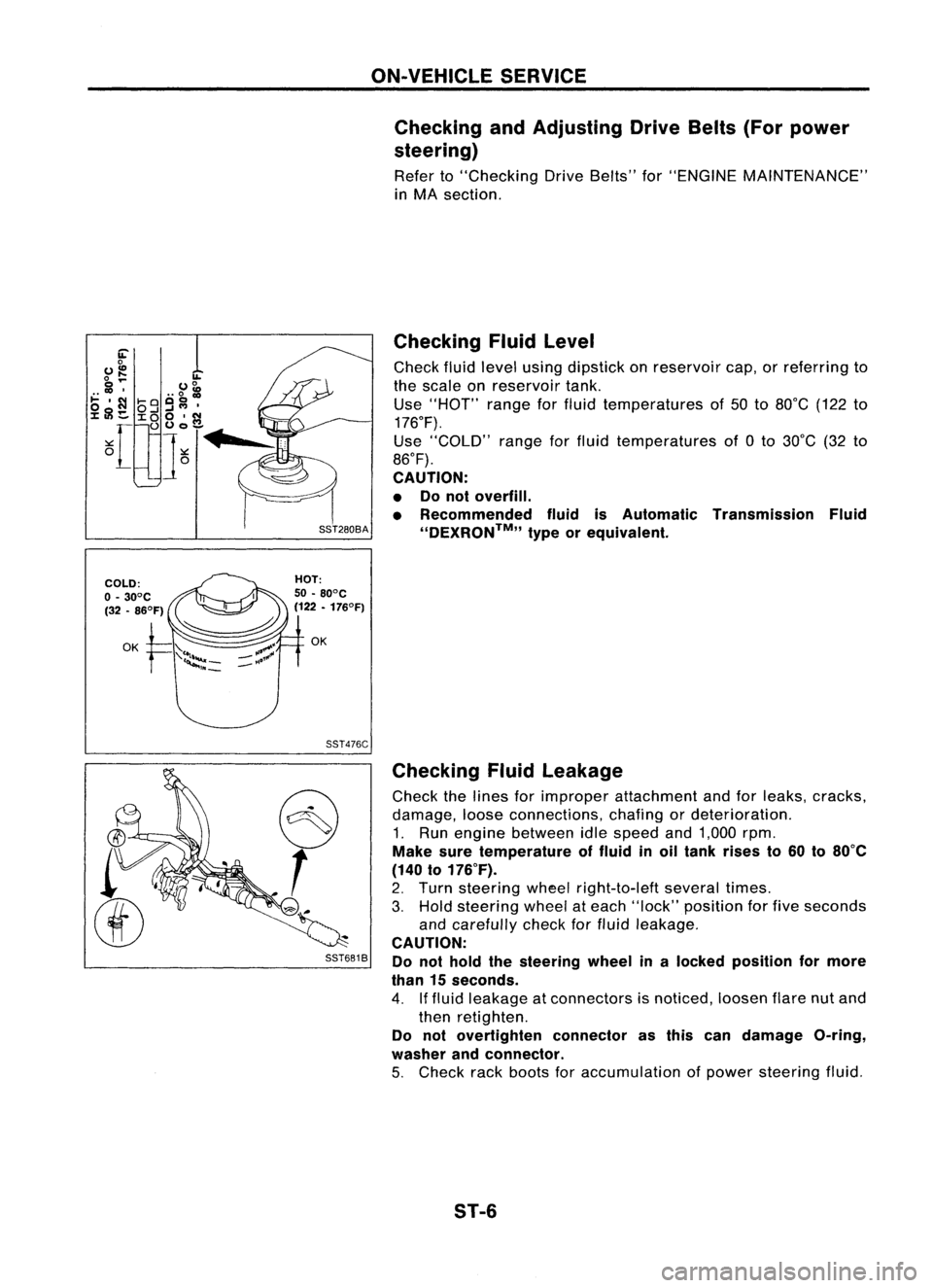
Fluidlevel
Check fluidlevel using dipstick onreservoir cap,orreferring to
the scale onreservoir tank.
Use "HOT" rangeforfluid temperatures of50 to80°C (122to
176°F).
Use "COLD" rangeforfluid temperatures of0to 30°C (32to
86°F).
CAUTION:
• Donot overfill.
• Recommended fluidisAutomatic Transmission Fluid
''DEXRON™,, typeorequivalent.
Checking Fluidleakage
Check thelines forimproper attachment andforleaks, cracks,
damage, looseconnections, chafingordeterioration.
1. Run engine between idlespeed and1,000 rpm.
Make suretemperature offluid inoil tank rises to60 to80°C
(140 to176°F).
2. Turn steering wheelright-to-Ieft severaltimes.
3. Hold steering wheelateach "lock" position forfive seconds
and carefully checkforfluid leakage.
CAUTION:
Do not hold thesteering wheelinalocked position formore
than 15seconds.
4. Iffluid leakage atconnectors isnoticed, loosenflarenutand
then retighten.
Do not overtighten connectorasthis candamage O-ring,
washer andconnector.
5. Check rackboots foraccumulation ofpower steering fluid.
ST-6
Page 1673 of 1701
SST491B
SST090B ON-VEHICLE
SERVICE
Bleeding Hydraulic System
1. Raise frontendofvehicle untilwheels areclear ofthe
ground.
2. Add fluid intooiltank tospecified level.Thenquickly turn
steering wheelfullytoright andleftand lightly touchsteer-
ing stoppers.
Repeat steering wheeloperation untilfluid level nolonger
decreases.
3. Start engine.
Repeat step2.above.
• Incomplete airbleeding willcause thefollowing tooccur.
When thishappens, bleedairagain.
a. Air bubbles inreservoir tank
b. Clicking noiseinoil pump
c. Excessive buzzinginoil pump
Fluid noise mayoccur inthe valve oroil pump. Thisiscommon
when thevehicle isstationary orwhile turning thesteering
wheel slowly. Thisdoes notaffect theperformance ordurabil-
ity ofthe system.
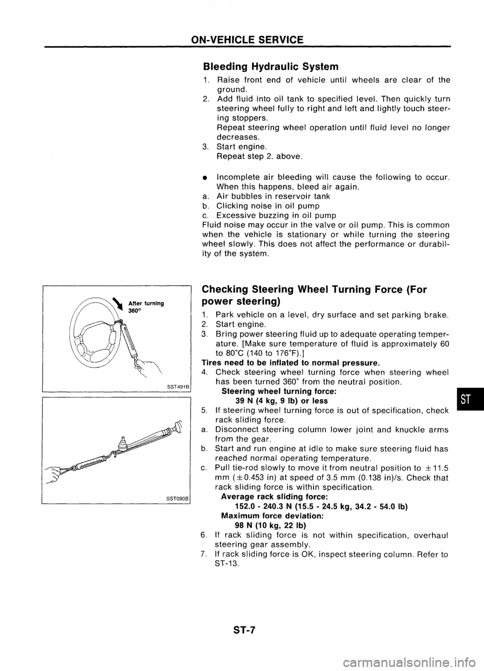
Checking SteeringWheelTurning Force(For
power steering)
1. Park vehicle onalevel, drysurface andsetparking brake.
2. Start engine.
3. Bring power steering fluiduptoadequate operating temper-
ature. [Make suretemperature offluid isapproximately 60
to 80°C (140to176°F).]
Tires needtobe inflated tonormal pressure.
4. Check steering wheelturning forcewhen steering wheel
has been turned 360°from theneutral position.
Steering wheelturning force: •
39 N(4 kg, 9Ib) orless
5.
If
steering wheelturning forceisout ofspecification, check
rack sliding force.
a. Disconnect steeringcolumnlowerjointandknuckle arms
from thegear.
b. Start andrunengine atidle tomake suresteering fluidhas
reached normaloperating temperature.
c. Pull tie-rod slowlytomove itfrom neutral position to
::l::
11.5
mm
(::l::
0.453 in)atspeed of3.5 mm (0.138 in)/s.Check that
rack sliding forceiswithin specification.
Average racksliding force:
152.0 -240.3 N(15.5 -24.5 kg,34.2 -54.0 Ib)
Maximum forcedeviation:
98 N(10 kg, 22Ib)
6.
If
rack sliding forceisnot within specification, overhaul
steering gearassembly.
7. Ifrack sliding forceisOK, inspect steering column.Referto
ST-13.
ST-7
Page 1687 of 1701
![NISSAN ALMERA N15 1995 Service Manual POWERSTEERING GEARANDLINKAGE (ModelPR24AC)
•
~ :N.m (kg-m. ft-lb)
f] :
Lubrication points
(With automatic
transmission fluid
"DEXRON'u" type
or equivalent)
I
@~~~~
~~(SRandCD
~ ~~ e NISSAN ALMERA N15 1995 Service Manual POWERSTEERING GEARANDLINKAGE (ModelPR24AC)
•
~ :N.m (kg-m. ft-lb)
f] :
Lubrication points
(With automatic
transmission fluid
"DEXRON'u" type
or equivalent)
I
@~~~~
~~(SRandCD
~ ~~ e](/manual-img/5/57349/w960_57349-1686.png)
POWERSTEERING GEARANDLINKAGE (ModelPR24AC)
•
~ :N.m (kg-m. ft-lb)
f] :
Lubrication points
(With automatic
transmission fluid
"DEXRON'u" type
or equivalent)
I
@~~~~
~~(SRandCD
~ ~~ enginemodels)
8
~78. 98
(8.0 •10.0,
58•72)
GA engine model
~ 37•46 (3.8 •4.7, 27.34)
CD and SRengine models
M
78.98
(8.0 •
10.0, 58•72)
(SR
,,'CD,",,",
m_"'7
~\Il~
m~
@,
~16.21
~~'" ~•'.1, ". 1S(
r
""'---l
, @
l"J
::'0' ,':0,
1
I
~ /7'
~y
@ "-~~(]
tGi ~
~m
@
t:;;J
~20.
26
(2.0 •2.7, 14•20)
SEC.
492
@)(]~\-
.~
~'
r
L
~to:J59' 74
20~
(6.0 •
7.5, 43.54)
_~ @Donotdisas~smble.
0
to:J 29•39
{3.0 .4.0,22. "~~
SST506CA
Pinion oilseal
Lock nut
Adjusting screw
Spring
Spring disc
G)
Rear cover cap
@
Rear housing assembly
@
Pinion sealring
@
Pinion assembly
CID
O-ring
@
Shim
(J)
@
@
@)
@ @
Washer
@
Spring seat
@
Retainer
@
Gear housing
@
Center bushing
@
Rack oilseal
@
Rack assembly
@
Rack sealring
@)
O-ring
@
Rack oilseal
@
Endcover assembly
@
Boot clamp
@
Dust boot
@
Boot band
@l
Steering gearspacer
@
Lock plate
@
Tie-rod innersocket
@
Tie-rod outersocket
@
Cotter pin
@
Gear housing tube
ST-21
Page 1688 of 1701
POWERSTEERING GEARANDLINKAGE (ModelPR24AC)
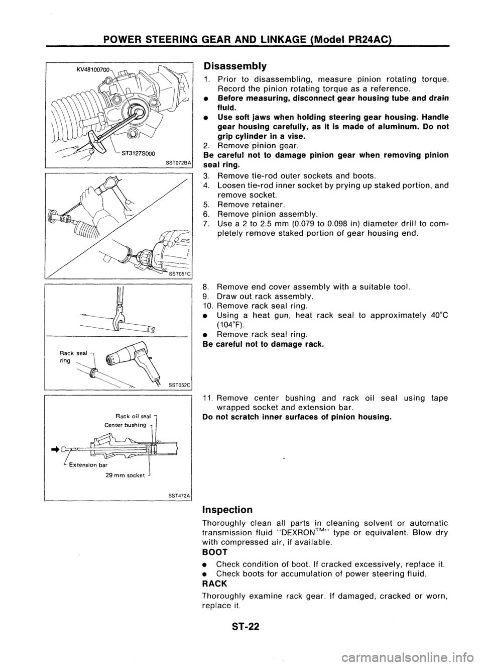
Disassembly
1. Prior todisassembling, measurepinionrotating torque.
Record thepinion rotating torqueasareference.
• Before measuring, disconnectgearhousing tubeanddrain
fluid.
• Use softjaws when holding steering gearhousing. Handle
gear housing carefully, asitis made ofaluminum. Donot
grip cylinder inavise.
2. Remove piniongear.
Be careful nottodamage piniongearwhen removing pinion
seal ring.
3. Remove tie-rodoutersockets andboots.
4. Loosen tie-rodinnersocket byprying upstaked portion, and
remove socket.
5. Remove retainer.
6. Remove pinionassembly.
7. Use a2to 2.5 mm (0.079 to0.098 in)diameter drilltocom-
pletely remove stakedportion ofgear housing end.
8. Remove endcover assembly withasuitable tool.
9. Draw outrack assembly.
10. Remove rackseal ring.
• Using aheat gun,heat racksealtoapproximately 40°C
(104°F).
• Remove racksealring.
Be careful nottodamage rack.
11. Remove centerbushing andrack oilseal using tape
wrapped socketandextension bar.
Do not scratch innersurfaces ofpinion housing .
.. !tension bar
29 mm socket
SST472AInspection
Thoroughly cleanallparts incleaning solventorautomatic
transmission fluid''DEXRON™,, typeorequivalent. Blowdry
with compressed air,ifavailable.
BOOT
• Check condition ofboot. Ifcracked excessively, replaceit.
• Check bootsforaccumulation ofpower steering fluid.
RACK
Thoroughly examinerackgear. Ifdamaged, crackedorworn,
replace it.
ST-22
Page 1693 of 1701
POWERSTEERING GEARANDLINKAGE (ModelPR24AC)
Assembly (Cont'd)
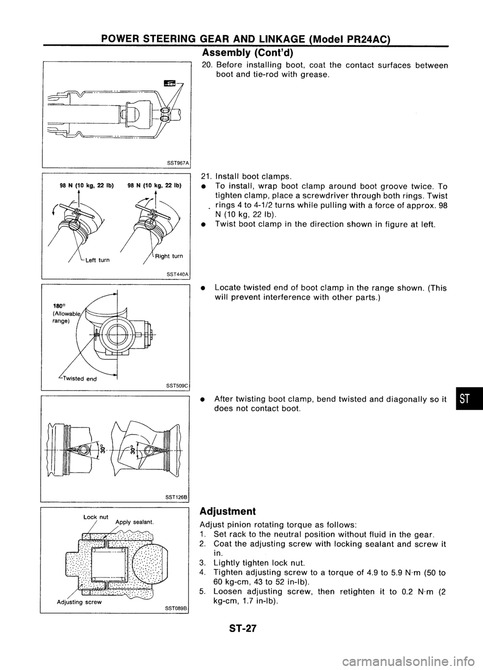
20. Before installing boot,coatthecontact surfaces between
boot andtie-rod withgrease.
88T967A
21.Install bootclamps.
• Toinstall, wrapbootclamp around bootgroove twice.To
tighten clamp,placeascrewdriver throughbothrings. Twist
rings 4to 4-1/2 turns while pulling withaforce ofapprox. 98
N (10 kg,22Ib).
• Twist bootclamp inthe direction showninfigure atleft.
88T440A
•Locate twisted endofboot clamp inthe range shown. (This
will prevent interference withother parts.)
88TS09C
88T1268
•
After twisting bootclamp, bendtwisted anddiagonally soit •
does notcontact boot.
Adjusting screw
88T0898Adjustment
Adjust pinionrotating torqueasfollows:
1. Set rack tothe neutral position withoutfluidinthe gear.
2. Coat theadjusting screwwithlocking sealant andscrew it
in.
3. Lightly tighten locknut.
4. Tighten adjusting screwtoatorque of4.9 to5.9 N'm (50to
60 kg-em, 43to52 in-Ib).
5. Loosen adjusting screw,thenretighten itto 0.2 N'm (2
kg-em, 1.7in-Ib).
ST-27