1995 NISSAN ALMERA N15 check engine light
[x] Cancel search: check engine lightPage 963 of 1701
@
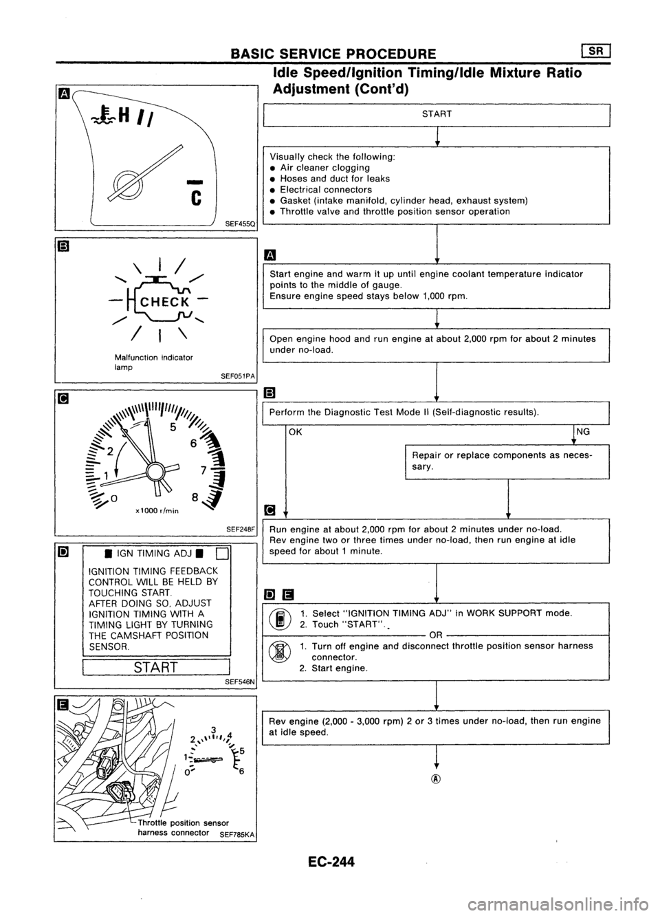
START
Visually checkthefollowing:
• Air cleaner clogging
• Hoses andduct forleaks
• Electrical connectors
• Gasket (intakemanifold, cylinderhead,exhaust system)
• Throttle valveandthrottle position sensoroperation
m
Start engine andwarm itup until engine coolant temperature indicator
points tothe middle ofgauge.
Ensure enginespeedstaysbelow 1,000rpm.
1
Open engine hoodandrunengine atabout 2,000rpmforabout 2minutes
under no-load.
Ii]
Perform theDiagnostic TestMode
1\
(Self-diagnostic results).
OK ~NG
Repair orreplace components asneces-
sary.
[!J
Run engine atabout 2,000rpmforabout 2minutes underno-load.
Rev engine twoorthree times under no-load, thenrunengine atidle
speed forabout 1minute .
li]1!I
00
1.
Select "IGNITION TIMINGADJ"inWORK SUPPORT mode.
2. Touch "START" .
.
OR
00
1.
Turn offengine anddisconnect throttleposition sensorharness
connector.
2. Start engine.
Rev engine (2,000-3,000 rpm)2or 3times under no-load, thenrunengine
at idle speed.
t
Throttle position sensor
harness connector SEF785KASEF051PA
BASIC
SERVICE PROCEDURE Em
Idle Speedllgnition TiminglldleMixtureRatio
Adjustment (Cont'd)
SEF248F
SEF455Q
Malfunction indicator
lamp \
I/
'~,,/
- CHECK-
,,/
........
/ I\
Ii] •IGN TIMING ADJ.
D
IGNITION TIMINGFEEDBACK
CONTROL WILLBEHELD BY
TOUCHING START.
AFTER DOING SO,ADJUST
IGNITION TIMINGWITHA
TIMING LIGHTBYTURNING
THE CAMSHAFT POSITION
SENSOR.
I
START
I
SEF546N
EC-244
Page 964 of 1701
AEC804
•
Ii
L
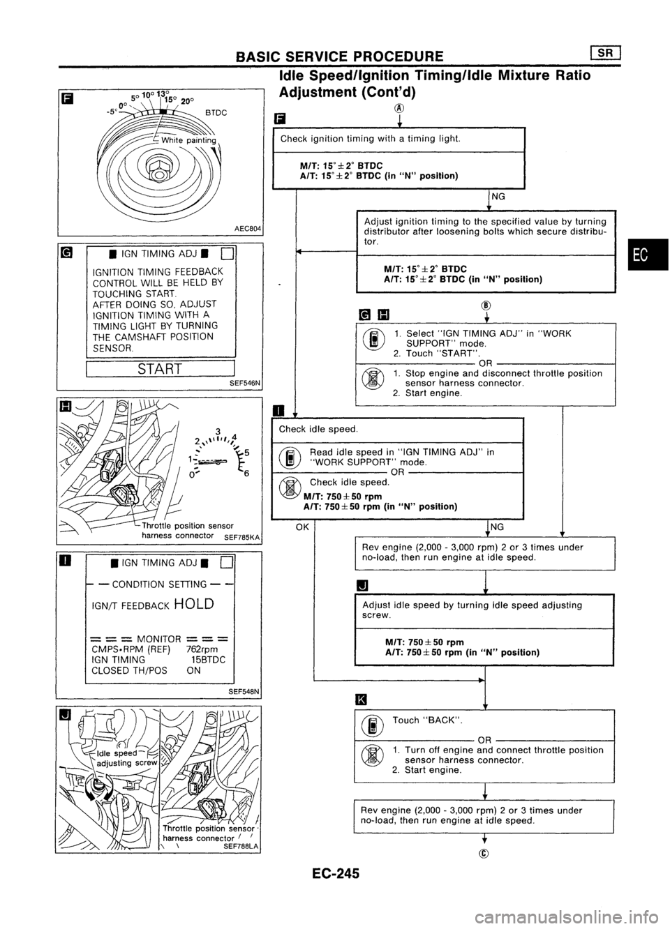
Check ignition timingwithatiming light.
M/T:
15°::l:2°BTDC
A/T: 15°::l: 2°BTDC (inUN" position)
NG
Adjust ignition timingtothe specified valuebyturning
distributor afterloosening boltswhich secure distribu-
tor.
M/T:
15°::l:2°BTDC
.
A/T:
15°::l: 2°BTDC (inUN" position)
~IIJ
@
~
00
1.
Select
"IGNTIMING ADJ"in"WORK
SUPPORT" mode.
2. Touch "START".
OR
@
1.
Stop engine anddisconnect throttleposition
sensor harness connector.
2. Start engine.
0
Check idlespeed.
@ Read
idlespeed in"IGN TIMING ADJ"in
"WORK SUPPORT" mode.
OR
@
Checkidlespeed.
M/T:
750::l: 50rprn
A/T: 750::l: 50rprn (inUN" position)
OK NG
Rev engine (2,000-3,000 rpm)2or 3times under
no-load, thenrunengine atidle speed.
1.1
Adjust idlespeed byturning idlespeed adjusting
screw.
M/T:
750::l: 50rpm
A/T: 750::l: 50rprn (inUN" position)
II
00
Touch
"BACK".
OR
@
1.
Turn offengine andconnect throttleposition
sensor harness connector.
2. Start engine.
L
Rev engine (2,000-3,000 rpm)2or 3times under
no-load, thenrunengine atidle speed.
-.
BASIC
SERVICE PROCEDURE
[]K]
Idle Speed/Ignition Timing/IdleMixtureRatio
Adjustment (Cont'd)
@
SEF548N
/ / I
Throttle position sensor-
harness connector /
I
\ \ SEF788LASEF546N
START
•
IGN TIMING ADJ.
0
IGNITION TIMINGFEEDBACK
CONTROL WILLBEHELD BY
TOUCHING START
AFTER DOING SO,ADJUST
IGNITION TIMINGWITHA
TIMING LIGHTBYTURNING
THE CAMSHAFT POSITION
SENSOR
= ==
MONITOR
==
=
CMPS.RPM (REF)762rpm
IGN TIMING 15BTDC
CLOSED TH/POS ON
Ii
o •
IGN TIMING ADJ.
0
I- -
CONDITION SETIING--
IGN/T FEEDBACK HOLD
EC-245
Page 969 of 1701
ON-BOARDDIAGNOSTIC SYSTEMDESCRIPTION
\ I/
'~/'
- CHECK-
/
.......
/ I\
SEF051P
Malfunction
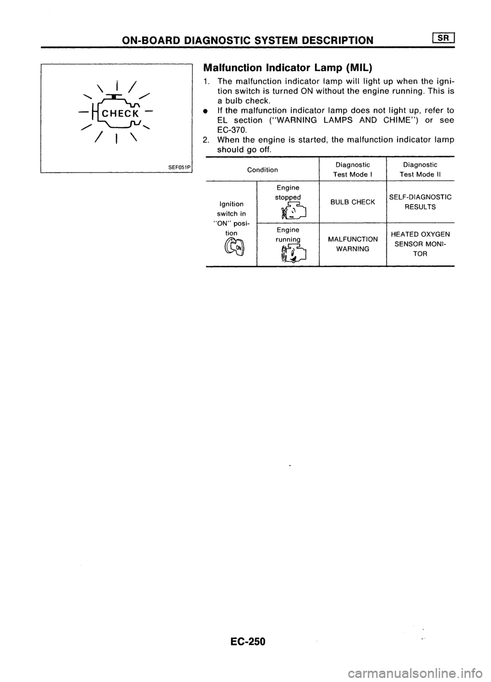
Indicatorlamp(Mil)
1. The malfunction indicatorlampwilllight upwhen theigni-
tion switch isturned ONwithout theengine running. Thisis
a bulb check.
• Ifthe malfunction indicatorlampdoes notlight up,refer to
EL section ("WARNING LAMPSANDCHIME") orsee
EC-370.
2. When theengine isstarted, themalfunction indicatorlamp
should gooff.
Condition Diagnostic
Diagnostic
Test Mode I TestMode II
Engine
stopped BULBCHECK SELF-DIAGNOSTIC
Ignition
0
RESULTS
switch in
"ON" posi-
tion Engine
HEATEDOXYGEN
~ running
MALFUNCTION
SENSORMONI-
ID
WARNING
TOR
EC-250
Page 975 of 1701
ON-BOARDDIAGNOSTIC SYSTEMDESCRIPTION
CONSULT (Cont'd)
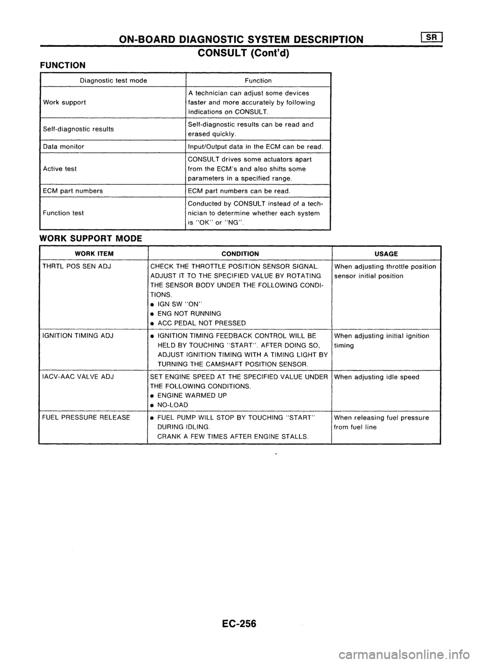
FUNCTION
Diagnostictestmode Function
A technician canadjust somedevices
Work support
fasterandmore accurately byfollowing
indications onCONSULT.
Self-diagnostic results Self-diagnostic
resultscanberead and
erased quickly.
Data monitor
Input/Outputdatainthe ECM canberead.
CONSULT drivessomeactuators apart
Active test fromtheECM's andalso shifts some
parameters inaspecified range.
ECM partnumbers
ECMpartnumbers canberead.
Conducted byCONSULT insteadofatech-
Function test
niciantodetermine whethereachsystem
is "OK" or"NG".
WORK SUPPORT MODE
WORK ITEM
CONDITION USAGE
THRTL POSSENADJ
CHECKTHETHROTTLE POSITIONSENSORSIGNAL. Whenadjusting throttleposition
ADJUST ITTO THE SPECIFIED VALUEBYROTATING
sensorinitialposition
THE SENSOR BODYUNDER THEFOLLOWING CONDI-
TIONS .
• IGN SW"ON"
• ENG NOTRUNNING
• ACC PEDAL NOTPRESSED
IGNITION TIMINGADJ
•IGNITION TIMINGFEEDBACK CONTROLWILLBE
Whenadjusting initialignition
HELD BYTOUCHING "START".AFTERDOINGSO, timing
ADJUST IGNITION TIMINGWITHATIMING LIGHTBY
TURNING THECAMSHAFT POSITIONSENSOR.
IACV-AAC VALVEADJ
SETENGINE SPEEDATTHE SPECIFIED VALUEUNDER
Whenadjusting idlespeed
THE FOLLOWING CONDITIONS.
• ENGINE WARMED UP
• NO-LOAD
FUEL PRESSURE RELEASE •FUEL PUMP WILLSTOP BYTOUCHING "START"
Whenreleasing fuelpressure
DURING IDLING.
fromfuelline
CRANK AFEW TIMES AFTER ENGINE STALLS
EC-256
Page 978 of 1701

ON-BOARDDIAGNOSTIC SYSTEMDESCRIPTION
CONSULT (Conl'd)
ACTIVE TESTMODE
TEST ITEM CONDITION JUDGEMENTCHECKITEM(REMEDY)
• Engine: Returntothe original
•Harness andconnector
FUEL INJECTION trouble
condition
Iftrouble symptom disappears,
•Fuel injectors
• Change theamount offuel
seeCHECK ITEM.
•Heated oxygen sensor
injection usingCONSULT .
• Engine: Afterwarming up,idle
IACV-AACIV the
engine.
Enginespeedchanges according •Harness andconnector
OPENING •
Change theIACV-AAC valve
tothe opening percent. •
IACV-AAC valve
opening percentusingCON-
SULT.
• Engine: Returntothe original
•Harness andconnector
ENG COOLANT trouble
condition
Iftrouble symptom disappears, •
Engine coolant temperature
• Change theengine coolant
.
TEMP see
CHECK ITEM. sensor
temperature indicationusing
•Fuel injectors
CONSULT .
• Engine: Returntothe original
trouble condition
Iftrouble symptom disappears,
IGNITION TIMING•Timing light:Set •
Adjust initialignition timing
• Retard theignition timingusingsee
CHECK ITEM.
CONSULT.
• Engine: Afterwarming up,idle •
Harness andconnector
the engine. •
Compression
POWER
•
AIC
switch "OFF"
Enginerunsrough ordies. •
Injectors
BALANCE •
Shift lever "N" •
Power transistor
• Cut offeach injector signalone •
Spark plugs
at atime using CONSULT . •
Ignition coils
• Ignition switch:ON
•Harness andconnector
COOLING FAN•
Turn thecooling fan"ON" andCooling
fanmoves andstops.
•Cooling fanmotor
"OFF" usingCONSULT .
• Ignition switch:ON(Engine
FUEL PUMP stopped)
Fuelpump relaymakes theoper- •
Harness andconnector
RELAY •
Turn thefuel pump relay"ON"
atingsound. •
Fuel pump relay
and "OFF" usingCONSULT
and listen tooperating sound.
EGRC •
Ignition switch:ON
• Turn solenoid valve"ON"and Solenoid
valvemakes anoperat- •
Harness andconnector
SOLENOID "OFF"withtheCONSULT andingsound. •
Solenoid valve
VALVE listentooperating sound.
SELF-LEARNING •
In this test, thecoefficient ofself-learning controlmixture ratioreturns tothe original coefficient by
CONT touching
"CLEAR" onthe screen.
EC-259
•
Page 980 of 1701
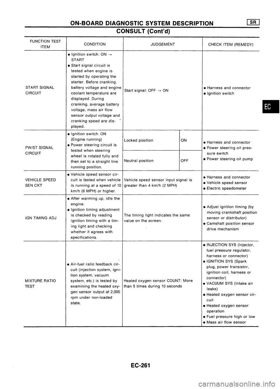
ON-BOARDDIAGNOSTIC SYSTEMDESCRIPTION
CONSULT (Cont'd)
FUNCTION TEST
CONDITION
ITEM JUDGEMENT
CHECKITEM(REMEDY)
• Ignition switch:ON
->
START
• Start signal circuit is
tested whenengine is
started byoperating the
starter. Beforecranking,
START SIGNAL batteryvoltage andengine
Startsignal: OFF
->
ON •
Harness andconnector
CIRCUIT coolanttemperature are
•Ignition switch
displayed. During
cranking, averagebattery
voltage, massairflow
sensor outputvoltage and
cranking speedaredis-
.
played .
• Ignition switch:ON
(Engine running)
Lockedposition ON
•Harness andconnector
PW/ST SIGNAL •
Power steering circuitis
•Power steering oilpres-
CIRCUIT tested
whensteering
sureswitch
wheel isrotated fullyand
•Power steering oilpump
then settoastraight lineNeutral
position OFF
running position.
• Vehicle speedsensor cir-
•Harness andconnector
VEHICLE SPEED cuitistested whenvehicle Vehiclespeedsensor inputsignal is
•Vehicle speedsensor
SEN CKT isrunning ataspeed of10 greater than4km/h (2MPH)
•Electric speedometer
km/h (6MPH) orhigher .
• After warming up,idle the
engine. •Adjust ignition timing(by
• Ignition timingadjustment
movingcrankshaft position
is checked byreading Thetiming lightindicates thesame
IGN TIMING ADJ
ignitiontimingwithatim- valueonthe screen. sensor
ordistributor)
ing light andchecking •
Camshaft positionsensor
whether itagrees with drive
mechanism
specifications. •INJECTION SYS(Injector,
fuel pressure regulator,
harness orconnector)
• Air-fuel ratiofeedback cir- •
IGNITION SYS(Spark
cuit (injection system,igni- plug,
power transistor,
ignition coil,harness or
tion system, vacuum
connector)
MIXTURE RATIO system,
etc.)istested byHeated oxygen sensorCOUNT: More
•VACUUM SYS(Intake air
TEST examining
theheated oxy-than
5times during 10seconds
leaks)
gen sensor outputat2,000
•Heated oxygen sensorcir-
rpm under non-loaded
cuit
state. •Heated oxygen sensor
operation
• Fuel pressure highorlow
• Mass airflow sensor
EC-261
•
Page 990 of 1701
TROUBLEDIAGNOSIS -General Descrip_ti_on
1S_R_'
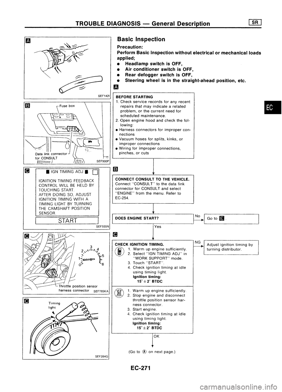
Basic Inspection
Precaution:
Perform BasicInspection withoutelectrical ormechanical loads
applied;
• Headlamp switchisOFF,
• Air conditioner switchisOFF,
• Rear defogger switchisOFF,
• Steering wheelisinthe straight-ahead position,etc.
m
BEFORE STARTING
1. Check service records forany recent •
repairs thatmay indicate arelated
problem, orthe current needfor
scheduled maintenance.
2. Open engine hoodandcheck thefol-
lowing:
• Harness connectors forimproper con-
nections
• Vacuum hosesforsplits, kinks,or
improper connections
• Wiring forimproper connections,
pinches, orcuts
Goto
(I.
No
CONNECT
CONSULTTOTHE VEHICLE.
Connect "CONSULT" tothe data link
connector forCONSULT andselect
"ENGINE" fromthemenu. Referto
EC-254.
DOES ENGINE START?
\\
~
~ SEF1421
START
•
IGN TIMING ADJ.
0
IGNITION TIMINGFEEDBACK
CONTROL WILLBEHELD BY
TOUCHING START
AFTER DOING SO,ADJUST
IGNITION TIMINGWITHA
TIMING LIGHTBYTURNING
THE CAMSHAFT POSITION
SENSOR.
SEF555N
Yes
CHECK IGNITION TIMING.
(ij\
1.Warm upengine sufficiently.
~ 2.Select "IGNTIMING ADJ"in
"WORK SUPPORT" mode.
3. Touch "START".
4. Check ignition timingatidle
using timing light.
Ignition timing:
15°::f:2° BTDC
~ 1Warm upengine sufficiently.
~ 2:
Stop engine anddisconnect
throttle position sensorhar-
ness connector.
3. Start engine.
4. Check ignition timingatidle
using timing light.
Ignition timing:
15°::f:2° BTDC
OK
(Go to
@
onnext page.) Adjust
ignition timingby
turning distributor.
EC-271
Page 991 of 1701
![NISSAN ALMERA N15 1995 Service Manual
I!]
CHECK IDLEADJ. SCREW INITIALSET
NG
Adjust engine speedby
---..
RPM.
turningidleadjusting
00
1.
Select "IGNTIMING ADJ"in screw.
"WORK SUPPORT" mode.
2. When touching "STAR NISSAN ALMERA N15 1995 Service Manual
I!]
CHECK IDLEADJ. SCREW INITIALSET
NG
Adjust engine speedby
---..
RPM.
turningidleadjusting
00
1.
Select "IGNTIMING ADJ"in screw.
"WORK SUPPORT" mode.
2. When touching "STAR](/manual-img/5/57349/w960_57349-990.png)
I!]
CHECK IDLEADJ. SCREW INITIALSET
NG
Adjust engine speedby
---..
RPM.
turningidleadjusting
00
1.
Select "IGNTIMING ADJ"in screw.
"WORK SUPPORT" mode.
2. When touching "START",
does engine speedfallto
750:!: 50rpm
(AfT
in
"N"
posi-
tion)?
OR
00
Does
engine runat750:!: 50rpm
(AfT
In
"N"
position)?
OK
Reconnect throttleposition sensorhar-
ness connector.
Ii
CHECK THROTTLE POSITIONSENSOR
NG
Adjust outputvoltage to
IDLE POSITION.
---..
0.50Vbyrotating throttle
00
1.
Perform ''THRTLPOSSEN
positionsensorbody.
ADJ" in"WORK SUPPORT"
1
mode.
2. Check thatoutput voltage of
RESETIDLEPOSITION
throttle position sensoris
MEMORY.
approx. 0.35to0.65V (Throttle
1.Warm upengine suffi-
valve fullycloses.) and"CLSD ciently.
2. Turn ignition switch
THLIPOSI" stays"ON".
"OFF"andwait at
OR least5seconds.
00
Measure
outputvoltage ofthrot- 3.
Disconnect throttle
position sensorhar-
tie position sensorusing
nessconnector.
voltmeter, andcheck thatitis
4.
Start engine andwait
approx. 0.35toO.65V. (Throttle at
least 5seconds in
"N" position.
valve fullyclosed.)
5.Reconnect throttle
OK • position
sensorhar-
ness connector while
running engine.
~
1
,
THRTL
POSSEN O,52V
SEF165P
•••
ADJMONITOR •••
TROUBLE
DIAGNOSIS -General Description
Basic Inspection (Cont'd)
@
========
MONITOR
========
CMPS.RPM (REF)Orpm
CLSDTHUP ON
Ii
•
THRTL POSSENADJ
.0
I!]
•IGN TIMING ADJ.
0
IGNITION TIMINGFEEDBACK
CONTROL WILLBEHELD BY
TOUCHING START
AFTER DOING SO,ADJUST
IGNITION TIMINGWITHA
TIMING LIGHTBYTURNING
THE CAMSHAFT POSITION
SENSOR
I
START
I
SEF546N
CID
(Go tonext page)
EC-272