1995 NISSAN ALMERA N15 check engine light
[x] Cancel search: check engine lightPage 996 of 1701
TROUBLEDIAGNOSIS -General Description
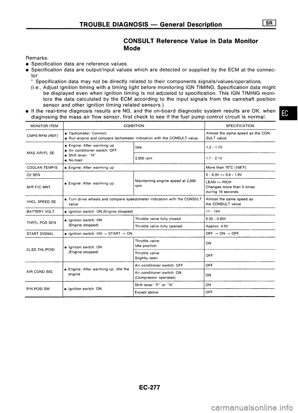
CONSULT Reference ValueinData Monitor
Mode
Remarks:
• Specification dataarereference values.
• Specification dataareoutput/input valueswhicharedetected orsupplied bythe ECM atthe connec-
tor.
*
Specification datamaynotbedirectly relatedtotheir components signals/values/operations.
(Le., Adjust ignition timingwithatiming lightbefore monitoring IGNTIMING. Specification datamight
be displayed evenwhen ignition timingisnot adjusted tospecification. ThisIGNTIMING moni-
tors thedata calculated bythe ECM according tothe input signals fromthecamshaft position
sensor andother ignition timingrelated sensors.)
• Ifthe real-time diagnosis resultsareNG, andtheon-board diagnostic systemresultsareOK, when •
diagnosing themass airflow sensor, firstcheck tosee ifthe fuel pump control circuitisnormal.
MONITOR ITEM CONDITION
SPECIFICATION
CMPS.RPM (REF)•
Tachometer: Connect Almostthesame speed asthe CON-
• Run engine andcompare tachometer indicationwiththeCONSULT value.SULTvalue.
• Engine: Afterwarming up
Idle 1.3-1.7V
MAS AIR/FL SE •
Air conditioner switch:OFF
• Shift lever: "N"
• No-load 2,000
rpm 1.7-2.1V
COOLAN TEMPIS •
Engine: Afterwarming up More
than70°C (15S0F)
02 SEN 0-
0.3V .....0.6 -1.0V
• Engine: Afterwarming up Maintaining
enginespeedat2,000
LEAN
+-->
RICH
MIR
FIC
MNT rpm
Changesmorethan5times
during 10seconds.
VHCL SPEED SE•
Turn drive wheels andcompare speedometer indicationwiththeCONSULT Almostthesame speed as
value the
CONSULT value
BATTERY VOLT •
Ignition switch:ON(Engine stopped) 11
-14V
• Ignition switch:ON Throttle
valvefullyclosed
0.35-0.65V
THRTL
pas
SEN
(Enginestopped)
Throttlevalvefullyopened Approx.4.0V
START SIGNAL •
Ignition switch:ON
->
START
->
ON OFF
->
ON
->
OFF
Throttle valve:
ON
• Ignition switch:ON Idle
position
CLSD THLIPOSI
(Enginestopped)
Throttlevalve:
Slightly open OFF
Air conditioner switch:OFF OFF
AIR COND SIG •
Engine: Afterwarming up,idle the
engine Air
conditioner switch:ON
ON
(Compressor operates)
Shift lever "P"or"N" ON
PIN POSI SW •
Ignition switch:ON
Exceptabove OFF
EC-277
Page 1008 of 1701
TROUBLEDIAGNOSIS FOROTC11
Rotor plate
SEF6138
180
0
signal slitfor NO.1 cylinder
\\\\""I"~'11111
1
0
signal slit
\\\\\ d'"
/11;
:£
';\'0\
I//..;:
#'
/%
$ ~
180
0
signal slit
f
0
%
o
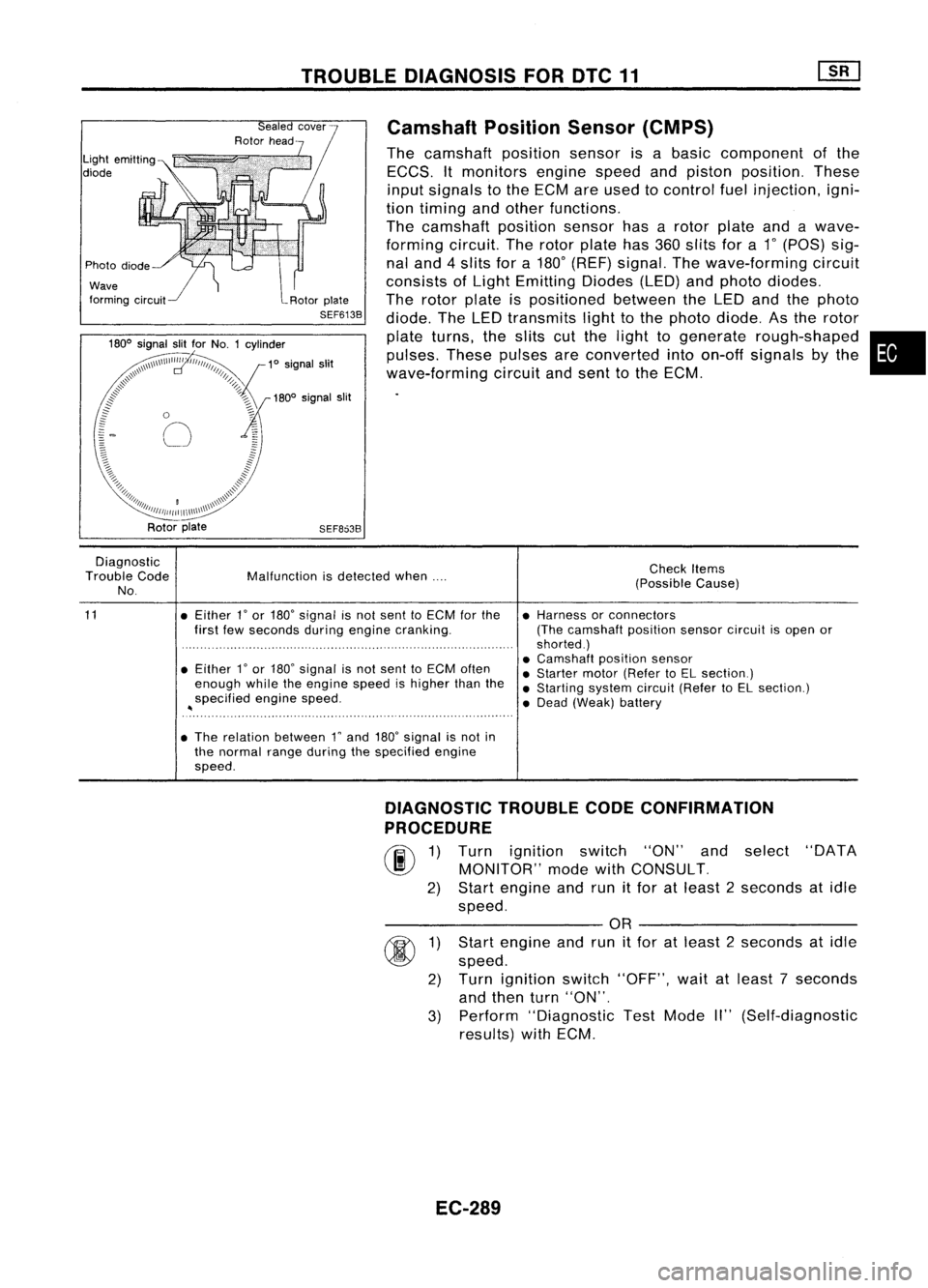
Camshaft
PositionSensor(CMPS)
The camshaft positionsensorisabasic component ofthe
ECCS. Itmonitors enginespeedandpiston position. These
input signals tothe ECM areused tocontrol fuelinjection, igni-
tion timing andother functions.
The camshaft positionsensorhasarotor plate andawave-
forming circuit.Therotor plate has360slits fora
1"
(POS) sig-
nal and 4slits fora180
0
(REF) signal. Thewave-forming circuit
consists ofLight Emitting Diodes(LED)andphoto diodes.
The rotor plate ispositioned betweentheLED andthephoto
diode. TheLED transmits lighttothe photo diode. Asthe rotor
plate turns, theslits cutthe light togenerate rough-shaped •
pulses. Thesepulses areconverted intoon-off signals bythe
wave-forming circuitandsent tothe ECM.
Rotor plate
SEF8638
Diagnostic
Trouble Code
No.
11
Malfunction
isdetected when....
• Either 1
0
or 180
0
signal isnot sent toECM forthe
first fewseconds duringengine cranking.
• Either
r
or 180" signal isnot sent toECM often
enough whiletheengine speedishigher thanthe
specified enginespeed.
~
• The relation between rand180
0
signal isnot in
the normal rangeduring thespecified engine
speed. Check
Items
(Possible Cause)
• Harness orconnectors
(The camshaft positionsensorcircuitisopen or
shorted.)
• Camshaft positionsensor
• Starter motor(Refer toEL section.)
• Starting systemcircuit(RefertoEL section.)
• Dead (Weak) battery
3)
@
1)
2)
DIAGNOSTIC
TROUBLECODECONFIRMATION
PROCEDURE
rif\
1)Turn ignition switch"ON"andselect "DATA
~ MONITOR" modewithCONSULT.
2) Start engine andrunitfor atleast 2seconds atidle
speed.
---------- OR----------
Start engine andrunitfor atleast 2seconds atidle
speed.
Turn ignition switch"OFF", waitatleast 7seconds
and then turn"ON".
Perform "Diagnostic TestMode II"(Self-diagnostic
results) withECM.
EC-289
Page 1274 of 1701
![NISSAN ALMERA N15 1995 Service Manual CYLINDERHEAD
ill]
Assembly (Cont'd)
10. Install valvecomponent parts.
• Install valves withlarger diameter headonthe intake side.
•
Wide pitch
Narrow pitch
Paint mark
Cylinder headside
S NISSAN ALMERA N15 1995 Service Manual CYLINDERHEAD
ill]
Assembly (Cont'd)
10. Install valvecomponent parts.
• Install valves withlarger diameter headonthe intake side.
•
Wide pitch
Narrow pitch
Paint mark
Cylinder headside
S](/manual-img/5/57349/w960_57349-1273.png)
CYLINDERHEAD
ill]
Assembly (Cont'd)
10. Install valvecomponent parts.
• Install valves withlarger diameter headonthe intake side.
•
Wide pitch
Narrow pitch
Paint mark
Cylinder headside
SEM085D•
Always usenew valve oilseal.
Refer toOIL SEAL REPLACEMENT.
• Before installing valveoilseal, install valvespring seat.
.' Install valvespring (uneven pitchtype) withitsnarrow
pitched sidetoward cylinder headside(paint mark).
• After installing valvecomponent parts,tapvalve stemtip
with plastic hammer toassure aproper fit.
11. Check hydraulic lashadjusters.
a. Push rocker armathydraulic lashadjuster location, andsee
if rocker armmoves. Ifitmoves atleast 1mm (0.04 in),it
indicates thatthere isair inthe high pressure chamber.
Noise willbeemitted fromhydraulic lashadjuster ifengine
is started without bleeding air.
b. Remove hydraulic lashadjuster anddipinacontainer filled
with engine oil.While pushing plungerasshown infigure,
lightly pushcheck ballusing athin rod. Airiscompletely
bled when plunger nolonger moves.
Air cannot bebled from thistype oflash adjuster byrunning the
engine.
SEM093D
• rEngine oil
- - , t-=1=i
Proper
rod
SEM772C
Rocker arm9UVide
Rock~rarm
Shim
Hydraulic
I
.,h
.dj"'"
i\\ j
12.
Install rocker arms,shims, rockerarmguides andhydrau-
lic lash adjusters.
CAUTION: Install allparts intheir original positions.
SEM202D EM-95
Page 1373 of 1701
HOWTOPERFORM EFFICIENT DIAGNOSIS FORANELECTRICAL INCIDENT
Incident Simulation Tests
INTRODUCTION
Sometimes thesymptom isnot present whenthevehicle isbrought infor service.
If
possible, re-create
the conditions presentatthe time ofthe incident. Doingsomay help avoid aNo Trouble FoundDiag-
nosis. Thefollowing sectionillustrates waystosimulate theconditionslenvironment underwhich the
owner experiences anelectrical incident.
The section isbroken intothesixfollowing topics:
• Vehicle vibration
• Heat sensitive
• Freezing
• Water intrusion
• Electrical load
• Cold orhot start up
Get athorough description ofthe incident fromthecustomer. Itis important forsimulating thecondi-
tions ofthe problem.
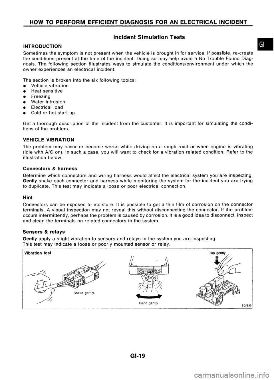
VEHICLE VIBRATION
The problem mayoccur orbecome worsewhiledriving onarough roadorwhen engine isvibrating
(idle with
AIC
on). Insuch acase, youwillwant tocheck foravibration relatedcondition. Refertothe
illustration below.
Connectors
&
harness
Determine whichconnectors andwiring harness wouldaffecttheelectrical systemyouareinspecting.
Gently
shakeeachconnector andharness whilemonitoring thesystem forthe incident youaretrying
to duplicate. Thistestmay indicate aloose orpoor electrical connection.
Hint
Connectors canbeexposed tomoisture. Itis possible toget athin film ofcorrosion onthe connector
terminals. Avisual inspection maynotreveal thiswithout disconnecting theconnector. Ifthe problem
occurs intermittently, perhapstheproblem iscaused bycorrosion. Itis agood ideatodisconnect, inspect
and clean theterminals onrelated connectors inthe system.
Sensors
&
relays
Gently
applyaslight vibration tosensors andrelays inthe system youareinspecting.
This testmay indicate aloose orpoorly mounted sensororrelay.
•
Vibration test
Bendgently.
GI-19
Tap
gently.
8GI839
Page 1400 of 1701
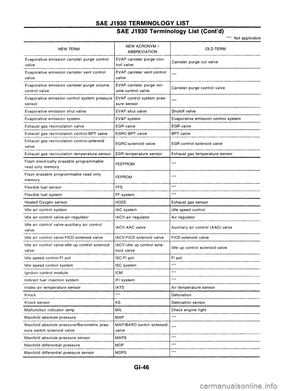
SAEJ1930 TERMINOLOGY LIST
SAE J1930 Terminology List(Cont'd)
***:
Not applicable
NEW TERM NEW
ACRONYM /
OLDTERM
ABBREVIATION
Evaporative emissioncanisterpurgecontrol EVAPcanister purgecon-
Canister purgecutvalve
valve trol
valve
Evaporative emissioncanisterventcontrol EVAPcanister ventcontrol
***
valve valve
Evaporative emissioncanisterpurgevolume EVAPcanister purgevol-
Canister purgecontrol valve
control valve ume
control valve
Evaporative emissioncontrolsystem pressure EVAP
control system pres-
***
sensor suresensor
Evaporative emissionshutvalve EVAP
shutvalve Shutoffvalve
Evaporative emissionsystem EVAPsystem Evaporative
emissioncontrolsystem
Exhaust gasrecirculation valve EGR
valve EGRvalve
Exhaust gasrecirculation control-BPTvalveEGRC-BPT valve BPT
valve
Exhaust gasrecirculation control-solenoid
EGRC-solenoidvalveEGR
control solenoid valve
valve
Exhaust gasrecirculation temperaturesensorEGRtemperature sensorExhaustgastemperature sensor
Flash electrically erasableprogrammable
FEEPROM
***
read onlymemory
Flash erasable programmable readonly
FEPROM
**.
memory
Flexible fuelsensor FFS
***
Flexible fuelsystem
FFsystem
***
Heated Oxygen sensor H02SExhaustgassensor
Idle aircontrol system lACsystem Idlespeed control
Idle aircontrol valve-air regulator IACV-airregulator Airregulator
Idle aircontrol valve-auxiliary aircontrol
IACV-AACvalve Auxiliaryaircontrol (AAC)valve
valve
Idle aircontrol valve-FICO solenoidvalve
IACV-FICDsolenoidvalve FICOsolenoid valve
Idle aircontrol valve-idle upcontrol solenoid IACV-idleupcontrol sole-
Idleupcontrol solenoid valve
valve noidvalve
Idle speed control-FI pot ISC-FIpot FIpot
Idle speed control system ISCsystem
***
Ignition controlmodule ICM
***
Indirect fuelinjection system IFIsystem
***
Intake airtemperature sensor IATS Airtemperature sensor
Knock
***
Detonation
Knock sensor
KSDetonation
sensor
Malfunction indicatorlamp MIL
Checkengine light
Manifold absolutepressure MAP
***
Manifold absolutepressure/Barometric pres-MAP/BARO switchsolenoid
***
sure switch solenoid valve valve
Manifold absolutepressure sensor MAPS
**.
Manifold differential pressure MOP
***
Manifold differential pressuresensor MOPS
***
GI-46
Page 1491 of 1701
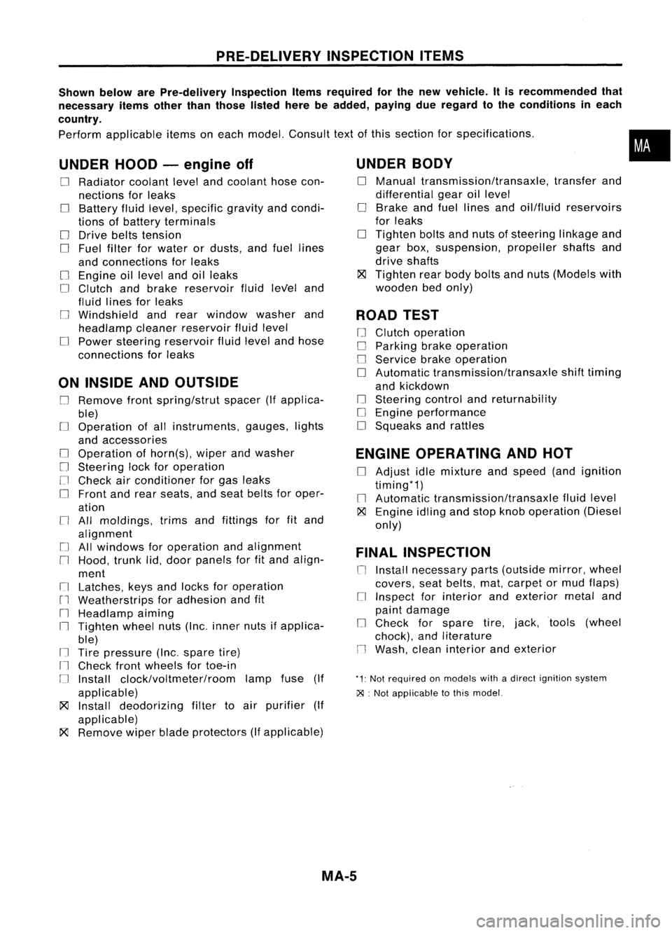
PRE-DELIVERYINSPECTIONITEMS
Shown belowarePre-delivery InspectionItemsrequired forthe new vehicle. Itis recommended that
necessary itemsotherthanthose listedherebeadded, payingdueregard tothe conditions ineach
country.
Perform applicable itemsoneach model. Consult textofthis section forspecifications .
UNDER HOOD-engine off
o
Radiator coolantlevelandcoolant hosecon-
nections forleaks
o
Battery fluidlevel, specific gravityandcondi-
tions ofbattery terminals
o
Drive beltstension
D
Fuel filter forwater ordusts, andfuel lines
and connections forleaks
[] Engine oillevel andoilleaks
D
Clutch andbrake reservoir fluidlevel and
fluid lines forleaks
o
Windshield andrear window washerand
headlamp cleanerreservoir fluidlevel
D
Power steering reservoir fluidlevel andhose
connections forleaks
ON INSIDE ANDOUTSIDE
D
Remove frontspring/strut spacer(Ifapplica-
ble)
D
Operation ofall instruments, gauges,lights
and accessories
o
Operation ofhorn(s), wiperandwasher
[] Steering lockforoperation
[] Check airconditioner forgas leaks
o
Front andrear seats, andseat belts foroper-
ation
n
All moldings, trimsandfittings forfitand
alignment
[J
Allwindows foroperation andalignment
n
Hood, trunklid,door panels forfitand align-
ment
[1
Latches, keysandlocks foroperation
rl
Weatherstrips foradhesion andfit
[l
Headlamp aiming
I~ Tighten wheelnuts(Inc. inner nutsifapplica-
ble)
IJ Tire pressure (Inc.spare tire)
Il
Check frontwheels fortoe-in
IJ Install clock/voltmeter/room lampfuse(If
applicable)
~ Install deodorizing filtertoair purifier (If
applicable)
~ Remove wiperbladeprotectors (Ifapplicable)
UNDER
BODY
o
Manual transmission/transaxle, transferand
differential gearoillevel
D
Brake andfuel lines andoil/fluid reservoirs
for leaks
D
Tighten boltsandnuts ofsteering linkageand
gear box,suspension, propellershaftsand
drive shafts
~ Tighten rearbody boltsandnuts (Models with
wooden bedonly)
ROAD TEST
D
Clutch operation
D
Parking brakeoperation
[J
Service brakeoperation
D
Automatic transmission/transaxle shifttiming
and kickdown
[] Steering controlandreturnability
o
Engine performance
D
Squeaks andrattles
ENGINE OPERATING ANDHOT
D
Adjust idlemixture andspeed (andignition
timing*1)
n
Automatic transmission/transaxle fluidlevel
~ Engine idlingandstop knob operation (Diesel
only)
FINAL INSPECTION
n
Install necessary parts(outside mirror,wheel
covers, seatbelts, mat,carpet ormud flaps)
[1
Inspect forinterior andexterior metaland
paint damage
[] Check forspare tire,jack, tools (wheel
chock), andliterature
n
Wash, cleaninterior andexterior
"1: Not required onmodels withadirect ignition system
~ :Not appiicable tothis model.
•
MA-5
Page 1492 of 1701
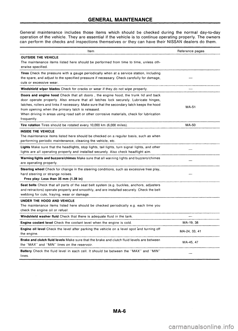
GENERALMAINTENANCE
General maintenance includesthoseitemswhich should bechecked duringthenormal day-to-day
operation ofthe vehicle. Theyareessential ifthe vehicle isto continue operating properly.Theowners
can perform thechecks andinspections themselves orthey canhave theirNISSAN dealersdothem.
Item
OUTSIDE THEVEHICLE
The maintenance itemslistedhereshould beperformed fromtimetotime, unless oth-
erwise specified.
Tires
Check thepressure withagauge periodically whenataservice station, including
the spare, andadjust tothe specified pressureifnecessary. Checkcarefully fordamage,
cuts orexcessive wear.
Windshield wiperblades
Checkforcracks orwear ifthey donot wipe properly.
Doors andengine hood
Check thatalldoors, theengine hood,thetrunk lidand back
door operate properly. Alsoensure thatalllatches locksecurely. Lubricate hinges,
latches, rollersandlinks ifnecessary. Makesurethatthesecondary latchkeeps thehood
from opening whentheprimary latchisreleased.
When driving inareas usingroadsaltorother corrosive materials, checkforlubrication
frequently.
Tire rotation
Tiresshould berotated every
10,000
km
(6,000
miles).
INSIDE THEVEHICLE
The maintenance itemslistedhereshould bechecked onaregular basis,suchaswhen
performing periodicmaintenance, cleaningthevehicle, etc.
Lights
Makesurethattheheadlights, stoplights, taillights, turnsignal lights,andother
lights arealloperating properlyandinstalled securely. Alsocheck headlight aim.
Warning lightsandbuzzers/chimes
Makesurethatallwarning lightsandbuzzers/chimes
are operating properly.
Steering wheel
Check forchange inthe steering conditions, suchasexcessive freeplay,
hard steering orstrange noises.
Free play: Lessthan35mm (1.38 in)
Seat belts
Check thatallparts ofthe seat beltsystem (e.g.buckles, anchors, adjusters
and retractors) operateproperly andsmoothly, andareinstalled securely. Checkthebelt
webbing forcuts, fraying, wearordamage.
UNDER THEHOOD ANDVEHICLE
The maintenance itemslisted hereshould bechecked periodically e.g.each timeyou
check theengine oilorrefuel.
Windshield washerfluid
Check thatthere isadequate fluidinthe tank.
Engine coolant level
Check thecoolant levelwhen theengine iscold.
Engine oillevel
Check thelevel afterparking thevehicle onalevel spotandturning off
the engine.
Brake andclutch fluidlevels
Makesurethatthebrake andclutch fluidlevels arebetween
the "MAX" and"MIN" linesonthe reservoir.
Battery
Checkthefluid level ineach cell.Itshould bebetween the"MAX" and"MIN"
lines.
MA-6
Reference
pages
MA-51
MA-50
MA-19,38
MA-24, 33,41
MA-45,47
Page 1511 of 1701
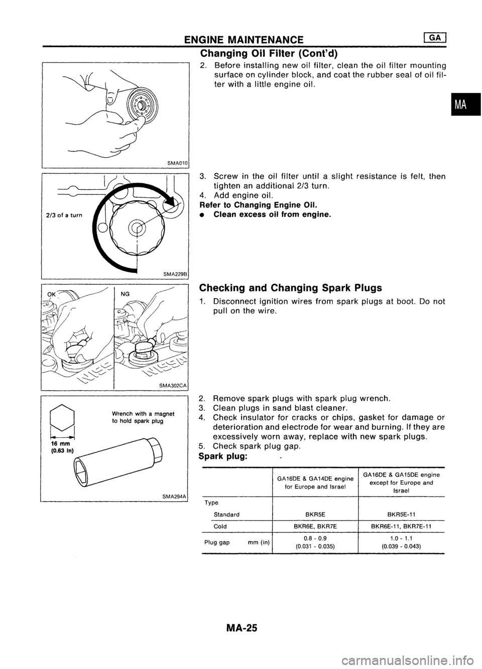
ENGINEMAINTENANCE ~
Changing OilFilter (Cont'd)
2. Before installing newoilfilter, clean theoilfilter mounting
surface oncylinder block,andcoat therubber sealofoil fil-
ter with alittle engine oil.
SMA010
•
2/3 ofaturn
g 16
mm
(0.63 In) SMA302CA
Wrench withamagnet
to hold spark plug
SMA294A
3.
Screw inthe oilfilter untilaslight resistance isfelt, then
tighten anadditional 2/3turn.
4. Add engine oil.
Refer toChanging EngineOil.
• Clean excess oilfrom engine.
Checking andChanging SparkPlugs
1. Disconnect ignitionwiresfromspark plugsatboot. Donot
pull onthe wire.
2. Remove sparkplugswithspark plugwrench.
3. Clean plugsinsand blastcleaner.
4. Check insulator forcracks orchips, gasket fordamage or
deterioration andelectrode forwear andburning. Ifthey are
excessively wornaway, replace withnewspark plugs.
5. Check sparkpluggap.
Spark plug:
GA16DE&GA14DE engine GA16DE
&GA15DE engine
for Europe andIsrael except
forEurope and
Israel
Type Standard BKR5E
BKR5E-11
Cold BKR6E,BKR7E BKR6E-11,
BKR7E-11
Plug gap mm(in) 0.8
-0.9 1.0-1.1
(0.031 -0.035) (0.039-0.043)
MA-25