1995 NISSAN ALMERA N15 diagram
[x] Cancel search: diagramPage 1365 of 1701
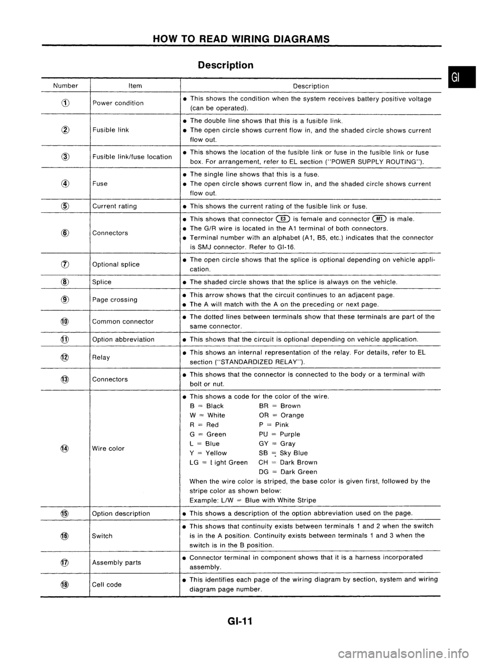
HOWTOREAD WIRING DIAGRAMS
Description
Number Item Description
CD
Power
condition •
This shows thecondition whenthesystem receives batterypositive voltage
(can beoperated) .
• The double lineshows thatthisisafusible link.
@
Fusiblelink
•The open circle shows current flowin,and theshaded circleshows current
flow out.
link/fuse location •
This shows thelocation ofthe fusible linkorfuse inthe fusible linkorfuse
box. Forarrangement, refertoEL section ("POWER SUPPLYROUTING") .
• The single lineshows thatthisisafuse.
@
Fuse
•The open circle shows current flowin,and theshaded circleshows current
flow out.
CID
Current
rating
•This shows thecurrent ratingofthe fusible linkorfuse .
• This shows thatconnector
@)
isfemale andconnector
@
ismale .
@
Connectors •
The G/R wire islocated inthe A1 terminal ofboth connectors.
• Terminal numberwithanalphabet (A1, B5, etc.) indicates thattheconnector
is SMJ connector. RefertoGI-16 .
rJ)
Optionalsplice •
The open circle shows thatthesplice isoptional depending onvehicle appli-
cation.
@
Splice •The shaded circleshows thatthesplice isalways onthe vehicle.
@
Page
crossing •
This arrow shows thatthecircuit continues toan adjacent page.
• The Awill match withtheAon the preceding ornext page .
@)
Commonconnector •
The dotted linesbetween terminals showthatthese terminals arepart ofthe
same connector.
@
Option
abbreviation •This shows thatthecircuit isoptional depending onvehicle application.
@
Relay •
This shows aninternal representation ofthe relay. Fordetails, refertoEL
section ("STANDARDIZED RELAY").
@
Connectors •
This shows thattheconnector isconnected tothe body oraterminal with
bolt ornut.
• This shows acode forthe color ofthe wire.
B
=
Black BR
=
Brown
W
=
White OR
=
Orange
R
=
Red P
=
Pink
G
=
Green PU
=
Purple
@
Wire
color L
=
Blue GY
=
Gray
Y
=
Yellow SB
=:
Sky Blue
LG
=
Light Green CH
=
Dark Brown
DG
=
Dark Green
When thewire color isstriped, thebase color isgiven first,followed bythe
stripe colorasshown below:
Example: LlW
=
Blue withWhite Stripe
@
Optiondescription •
This shows adescription ofthe option abbreviation usedonthe page.
• This shows thatcontinuity existsbetween terminals 1and 2when theswitch
@)
Switch is
inthe Aposition. Continuity existsbetween terminals 1and 3when the
switch isinthe Bposition .
@
Assembly
parts •
Connector terminalincomponent showsthatitis aharness incorporated
assembly .
@
Cell
code •
This identifies eachpage ofthe wiring diagram bysection, systemandwiring
diagram pagenumber.
GI-11
•
Page 1366 of 1701
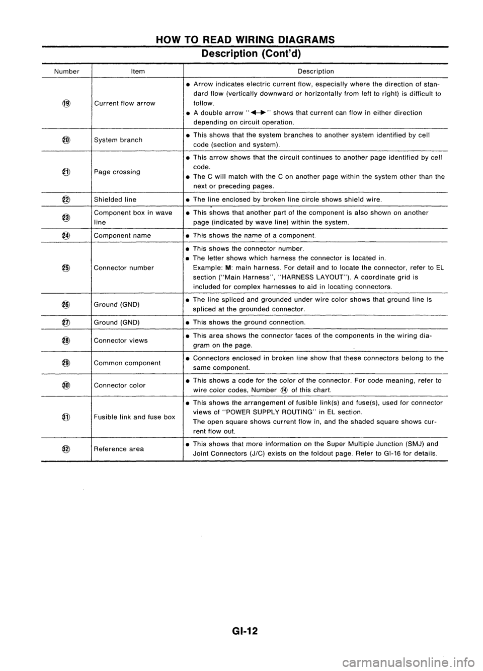
HOWTOREAD WIRING DIAGRAMS
Description (Cont'd)
Number Item Description
• Arrow indicates electriccurrentflow,especially wherethedirection ofstan-
dard flow(vertically downward orhorizontally fromlefttoright) isdifficult to
@)
Current
flowarrow follow.
• Adouble arrow" ...."shows thatcurrent canflow ineither direction
depending oncircuit operation .
@)
System
branch •
This shows thatthesystem branches toanother systemidentified bycell
code (section andsystem) .
• This arrow shows thatthecircuit continues toanother pageidentified bycell
@
code.
Page crossing
•The Cwill match withtheCon another pagewithin thesystem otherthanthe
next orpreceding pages.
@
Shieldedline •
The lineenclosed bybroken linecircle shows shieldwire.
@)
Component
boxinwave •
This shows thatanother partofthe component isalso shown onanother
line page
(indicated bywave line)within thesystem.
@
Component
name •This shows thename ofacomponent.
• This shows theconnector number.
• The letter shows whichharness theconnector islocated in.
@)
Connector
number Example:
M:main harness. Fordetail andtolocate theconnector, refertoEL
section ("MainHarness", "HARNESS LAYOUT").Acoordinate gridis
included forcomplex harnesses toaid inlocating connectors .
@
Ground
(GND) •
The linespliced andgrounded underwirecolor shows thatground lineis
spliced atthe grounded connector.
@
Ground
(GND) •
This shows theground connection.
@)
Connector
views •
This area shows theconnector facesofthe components inthe wiring dia-
gram onthe page .
@)
Common
component •
Connectors enclosedinbroken lineshow thatthese connectors belongtothe
same component.
@l
Connector
color •
This shows acode forthe color ofthe connector. Forcode meaning, referto
wire color codes, Number
@
ofthis chart.
• This shows thearrangement offusible link(s)andfuse(s), usedforconnector
@
views
of"POWER SUPPLYROUTING" inEL section.
Fusible linkand fuse box
Theopen square showscurrent flowin,and theshaded squareshowscur-
rent flow out.
@
Reference
area •
This shows thatmore information onthe Super Multiple Junction (SMJ)and
Joint Connectors
(J/C)
exists onthe foldout page.RefertoGI-16 fordetails.
GI-12
Page 1367 of 1701
HOWTOREAD WIRING DIAGRAMS
Description (Cont'd)
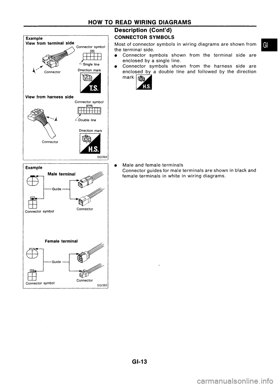
CONNECTOR SYMBOLS
Example
View fromterminal side
Connector symbol
~
Direction mark
[:it
Most
ofconnector symbolsinwiring diagrams areshown from
the terminal side.
• Connector symbolsshownfromtheterminal sideare
enclosed byasingle line.
• Connector symbolsshownfromtheharness sideare
enclosed byadouble lineand followed bythe direction
mark~
•
Direction mark
lit
Connector
View
fromharness side
Connector symbol
~I
8GI364
Male termlnar ~
G'id'V
Example
Connector symbol Connector •
Male
andfemale terminals
Connector guidesformale terminals areshown inblack and
female terminals inwhite inwiring diagrams.
Female terminal
Guide
Connector symbol Connector
8GI363
GI-13
Page 1368 of 1701
Normallyopen
HOW
TOREAD WIRING DIAGRAMS
Description (Cont'd)
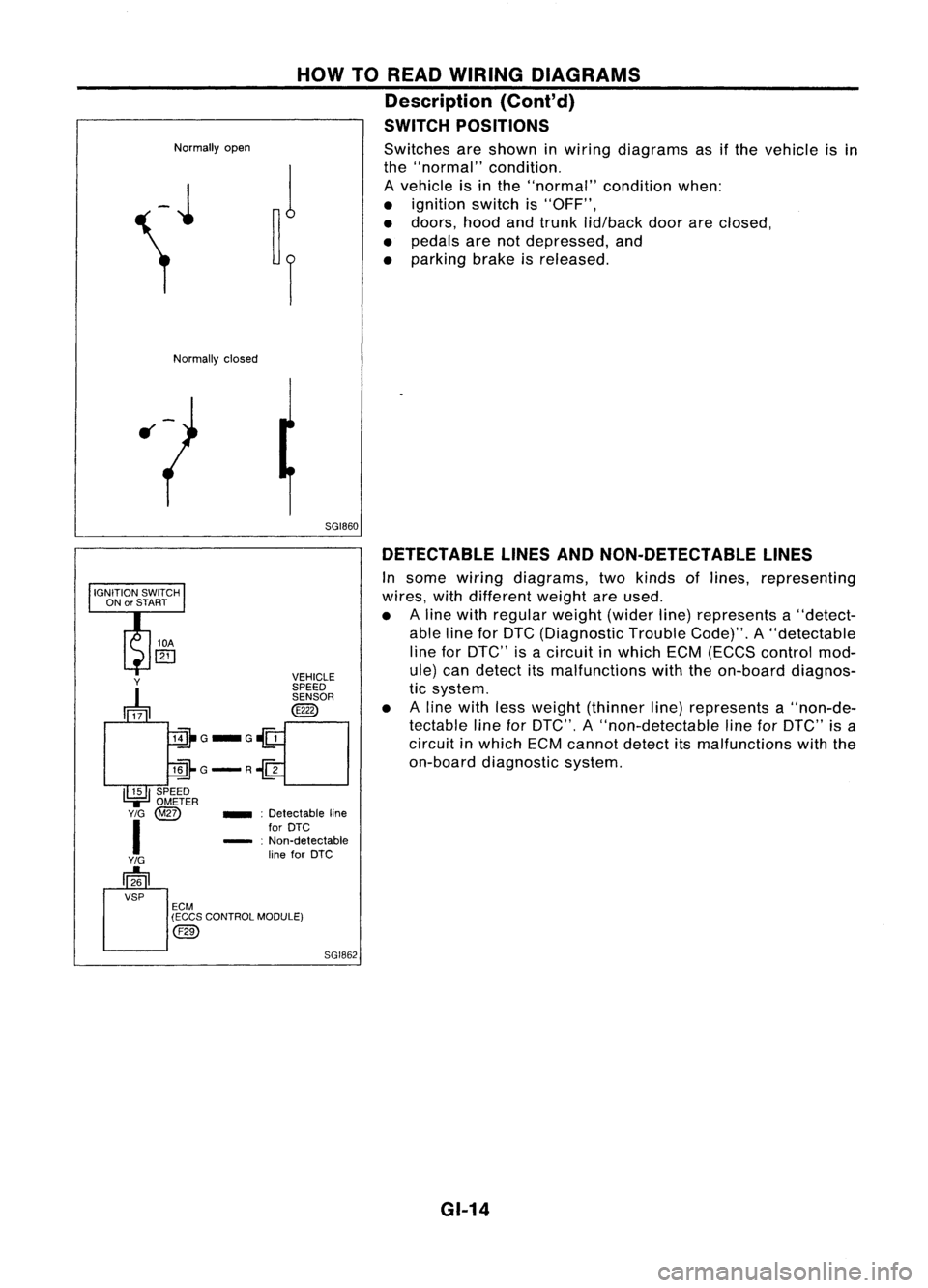
SWITCH POSITIONS
Switches areshown inwiring diagrams asifthe vehicle isin
the "normal" condition.
A vehicle isin the "normal" conditionwhen:
• ignition switchis"OFF",
• doors, hoodandtrunk lid/back doorareclosed,
• pedals arenotdepressed, and
• parking brakeisreleased.
Normally closed
5GI860DETECTABLE LINESANDNON-DETECTABLE LINES
In some wiring diagrams, twokinds oflines, representing
wires, withdifferent weightareused.
• Aline with regular weight(widerline)represents a"detect-
able lineforDTC (Diagnostic TroubleCode)".A"detectable
line forDTC" isacircuit inwhich ECM(ECCS control mod-
ule) candetect itsmalfunctions withtheon-board diagnos-
tic system.
• Aline with lessweight (thinner line)represents a"non-de-
tectable lineforDTC", A"non-detectable lineforDTC" isa
circuit inwhich ECMcannot detectitsmalfunctions withthe
on-board diagnostic system.
SGI862
_
:Detectable line
for DTC
- :Non-detectable
line forDTC
Y
~ VEHICLE
SPEED SENSOR
@
lill-G_G~
llli-G-R~
I~I
SPEED
.,=
OMETER
Y/G
@Z)
I
Y/G
[]26
VSP ECM
(ECCS CONTROL MODULE)
@)
GI-14
Page 1369 of 1701
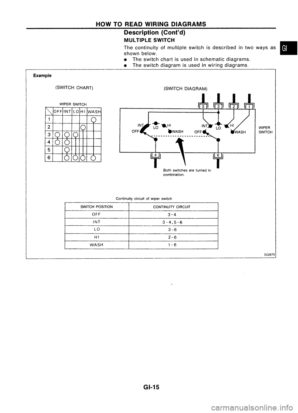
Example(SWITCHCHART)
WIPER SWITCH HOW
TOREAD WIRING DIAGRAMS
Description (Cont'd)
MULTIPLE SWITCH
The continuity ofmultiple switchisdescribed intwo ways as
shown below.
• The switch chartisused inschematic diagrams.
• The switch diagram isused inwiring diagrams.
WIPERSWITCH
f' f
80th switches areturned in
combination.
Continuity circuitofwiper switch
•
SWITCH POSITION
CONTINUITYCIRCUIT
OFF
3-4
INT
3-4,5-6
LO
3-6
HI
2-6
WASH
1-6
SGI875
GI-15
Page 1370 of 1701
HOWTOREAD WIRING DIAGRAMS
Description (Cont'd)
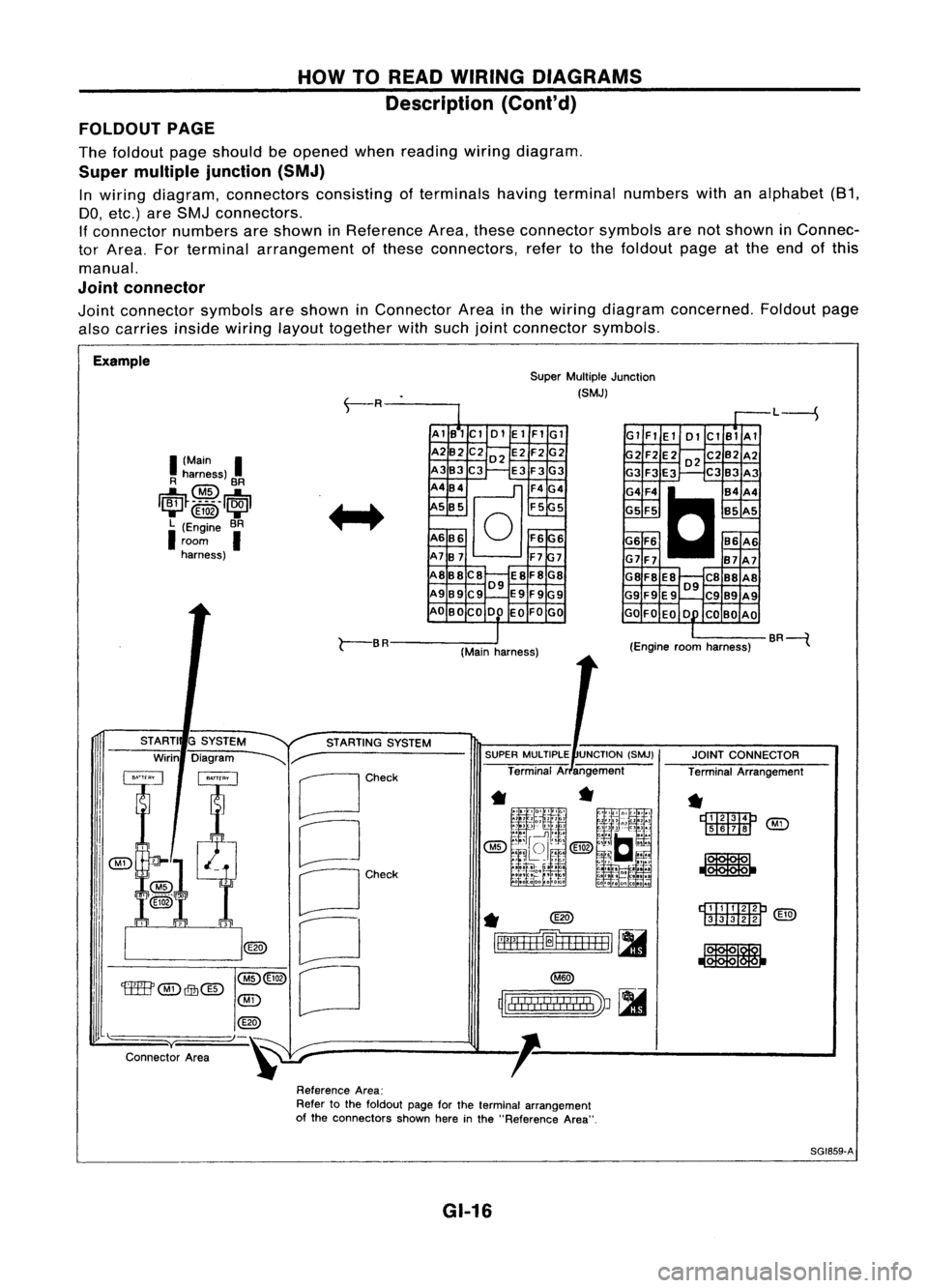
FOLDOUT PAGE
The foldout pageshould beopened whenreading wiringdiagram.
Super multiple junction (SMJ)
In wiring diagram, connectors consistingofterminals havingterminal numbers withanalphabet (81,
DO, etc.) areSMJ connectors.
If connector numbersareshown inReference Area,these connector symbolsarenotshown inConnec-
tor Area. Forterminal arrangement ofthese connectors, refertothe foldout pageatthe end ofthis
manual.
Joint connector
Joint connector symbolsareshown inConnector Areainthe wiring diagram concerned. Foldoutpage
also carries
insidewiring
layouttogether withsuch jointconnector symbols.
Example SuperMultiple Junction
(SMJ)
L----S
I
(Main
I
R harness)
@
BR
1~~_~_5 __
1~1
....... @ID .......
L (Engine BR
I
room
I
harness) AlB1Cl
01ElFIGl
A2B2 C202 E2F2G2
A3B3C3 E3F3G3
A4B4
@]
F4G4
5 B5 F55
A6B6
0
F6G6
A7B7 F77
A8B8C8 E8F8G8
09
A989C9 E9F9G9
AO BOCO DO EOFOGO Gl
FlEl 01ClBlAl
2F2E202C2B2A2
G3 F3E3 C3B3 A3
G4F4
C
B4A4
G5 F5 B5A5
G6 F6 86A6
G7F7 B7A7
G8F8 E8 C888A8
09
G9 F9E9 C989A9
GO FOEO 0 COBO AO
r-
BR
(Mainharness) (Engine
roomharness) BR----{
rDI.TI:IImP
[ill![ill]
@g)
JOINT
CONNECTOR
Terminal Arrangement
*
r::t::rrm::m:J
'M'i'
[ill]II!J ~
*
~
rll"
!! !
I
!
I II
!I
I
'J ~
~lllll!I!!lIllbV ~
SUPER
MULTIPLE UNCTION(SMJ)
Terminal Arangement
*
@)
~=fH+H=1
[II
STARTING
SYSTEM
G
SYSTEM
Diagram
~r-
[Jcheck
CJ
OCh~'
o
[J
STARTI
Wirin
@(3)
'tffB'
@)
Qfu@
@)
@
"-)-~
y
Connector Area
ReferenceArea:
Refer tothe foldout pageforthe terminal arrangement
of the connectors shownhereinthe "Reference Area".
SG1859-A
GI-16
Page 1371 of 1701
HOWTOREAD WIRING DIAGRAMS
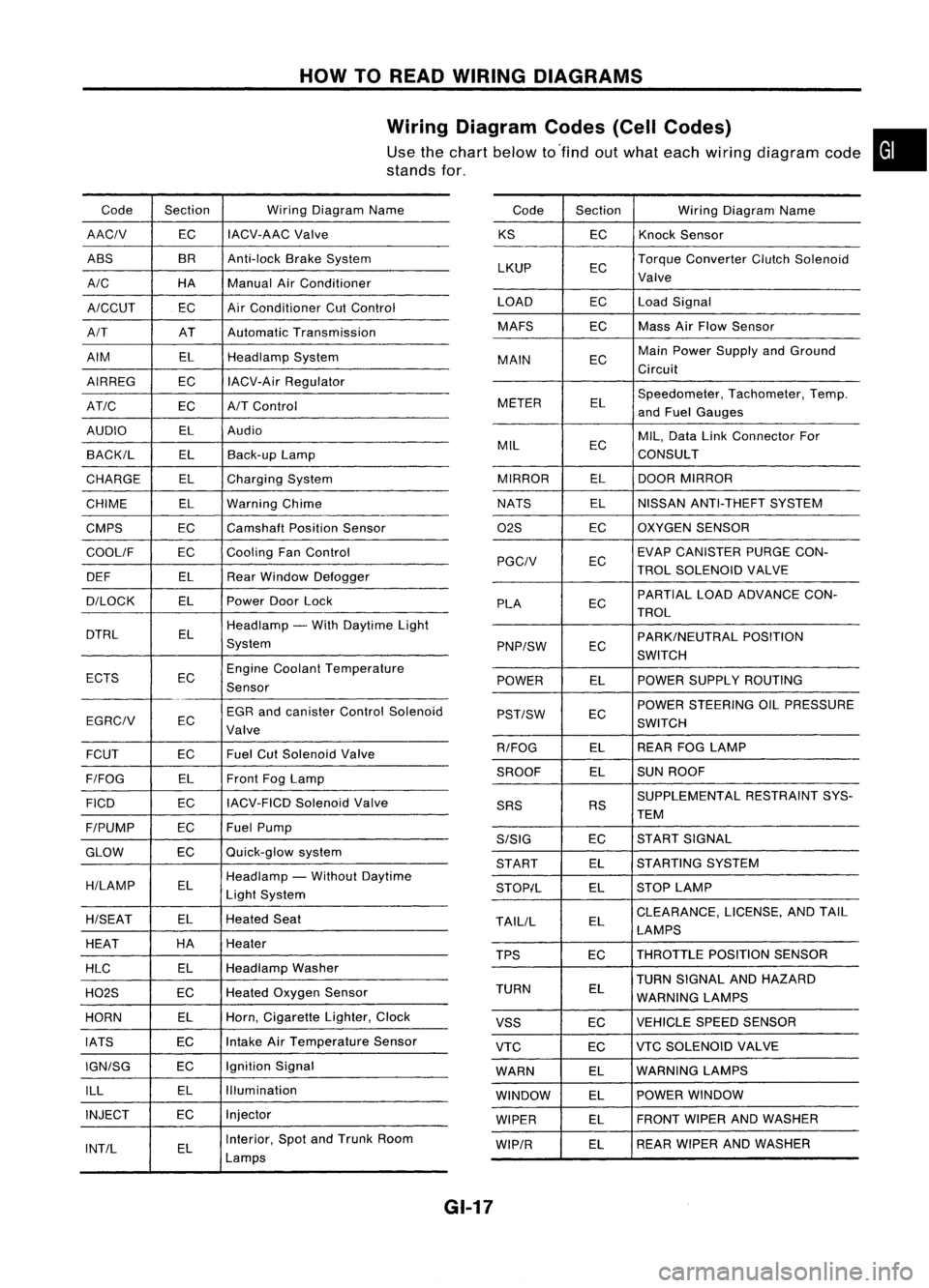
Wiring Diagram Codes(CellCodes)
Use thechart below to'find outwhat each wiring diagram code•
stands for,
Code Section WiringDiagram Name
AACIV ECIACV-AAC
Valve
ABS BR
Anti-lock BrakeSystem
A/C HAManualAirConditioner
A/CCUT ECAir
Conditioner CutControl
A/T ATAutomatic Transmission
AIM ELHeadlamp System
AIRREG ECIACV-Air Regulator
AT/C ECA/TControl
AUDIO ELAudio
BACK/L ELBack-up Lamp
CHARGE ELCharging System
CHIME ELWarning Chime
CMPS EC
Camshaft PositionSensor
COOllF ECCooling
FanControl
DEF ELRearWindow Defogger
D/LOCK ELPowerDoorLock
DTRL ELHeadlamp
-With Daytime Light
System
ECTS ECEngine
Coolant Temperature
Sensor
EGR andcanister ControlSolenoid
EGRCIV EC
Valve
FCUT ECFuel
CutSolenoid Valve
F/FOG ELFront
FogLamp
FICO ECIACV-FICD
SolenoidValve
F/PUMP ECFuel
Pump
GLOW ECQuick-glow
system
H/LAMP ELHeadlamp
-Without Daytime
Light System
H/SEAT ELHeated
Seat
HEAT HA
Heater
HLC ELHeadlamp
Washer
H02S ECHeated
Oxygen Sensor
HORN ELHorn,
Cigarette Lighter,Clock
IATS ECIntake
AirTemperature Sensor
IGN/SG ECIgnition
Signal
ILL ELIllumination
INJECT ECInjector
INT/L ELInterior,
SpotandTrunk Room
Lamps Code
Section WiringDiagram Name
KS ECKnock
Sensor
LKUP ECTorque
Converter ClutchSolenoid
Valve
LOAD ECLoadSignal
MAFS ECMass
AirFlow Sensor
MAIN ECMain
Power Supply andGround
Circuit
METER ELSpeedometer,
Tachometer,Temp.
and Fuel Gauges
MIL ECMIL,
Data LinkConnector For
CONSULT
MIRROR ELDOOR
MIRROR
NATS ELNISSAN
ANTI-THEFT SYSTEM
02S ECOXYGEN
SENSOR
EC EVAP
CANISTER PURGECON-
PGCIV TROLSOLENOID VALVE
PLA ECPARTIAL
LOADADVANCE CON-
TROL
EC PARK/NEUTRAL
POSITION
PNP/SW SWITCH
POWER ELPOWER
SUPPLY ROUTING
POWER STEERING OILPRESSURE
PST/SW EC
SWITCH
R/FOG ELREAR
FOGLAMP
SROOF ELSUN
ROOF
SUPPLEMENTAL RESTRAINTSYS-
SRS RS
TEM
S/SIG ECST
ART SIGNAL
START ELSTARTING
SYSTEM
STOP/L ELSTOP
LAMP
TAllIL ELCLEARANCE,
LICENSE,ANDTAIL
LAMPS
TPS ECTHROTTLE
POSITIONSENSOR
TURN SIGNAL ANDHAZARD
TURN EL
WARNING LAMPS
VSS ECVEHICLE
SPEEDSENSOR
VTC ECVTC
SOLENOID VALVE
WARN ELWARNING
LAMPS
WINDOW ELPOWER
WINDOW
WIPER ELFRONT
WIPERANDWASHER
WIP/R ELREAR
WIPER ANDWASHER
GI-17
Page 1375 of 1701
HOWTOPERFORM EFFICIENT DIAGNOSIS FORANELECTRICAL INCIDENT
Incident Simulation Tests(Cont'd)
Engine compartment
There areseveral reasons avehicle orengine vibration could•
cause anelectrical complaint. Someofthe things tocheck for
are:
• Connectors notfully seated.
• Wiring harness notlong enough andisbeing stressed due
to engine vibrations orrocking.
• Wires laying across brackets ormoving components.
• Loose, dirtyorcorroded groundwires.
• Wires routed tooclose tohot components.
To inspect components underthehood, startbyverifying the
integrity ofground connections. (RefertoGROUND INSPEC-
TION described later.)Firstcheck thatthesystem isproperly
grounded. Thencheck forloose connection by
gently shaking
the wiring orcomponents aspreviously explained. Usingthe
wiring diagrams inspectthewiring forcontinuity.
Behind theinstrument panel
An improperly routedorimproperly clampedharnesscan
become pinchedduringaccessory installation. Vehiclevibra-
tion canaggravate aharness whichisrouted alongabracket
or near ascrew.
Under seating areas
An unclamped orloose harness cancause wiring tobe pinched
by seat components (suchasslide guides) duringvehicle vibra-
tion. Ifthe wiring runsunder seating areas,inspect wirerout-
ing forpossible damageorpinching.
Heating test
Do not heat above 60°C(140°F).
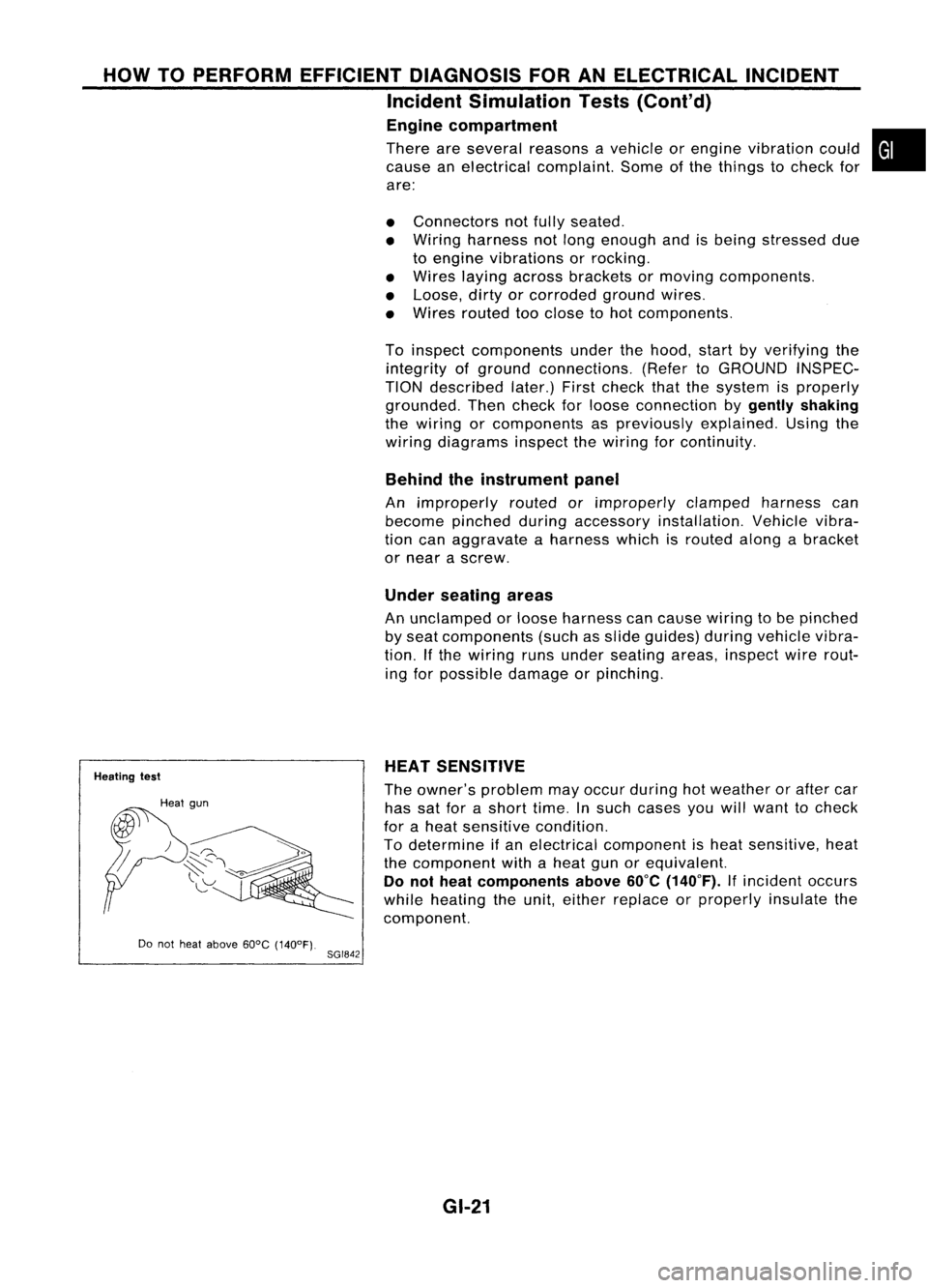
8GI842 HEAT
SENSITIVE
The owner's problem mayoccur during hotweather orafter car
has satforashort time.Insuch cases youwillwant tocheck
for aheat sensitive condition.
To determine ifan electrical component isheat sensitive, heat
the component withaheat gunorequivalent.
Do not heat components above
60°C
(140°F).
Ifincident occurs
while heating theunit, either replace orproperly insulatethe
component.
GI-21