Page 1383 of 1701

HOWTOFOLLOW FLOWCHART INTROUBLE DIAGNOSES
NOTICE
The flow chart indicates workprocedures requiredtodiagnose
problems effectively. Observethefollowing instructions before
diagnosing.
1) Use theflow chart afterlocating probable causesofaprob-
lem following the"Preliminary Check",the"Symptom
Chart" orthe "Work Flow".
2) After repairs, re-check thattheproblem hasbeen com-
pletely eliminated.
3) Refer toComponent PartsandHarness Connector Location
for the Systems described ineach section foridentificationl
location ofcomponents andharness connectors.
4) Refer tothe Circuit Diagram forQuick Pinpoint Check.
If you must check circuit continuity betweenharnesscon-
nectors inmore detail, suchaswhen asub-harness isused,
refer toWiring Diagram ineach individual sectionandHar-
ness Layout inEL section foridentification ofharness con-
nectors.
5) When checking circuitcontinuity, ignitionswitchshould be
"OFF" .
6) Before checking voltageatconnectors, checkbattery volt-
age.
7) After accomplishing theDiagnostic Procedures andElectri-
cal Components Inspection,makesurethatallharness con-
nectors arereconnected asthey were.
•
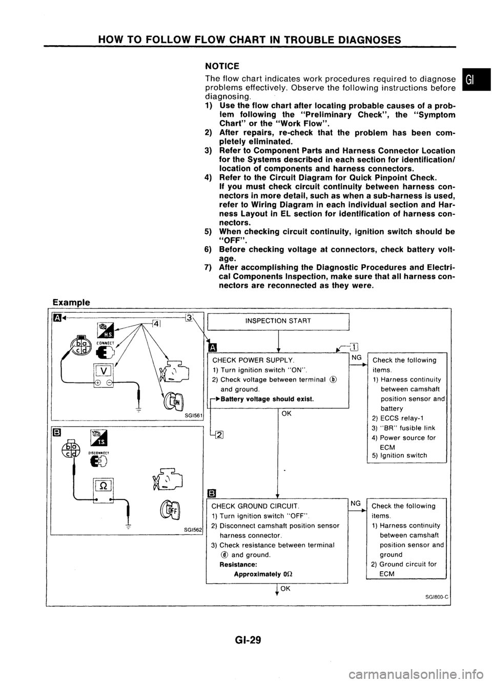
Example
m ..
-=-=~-----------~
~
~i5
[YJ
SGI561
~
OISCONNECT
18
SGI562
INSPECTION
START
CHECK POWER SUPPLY.
1) Turn ignition switch"ON".
2) Check voltage between terminal
@
and ground.
~Ba"ery voltageshouldexist.
OK
2
Ii)
CHECK GROUND CIRCUIT.
1) Turn ignition switch"OFF"
2) Disconnect camshaftpositionsensor
harness connector.
3) Check resistance betweenterminal
@
and ground.
Resistance: Approximately
on
OK
GI-29 NG
Check
thefollowing
items. 1) Harness continuity
between camshaft
position sensorand
battery
2) ECCS relay-1
3) "SR" fusible link
4) Power source for
ECM
5) Ignition switch
Check thefollowing
items. 1) Harness continuity
between camshaft
position sensorand
ground
2) Ground circuitfor
ECM
SG1800-C
Page 1403 of 1701

HEATER
&
AIR CONDITIONER
SECTION
HA
CONTENTS
When youread wiring diagrams:
• Read GIsection, "HOWTOREAD WIRING DIAGRAMS" .
• See ELsection, "POWER SUPPLYROUTING" forpower distribution circuit.
When youperform troublediagnoses, readGIsection, "HOWTOFOLLOW FLOWCHART
IN TROUBLE DIAGNOSES" and"HOW TOPERFORM EFFICIENT DIAGNOSIS FORAN
ELECTRICAL INCIDENT".
PRECAUTIONS
ANDPREPARATION 2
Supplemental RestraintSystem(SRS)"AIR
BAG" (DualAirBag System) 2
Supplemental RestraintSystem(SRS)"AIR
BAG", (Single AirBag System) 2
Precautions forWorking withHFC-134a (R-
134a) 3
General Refrigerant Precautions 3
Precautions forRefrigerant Connection 4
Precautions forServici ngCompressor. ..5
Special Service Tools 5
HFC-134a (R-134a)ServiceToolsand
Equipment. 6
Precautions forService Equipment 8
DESCRIPTION 10
Refrigeration Cycle .10
Component Layout 11
Discharge AirFlow 12
Control Operation 13
TROUBLE DIAGNOSES 14
Contents 14Wiring
Diagram -HEATER - 36
Wiring Diagram -
AIC - 38
SERVICE PROCEDURES 66
HFC-134a (R-134a)ServiceProcedure 66
Maintenance ofLubricant Quantityin
Compressor 68
Refrigerant Lines 70
Compressor Mounting 75
Belt Tension 76
Fast IdleControl Device(FICO) 76
Compressor -Model DKV-11D andDKV-14D
(ZEXEL make) 77
Compressor Clutch 77
Thermal Protector 80
Compressor -Model CR-14 (Calsonic make)80
Compressor Clutch ..80
Thermal Protector 82
Ventilation AirFilter 83
SERVICE DATAANDSPECIFICATIONS (SDS)84
General Specifications 84
Inspection andAdjustment 84
•
Page 1416 of 1701

TROUBLEDIAGNOSES
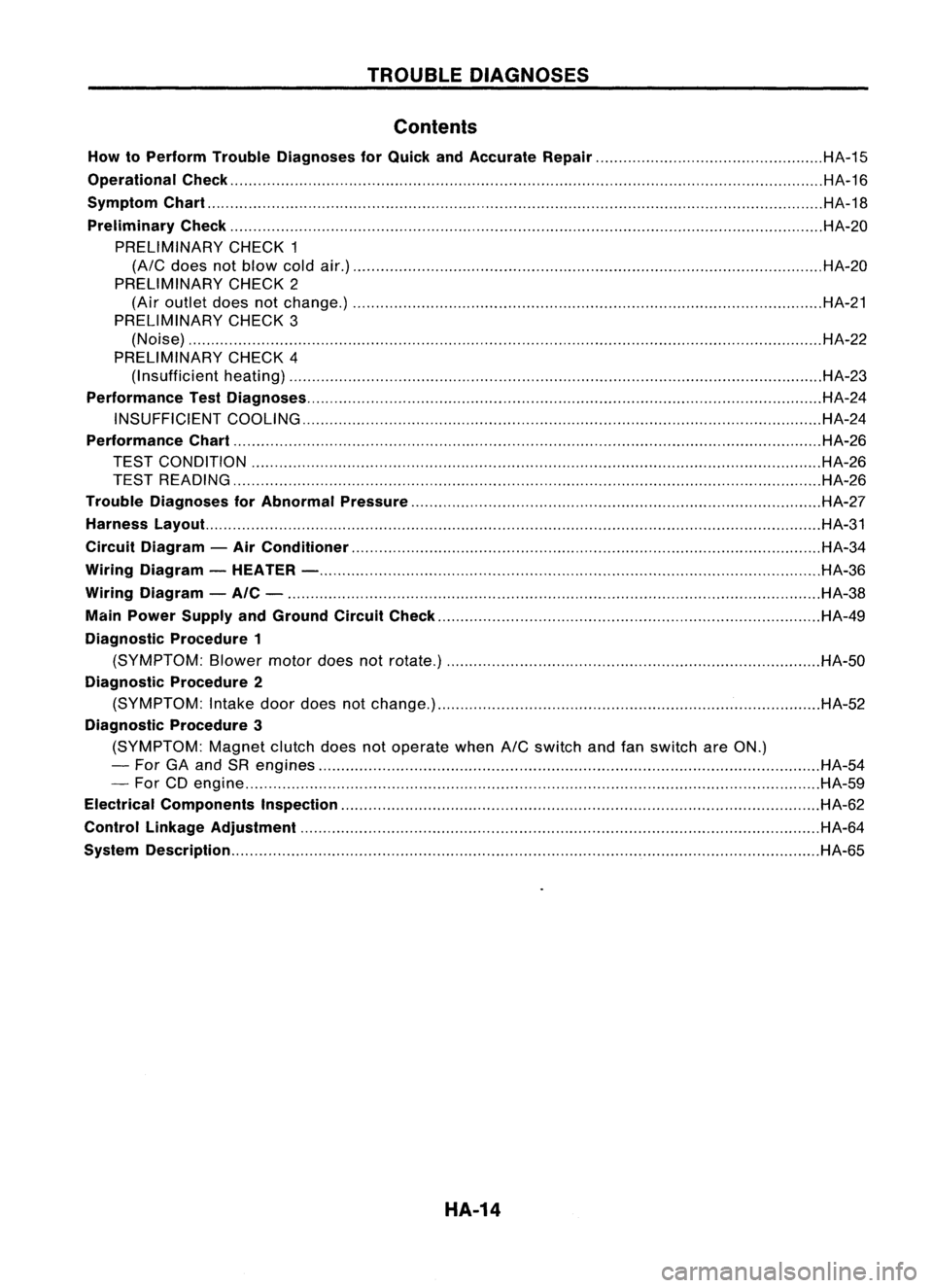
Contents
How toPerform TroubleDiagnoses forQuick andAccurate Repair HA-15
Operational Check HA-16
Symptom Chart HA-18
Preliminary Check HA-20
PRELIMINARY CHECK1
(A/C
does notblow coldair.) HA-20
PRELIMINARY CHECK2
(Air outlet doesnotchange.) HA-21
PRELIMINARY CHECK3
(Noise) HA-22
PRELIMINARY CHECK4
(I nsufficient heating) HA-23
Performance TestDiagnoses HA-24
INSUFFICIENT COOLING HA-24
Performance Chart HA-26
TEST CONDITION HA-26
TEST READING HA-26
Trouble Diagnoses forAbnormal Pressure HA-27
Harness Layout. HA-31
Circuit Diagram -Air Conditioner HA-34
Wiring Diagram -HEATER - HA-36
Wiring Diagram -AIC - HA-38
Main Power Supply andGround CircuitCheck HA-49
Diagnostic Procedure1
(SYMPTOM: Blowermotordoesnotrotate.) HA-50
Diagnostic Procedure2
(SYMPTOM: Intake doordoes notchange.) HA-52
Diagnostic Procedure3
(SYMPTOM: Magnetclutchdoesnotoperate when
A/C
switch andfanswitch areON.)
- For GAand SRengines HA-54
- For CDengine HA-59
Electrical Components Inspection HA-62
Control Linkage Adjustment HA-64
System Description HA-65
HA-14
Page 1417 of 1701
TROUBLEDIAGNOSES
How toPerform TroubleDiagnoses forQuick
and Accurate Repair
WORK FLOW
_________C_H_EI_K_I_N
I
+-1
Reference item
.--------------,
ELIMINATE GOODSYSTEM(S)/PART(S).
INVESTIGATE
IT-EMSYOUSHOULD CARRYOUT
RELATED TOEACH SYMPTOM.
CHECK MAINPOWER SUPPLY ANDGROUND CIR-
CUITS. LISTEN
TOCUSTOMER COMPLAINT ANDCONFIRM BY
PERFORMING OPERATIONAL CHECK. Operational
check
+-
(Refer toHA-16.)
Symptom Chart(Refer
to HA-18.)
Symptom Chart
+-
(Refer toHA-18.)
+-
Preliminary Check
(Refer toHA-20.)
+-
MainPower Supply and
Ground CircuitCheck
(Refer toHA-49.)
Harness layout(Referto
+-
HA-31.)
Malfunctioning
part(s)
Malfunctioning
harness( es)/
connector(s)
ELIMINATE
GOODPART(S)/HARNESS(ES)/
CONNECTOR(S) ELECTRICALLY.
•
Diagnostic Proce-
dure(s) (Referto
HA-50.)
• Circuit Diagram
(Refer toHA-34.)
NG
I
REPAIR. INSPECT
EACHCOM-
PONENT.
FINAL CHECK Electrical
Components
+-
Inspection
(Refer toHA-62.)
•
CHECK OUT
HA-15
Page 1436 of 1701
TROUBLEDIAGNOSES
Circuit Diagram -Air Conditioner
DUAL-PRESSURE
SWITCH
AIR
CONDITIONER
RELAY
THERMO
CONTROL
AMP.
IT
o
f-
U1
H
~
IT
W
I
f-
AIC
SWITCH
M
BLOWER
MOTOR
FAN
RESISTOR
GE
C
FAN SWITCH
OFF1234
GA
D
o
uo
HH
[LO
IZW
>w>
U..J....J
404
HUJ>
IT
o
..JI-
«u
~w
IT
I-
wo
IIT
f-(L
IT
o
U1
U1
W
IT
(L
~
o
u
RECIRCULA
nON
SWITCH
1
AIT models
MIT
models
For Europe andIsrael
Except
@
GA engine models
Except
f
or Europe, Israe 1and Austra 1ia
GA eng ine
f
or Europe, Israe1and Austra 1ia and SReng Ine
Except
@
LHD
AIT
models forEurope without daytIme lightsystem
Except
@
41.
@
44
@:
@:
@:
@:
@:
@:
@:
@:
:
@:
*1
To
illumination
system
HHA001
HA-34
Page 1437 of 1701
TROUBLEDIAGNOSES
Circuit Diagram -Air Conditioner (Cont'd)
I
I
I
I
I
I
I
I
I
I
I
I
I
I
I
I
I
I
I
I
I
I
I
I
I
I
I
I
I
---------,
M
COOLING COOLING
FAN FAN
MOTOR-l MOTOR-2
@ @
COOLING
FAN
RELAY-l
<{
-'
4541 *1119 10
ECM(ECCS
CONTROL
MODULE)
A
B
Z
LL
(!)[\J
ZI
HCI:
-10
01-
00
U::E
Z
LL
(!)
[\J
Z I
H
>-
-I
OZ-I
O
ULLCI:
(!)
~
Z I
H
>-
-I
OZ-I
O
ULLCI:
41119 10
ECM(ECCS
CONTROL
MODULE)
A
L ~
(SR20DE engine
AIT
models)
L
~
(GA engine except forAustralia
and SR20DE engine
MIT
models)
•
M
COOLING
FAN
RELAY-2
@
COOLING
FAN
MOTOR-2
@
COOLING
FAN
RELAY-l
COOLING COOLING
FAN FAN
MOTOR-l MOTOR-2
@
@
35 2115 13 14
ECMIECCS
CONTROL MODULE)
A
o
,
Z
I
LL
I
(!)(Tl
I
ZI
H>-
I
-I
,
0-1
ow
I
ucr
I
I
I
I
I
I
I
I
Z
I
I
LL
I
(!)(\J
I
ZI
I
HCI:
-10
I
OI-
I
00
U::E
I
I
I
I
I
I
I
I
I
I
I
Z
LL
(!)(\J
ZI
H>-
-I
0-1
ow
UCI:
Z
LL
(!) ....
ZI
H>-
-I
0-1
ow
UCI:
31 B9 10
ECM(ENGINE
CONTROL MODULE)
A
Z
LL
B
(!)~
ZI
HCI:
-10
01-
00
U::E
L
J
(C020 engIne) (GAI6DE
engIneforAustralIa)
HHA014
HA-35
Page 1438 of 1701
TROUBLEDIAGNOSES
Wiring Diagram -HEATER -
HA-HEATER-01
<0:
LHOmodels
Refer toEL-POWER.
(8):
RHOmodels
@:
ForEurope andIsrael
@:
Except@
t
LIB
~
~~~~ST""
L/W L/YL/R
.,--I-~r=t
r
RIG.
To
EL-m
t
L/WL/YL!R LIBRIG
I
:4
II
:31 12~1
Ii2'nJ n1=iI
FAN
SWITCH
@
ILL. ~
~ ~
B B
~ol __
1
I
I I
<
------.~o--l
JOINT
B CONNECTOR-4
1
Li t
J
Lt
1
B
{J
gj.
B~Next page
\~
~/
\~
~
~/
<0
FUSE
15A BLOCK
T
(JIB)
L..:..J ~
IN31
•
L!W L/W
L.l
I
L/W
~1
M
BLOWER
MOTOR
~
I!.j.JJ
LIB
~--------------------,
i~@~~:
I~W 2Wi
I I
I I
L
~
l1IillIITillIil
~
~P
Refer
tolast page
(Foldout page).
~
HHA012
HA-36
Page 1439 of 1701
TROUBLEDIAGNOSES
Wiring Diagram -HEATER -(Conl'd)
r-------------------,
1~ ~~)1
: (b)
@ :
L ~
•
Refer
tolast page
(Fo'ldout page).
HA-HEATER-02
(b):
LHDmodels
@:
RHOmodels
@: ForEurope andIsrae 1
@:
Except@
*1
(6)
GIS
ViS
*2
<0
G/Y,
@
Y/R
,
RECIRCULATION
SWITCH
~
Refer
toEL-POWER.
LG/R
ffi
INDICATOR
INTAKE
DOOR
MOTOR
~
L
FUSE
BLOCK
(JIB)
~
IN21
•
LG/R
7.5A
III
~B
I
~O
IGNITION
SWITCH
ON
EE
~~
~W
Preceding
~B
page ~
HHA013
HA-37