Page 688 of 1701
ON-VEHICLESERVICE
Front Wheel Alignment
Before checking frontwheel alignment, besure tomake apre-
liminary inspection (Unladen*).
*: Fuel, radiator coolantandengine oilfull. Spare tire,jack,
hand tools andmats indesignated positions.
SFA575B PRELIMINARY INSPECTION
1. Check tiresforwear andimproper inflation.
2. Check wheelrunout.
Wheel runout:
Refer toSOS (FA-30).
3. Check frontwheel bearings forlooseness.
4. Check frontsuspension forlooseness.
5. Check steering linkageforlooseness.
6. Check thatstruts workproperly.
7. Check vehicle posture (Unladen).
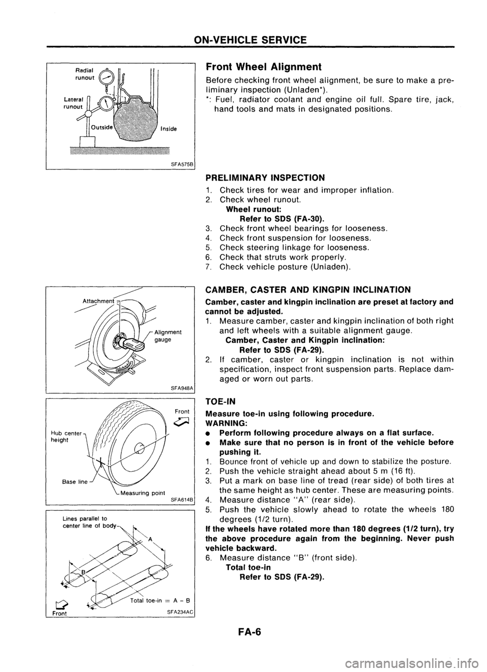
TOE-IN Measure toe-inusingfollowing procedure.
WARNING:
• Perform following procedure alwaysonaflat surface.
• Make surethatnoperson isin front ofthe vehicle before
pushing it.
1. Bounce frontofvehicle upand down tostabilize theposture.
2. Push thevehicle straight aheadabout5m (16 ft).
3. Put amark onbase lineoftread (rearside) ofboth tires at
the same height ashub center. Thesearemeasuring points.
4. Measure distance"A"(rear side).
5. Push thevehicle slowlyaheadtorotate thewheels 180
degrees (1/2turn).
If the wheels haverotated morethan180degrees
(112
turn), try
the above procedure againfromthebeginning. Neverpush
vehicle backward.
6. Measure distance"B"(front side).
Total toe-in
Refer toSOS (FA-29).
CAMBER,
CASTERANDKINGPIN INCLINATION
Camber, casterandkingpin inclination arepreset atfactory and
cannot beadjusted.
1. Measure camber,casterandkingpin inclination ofboth right
and leftwheels withasuitable alignment gauge.
Camber, CasterandKingpin inclination:
Refer toSOS (FA-29).
2. Ifcamber, casterorkingpin inclination isnot within
specification, inspectfrontsuspension parts.Replace dam-
aged orworn outparts.
Front
SFA948A
SFA614B
SFA234AC
Lines
parallel to
center lineofbody
Q
Front
Hub
center
height
FA-6
Page 706 of 1701
SEC.391.400.401
When installing rubberparts,finaltightening
must becarried outunder unladen condition'
with tires onground.
• Fuel, radiator coolanta'1dengine 011full.
Spare tire,Jack, hand toolsandmats In
designated positions.
@
~
L.~
(3.2-4.3, 23•31)
Front
CD
Spacer
@
Strut mounting insulator
@
Strut mounting insulator
bracket
@
Thrust bearing
@
Upper spring seat
@
Upper spring rubber seat
(J)
Bumper rubber
@
Coilspring
FRONT
SUSPENSION
@
Lower spring rubber seat
@)
Strut assembly
@
Suspension member
@
Stabilizer bar
@
Stabilizer clamp
@
Connecting rod
@
Transverse link
@
Compression rodclamp
@
Drive shaft
FA-24
~~
59.74
~~~.~ ::'.4:9- 54)
o
(2.5_3.0,
18 -22)
~
~~
~ ~
9=:
~~
-----J
/~18-24
1/ ~
(1.8.2.4,13.17)
~. @
&1
(@
~ J~!~5
(20-28, 145 •203)
~ 59•74 (6.0 -7.5, 43•54)
SFA624B
@
Knuckle
@
Cotter pin
@)
ABS sensor
@
Plain washer
@
Wheel bearing locknut
@
Insulator
@
Adjusting cap
@
Cotter pin
Page 707 of 1701
Suitable
bar
SFA610BFRONT
SUSPENSION
Coil Spring andStrut Assembly
REMOVAL ANDINSTALLATION
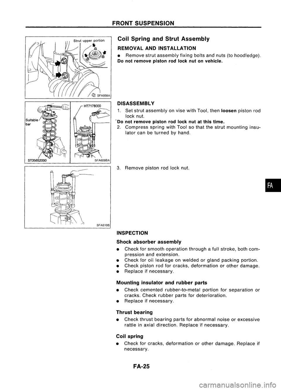
• Remove strutassembly fixingboltsandnuts (tohoodledge).
Do not remove pistonrodlock nutonvehicle.
DISASSEMBL Y
1. Set strut assembly onvise withTool, then
loosen
pistonrod
lock nut.
. Do not remove pistonrodlock nutatthis time.
2. Compress springwithTool sothat thestrut mounting insu-
lator canbeturned byhand.
3. Remove pistonrodlock nut.
INSPECTION
Shock absorber assembly
• Check forsmooth operation throughafull stroke, bothcom-
pression andextension.
• Check foroilleakage onwelded orgland packing portion.
• Check pistonrodforcracks, deformation orother damage.
• Replace ifnecessary.
Mounting insulatorandrubber parts
• Check cemented rubber-to-metal portionforseparation or
cracks. Checkrubber partsfordeterioration.
• Replace ifnecessary.
Thrust bearing
• Check thrustbearing partsforabnormal noiseorexcessive
rattle inaxial direction. Replaceifnecessary.
Coil spring
• Check forcracks, deformation orother damage. Replaceif
necessary.
FA-25
•
Page 708 of 1701
Front
Inside of
..-1'.
vehicle
L..y'
\
'
~Ud
Outside of
vehicle SFA508A
SFA957A
SFA625B FRONT
SUSPENSION
Coil Spring andStrut Assembly (Cont'd)
ASSEMBLY
• When installing coilspring onstrut, itmust bepositioned as
shown inthe figure atleft.
• When installing springseat,make surethatitis positioned
as shown.
Stabilizer Bar
REMOVAL ANDINSTALLATION
• Remove stabilizer bar.
• When installing stabilizer, makesurethatpaint markand
clamp faceintheir correct directions.
• When removing andinstalling stabilizer bar,fixportion
A.
FA-26
Page 709 of 1701
View
from
B FRONT
SUSPENSION
Stabilizer Bar(Cont'd)
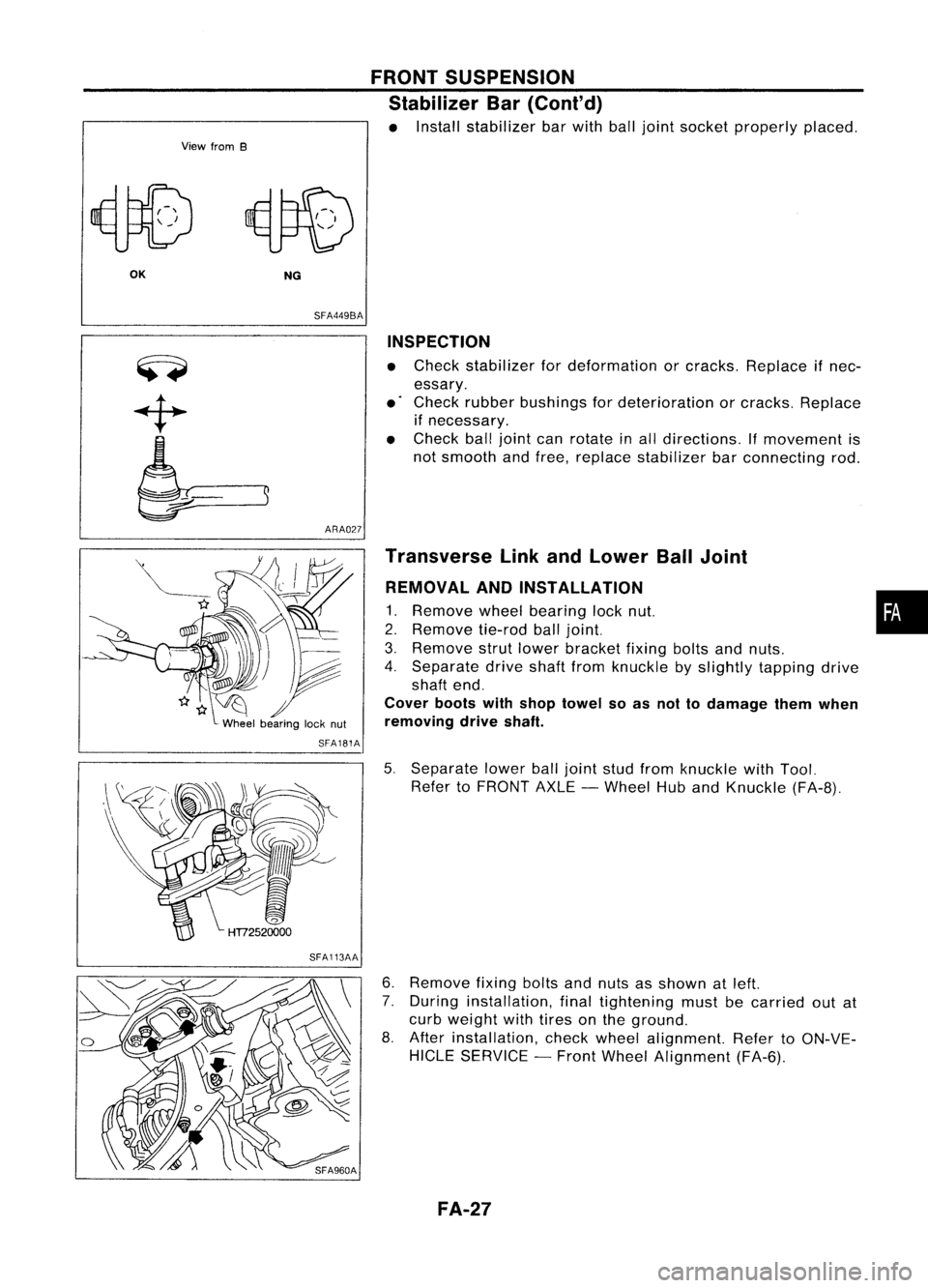
• Install stabilizer barwith balljoint socket properly placed.
OK NG
SFA449BA
ARA027 INSPECTION
• Check stabilizer fordeformation orcracks. Replace ifnec-
essary.
• Check rubber bushings fordeterioration orcracks. Replace
if necessary.
• Check balljoint canrotate inall directions. If
movement
is
not smooth andfree, replace stabilizer barconnecting rod.
SFA181A
SFA113AA Transverse
LinkandLower BallJoint
REMOVAL ANDINSTALLATION
1. Remove
wheelbearing locknut. •
2. Remove
tie-rodballjoint.
3. Remove
strutlower bracket fixingboltsandnuts.
4. Separate driveshaftfromknuckle byslightly tapping drive
shaft end.
Cover bootswithshop towel soas not todamage themwhen
removing driveshaft.
5. Separate lowerballjoint studfrom knuckle withTool.
Refer toFRONT AXLE-Wheel HubandKnuckle (FA-8).
6. Remove
fixingboltsandnuts asshown atleft.
7. During installation, finaltightening mustbecarried outat
curb weight withtires onthe ground.
8. After installation, checkwheel alignment. RefertoON-VE-
HICLE SERVICE -Front Wheel Alignment (FA-6).
FA-27
Page 710 of 1701
,...............A
SFA858AFRONT
SUSPENSION
Transverse LinkandLower BallJoint (Cont'd)
INSPECTION
• Check transverse linkfordamage, cracksordeformation.
Replace ifnecessary.
• Check rubber bushing fordamage, cracksanddeformation.
Replace transverse linkifnecessary.
• Check balljoint forexcessive play.Replace transverse link
assembly ifany ofthe following exists:
• Ball stud isworn .
• Joint ishard toswing .
• Play inaxial direction isexcessive.
Before checking, turnballjoint atleast 10revolutions so
that balljoint isproperly brokenin.
Swinging force
"A":
(measuring point:cotter pinhole ofball stud):
8.24 -57.37 N(0.84 -5.85 kg,1.85 -12.90 Ib)
Turning torque
"B":
0.49 -3.43 N'm(5.0-35 kg-em, 4.3-30.4 in-Ib)
Vertical endplay
"e":
o
mm (0in)
• Check dustcover fordamage. Replaceitand cover clamp
if necessary.
FA-28
Page 711 of 1701
SERVICEDATAANDSPECIFICATIONS (50S)
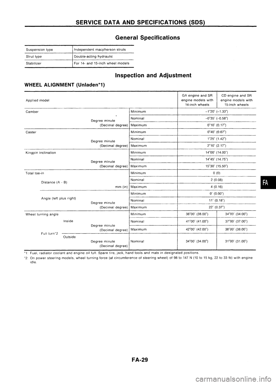
General Specifications
Suspension type
Strut type
Stabilizer Independent
macpherson struts
Double-acting hydraulic
For 14-and 15-inch wheelmodels
Inspection andAdjustment
WHEEL ALIGNMENT (Unladen*1)
GAengine andSR CDengine andSR
Applied model engine
models with enginemodels with
14-inch wheels 15-inchwheels
Camber Minimum
-no'
(-1.33')
.
Degree minute Nominal
-0'35'
(-0.58')
(Decimal degree)Maximum 0'10'
(0.1
r)
Caster Minimum
0'40'(0.6r)
Degree minute Nominal
1
'25' (1.42')
(Decimal degree)Maximum 2'10'
(217")
Kingpin inclination Minimum14'00'
(14.00')
Degree minute Nominal
14'45'
(14.75')
(Decimal degree)Maximum 15'30'
(15.50')
Total toe-in Minimum0(0)
Distance (A-B) Nominal
2(008)
mm (in) Maximum 4(0.16)
Minimum 0'
(0.00')
Angle (leftplus right)
Nominal 11'
(0.18')
Degree minute
(Decimal degree)Maximum 22'
(0.37")
Wheel turning angle Minimum
38'00'
(38.00') 34'00'(34.00')
Inside Nominal4nO'
(41.00')
3rOO'(37.00')
Degree minute
(Decimal degree)Maximum
42'00'
(42.00')
38'00'(38.00')
Full (urn'2
Outside
Degreeminute Nominal 34'00'
(34.00') 31'00'(3100')
(Decimal degree)
'1' Fuel, radiator coolantandengine oilfull. Spare tire,jack, hand tools andmats indesignated positions.
'2: On power steering models,wheelturning force(atcircumference ofsteering wheel)of98 to147 N(10 to15 kg, 22to33 Ib)with engine
idle
FA-29
•
Page 1491 of 1701
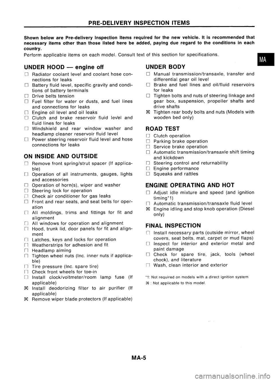
PRE-DELIVERYINSPECTIONITEMS
Shown belowarePre-delivery InspectionItemsrequired forthe new vehicle. Itis recommended that
necessary itemsotherthanthose listedherebeadded, payingdueregard tothe conditions ineach
country.
Perform applicable itemsoneach model. Consult textofthis section forspecifications .
UNDER HOOD-engine off
o
Radiator coolantlevelandcoolant hosecon-
nections forleaks
o
Battery fluidlevel, specific gravityandcondi-
tions ofbattery terminals
o
Drive beltstension
D
Fuel filter forwater ordusts, andfuel lines
and connections forleaks
[] Engine oillevel andoilleaks
D
Clutch andbrake reservoir fluidlevel and
fluid lines forleaks
o
Windshield andrear window washerand
headlamp cleanerreservoir fluidlevel
D
Power steering reservoir fluidlevel andhose
connections forleaks
ON INSIDE ANDOUTSIDE
D
Remove frontspring/strut spacer(Ifapplica-
ble)
D
Operation ofall instruments, gauges,lights
and accessories
o
Operation ofhorn(s), wiperandwasher
[] Steering lockforoperation
[] Check airconditioner forgas leaks
o
Front andrear seats, andseat belts foroper-
ation
n
All moldings, trimsandfittings forfitand
alignment
[J
Allwindows foroperation andalignment
n
Hood, trunklid,door panels forfitand align-
ment
[1
Latches, keysandlocks foroperation
rl
Weatherstrips foradhesion andfit
[l
Headlamp aiming
I~ Tighten wheelnuts(Inc. inner nutsifapplica-
ble)
IJ Tire pressure (Inc.spare tire)
Il
Check frontwheels fortoe-in
IJ Install clock/voltmeter/room lampfuse(If
applicable)
~ Install deodorizing filtertoair purifier (If
applicable)
~ Remove wiperbladeprotectors (Ifapplicable)
UNDER
BODY
o
Manual transmission/transaxle, transferand
differential gearoillevel
D
Brake andfuel lines andoil/fluid reservoirs
for leaks
D
Tighten boltsandnuts ofsteering linkageand
gear box,suspension, propellershaftsand
drive shafts
~ Tighten rearbody boltsandnuts (Models with
wooden bedonly)
ROAD TEST
D
Clutch operation
D
Parking brakeoperation
[J
Service brakeoperation
D
Automatic transmission/transaxle shifttiming
and kickdown
[] Steering controlandreturnability
o
Engine performance
D
Squeaks andrattles
ENGINE OPERATING ANDHOT
D
Adjust idlemixture andspeed (andignition
timing*1)
n
Automatic transmission/transaxle fluidlevel
~ Engine idlingandstop knob operation (Diesel
only)
FINAL INSPECTION
n
Install necessary parts(outside mirror,wheel
covers, seatbelts, mat,carpet ormud flaps)
[1
Inspect forinterior andexterior metaland
paint damage
[] Check forspare tire,jack, tools (wheel
chock), andliterature
n
Wash, cleaninterior andexterior
"1: Not required onmodels withadirect ignition system
~ :Not appiicable tothis model.
•
MA-5