Page 1613 of 1701
ON-VEHICLESERVICE
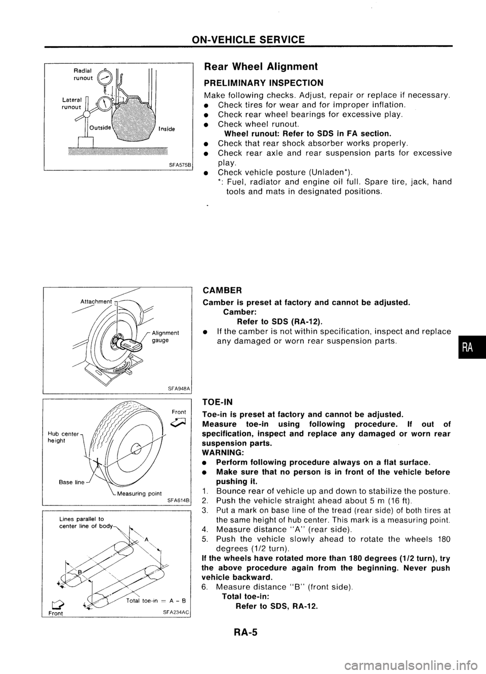
Rear Wheel Alignment
PRELIMINARY INSPECTION
Make following checks.Adjust,repairorreplace ifnecessary.
• Check tiresforwear andforimproper inflation.
• Check rearwheel bearings forexcessive play.
• Check wheelrunout.
Wheel runout: RefertoSOS inFA section.
• Check thatrear shock absorber worksproperly.
• Check rearaxleandrear suspension partsforexcessive
SFA575B
play.
• Check vehicle posture (Unladen*).
*: Fuel, radiator andengine oilfull. Spare tire,jack, hand
tools andmats indesignated positions.
•
CAMBER
Camber ispreset atfactory andcannot beadjusted.
Camber: Refer toSOS (RA-12).
• Ifthe camber isnot within specification, inspectandreplace
any damaged orworn rearsuspension parts.
TOE-IN
Toe-in ispreset atfactory andcannot beadjusted.
Measure toe-inusingfollowing procedure. Ifout of
specification, inspectandreplace anydamaged orworn rear
suspension parts.
WARNING:
• Perform following procedure alwaysonaflat surface.
• Make surethatnoperson isin front ofthe vehicle before
pushing it.
1. Bounce rearofvehicle upand down tostabilize theposture.
2. Push thevehicle straight aheadabout5m (16
ft).
3. Putamark onbase lineofthe tread (rearside) ofboth tires at
the same height ofhub center. Thismark isameasuring point.
4. Measure distance"A"(rear side).
5. Push thevehicle slowlyaheadtorotate thewheels 180
degrees (1/2turn).
If the wheels haverotated morethan180degrees (1/2turn), try
the above procedure againfromthebeginning. Neverpush
vehicle backward.
6. Measure distance"B"(front side).
Total toe-in:
Refer toSOS, RA-12.
Front
SFA948A
SFA614B
SFA234AC
Lines
parallel to
center lineofbOdY~
Q
Front
Hub
center
height
RA-5
Page 1616 of 1701
REARSUSPENSION
SEC. 431
~:N'm (kg-m. fl-Ib)
L'~
~;.;
~~.4,
18 •25)
~'
\ \ i---J
~~ ~
- ~98•118 (
I~ / 110-12,72-87) ~-~~~
@
~
"
\..-~
~ ~;:;:Y ~ '-~.
--...~~ ~~98-118
~ (10-12, 72•87)
~~A
98-118 (10-12, 72-87)
When
installing eachrubber part,finaltightening
must becarried outunder unladen condition"
with tires onground.
" Fuel, radiator coolantandengine allfull.
Spare tire,jack, handtools andmats In~
designated positions. ~
~~ 18.24(1.8.2.4, 13-17)~
~
~A
19•22 (1.9 -2.2, 14•16)~
~
~
~
:\\
\--/
Front
SRA694AA
(1)
Shock absorber cap
@
Washer
@
Bushing
@
Shock absorber mounting seal
@
Shock absorber mounting
bracket
@
Upper spring seatrubber
(J)
Bushing
@
Bound bumper cover
@
Bound bumper
@J
Coilspring
Q!J
Shock absorber
@
Torsion beam
@
Lateral link
Q4)
Control rod
@)
ABSsensor
RA-8
Page 1617 of 1701
SRA696A
SRA697A
S
Control rod
Lateral link
~H";""I"
ITorsion
beam
SRA698AREAR
SUSPENSION
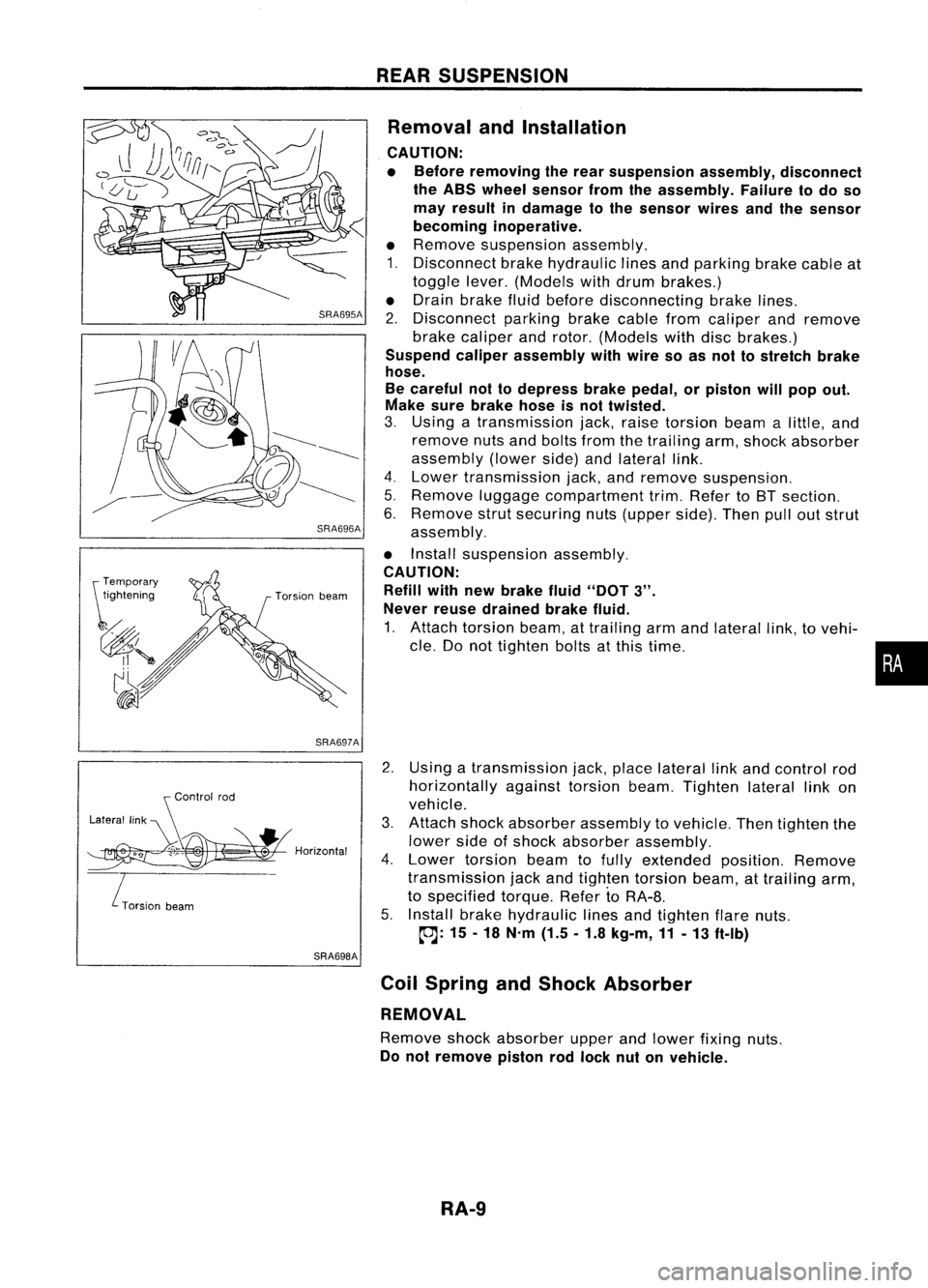
Removal andInstallation
CAUTION:
• Before removing therear suspension assembly,disconnect
the ABS wheel sensor fromtheassembly. Failuretodo so
may result indamage tothe sensor wiresandthesensor
becoming inoperative.
• Remove suspension assembly.
1. Disconnect brakehydraulic linesandparking brakecableat
toggle lever.(Models withdrum brakes.)
• Drain brake fluidbefore disconnecting brakelines.
2. Disconnect parkingbrakecablefromcaliper andremove
brake caliper androtor. (Models withdiscbrakes.)
Suspend caliperassembly withwire soasnot tostretch brake
hose.
Be careful nottodepress brakepedal, orpiston willpop out.
Make surebrake hoseisnot twisted.
3. Using atransmission jack,raise torsion beamalittle, and
remove nutsandbolts fromthetrailing arm,shock absorber
assembly (lowerside)andlateral link.
4. Lower transmission jack,andremove suspension.
5. Remove luggagecompartment trim.Refer toBT section.
6. Remove strutsecuring nuts(upper side).Thenpulloutstrut
assembly.
• Install suspension assembly.
CAUTION: Refill withnewbrake fluid"DOT
3".
Never reusedrained brakefluid.
1. Attach torsion beam,attrailing armandlateral link,tovehi-
cle. Donot tighten boltsatthis time.
2. Using atransmission jack,place lateral linkand control rod
horizontally againsttorsionbeam.Tighten laterallinkon
vehicle.
3. Attach shockabsorber assembly tovehicle. Thentighten the
lower sideofshock absorber assembly.
4. Lower torsion beamtofully extended position.Remove
transmission jackandtighten torsion beam,attrailing arm,
to specified torque.RefertoRA-8.
5. Install brakehydraulic linesandtighten flarenuts.
~: 15-18 N'm (1.5.1.8 kg-m,11-13 ft-Ib)
Coil Spring andShock Absorber
REMOVAL
Remove shockabsorber upperandlower fixing nuts.
Do not remove pistonrodlock nutonvehicle.
RA-9
•
Page 1618 of 1701
REARSUSPENSION
Coil Spring andShock Absorber (Conl'd)
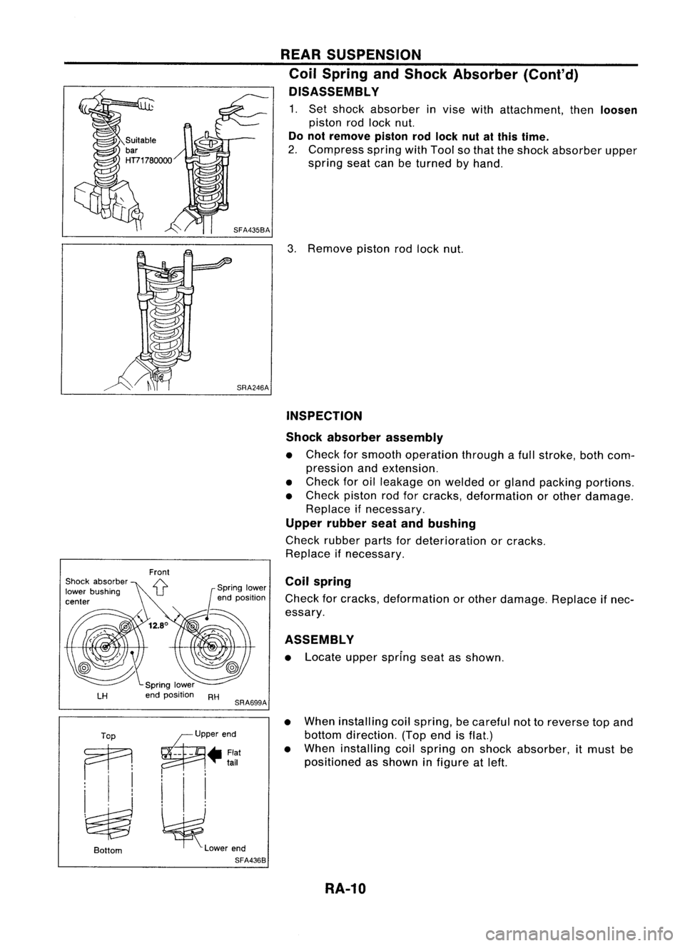
DISASSEMBL Y
1. Set shock absorber invise withattachment, then
loosen
piston rodlock nut.
Do not remove pistonrodlock nutatthis time.
2. Compress springwithTool sothat theshock absorber upper
spring seatcanbeturned byhand.
3. Remove pistonrodlock nut.
INSPECTION
Shock absorber assembly
• Check forsmooth operation throughafull stroke, bothcom-
pression andextension.
• Check foroilleakage onwelded orgland packing portions.
• Check pistonrodforcracks, deformation orother damage.
Replace ifnecessary.
Upper rubber seatandbushing
Check rubber partsfordeterioration orcracks.
Replace ifnecessary.
ASSEMBLY
• Locate upperspring seatasshown.
Coil
spring
Check forcracks, deformation orother damage. Replaceifnec-
essary.
LH
RH
SRA699A
•
Top ~P"'"d
Ai
--
- • Flat
•
tail
i 'I
~ ~l_""d
Bottom
SFA4368
When
installing coilspring, becareful nottoreverse topand
bottom direction. (Topendisflat.)
When installing coilspring onshock absorber, itmust be
positioned asshown infigure atleft.
RA-10
Page 1619 of 1701
REARSUSPENSION
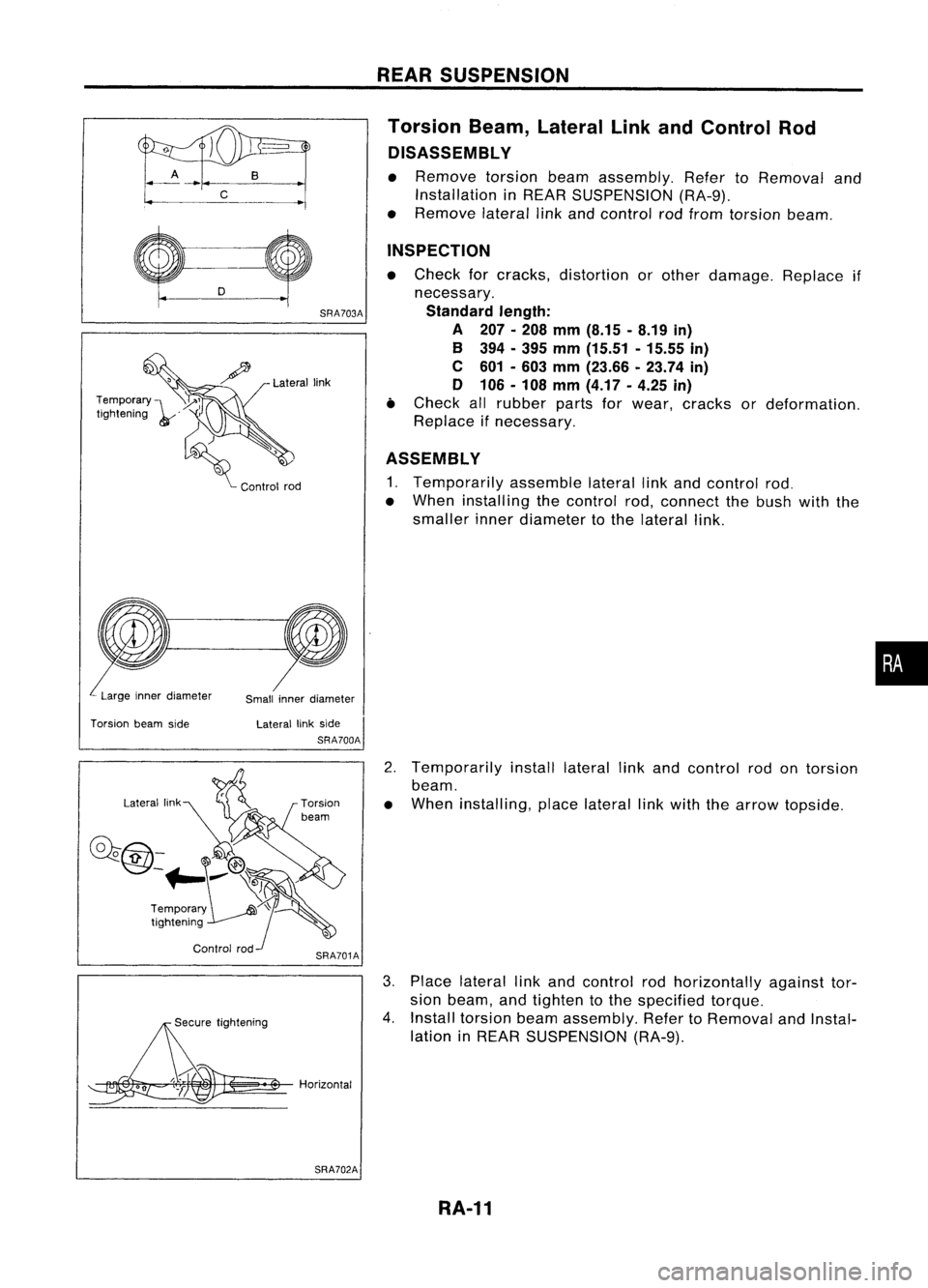
Torsion Beam,Lateral LinkandControl Rod
DISASSEMBL Y
• Remove torsionbeamassembly. RefertoRemoval and
Installation inREAR SUSPENSION (RA-9).
• Remove laterallinkand control rodfrom torsion beam.
Lateral link
SRA703A
INSPECTION
• Check forcracks, distortion orother damage. Replaceif
necessary.
Standard length:
A 207.208 mm(8.15 -8.19 in)
B 394 -395 mm (15.51 -15.55 in)
C 601 -603 mm (23.66 .23.74 in)
o 106 -108 mm (4.17 -4.25 in)
• Check allrubber partsforwear, cracks ordeformation.
Replace ifnecessary.
ASSEMBLY
1. Temporarily assemblelaterallinkand control rod.
• When installing thecontrol rod,connect thebush withthe
smaller innerdiameter tothe lateral link.
Temporary
I~~
Ilgh"oIog ,,'
d) ,
~ Cootrol100
Large innerdiameter
Smallinnerdiameter
•
Torsion beamside Laterallinkside
SRA700A
2.Temporarily installlateral linkand control rodontorsion
beam.
• When installing, placelateral linkwith thearrow topside.
0""
;;~h"0109
~ .$
Horizontal 3.
Place lateral linkand control rodhorizontally againsttor-
sion beam, andtighten tothe specified torque.
4. Install torsion beamassembly. RefertoRemoval andInstal-
lation inREAR SUSPENSION (RA-9).
SRA702A
RA-11
Page 1620 of 1701
SERVICEDATAANDSPECIFICATIONS (50S)
General Specifications
Suspension type
Shock absorber type
Stabilizer Multi-link
beamsuspension
Double-acting hydraulic
Standard equipment
WHEEL ALIGNMENT (Unladen*) Inspection
andAdjustment
WHEEL BEARING
Camber Minimum-1'45'
(-1.75')
Degree minute Nominal
-1'00'
(-1.00')
(Decimal degree) Maximum -0'15'
(-0.25')
Total toe-in Minimum-3
(-0.12)
Distance (A-B) Nominal
1
(0.04)
mm (in) Maximum 5(0.20)
Angle (leftpius right) Minimum -16'(-0.27')
Degree minute Nominal
5'
(0.08')
(Decimal degree)Maximum 26'
(0.43') Wheel
bearing axialendplay
mm (in)
Wheel bearing locknuttighten-
ing torque
N'm(kg-m. ft-lb) 0.05
(0.0020) orless
186 -255
(19 -26, 137 -188)
': Fuel, radiator coolantandengine oilfull. Spare tire.jack, hand
tools andmats indesignated positions.
RA-12
Page 1671 of 1701
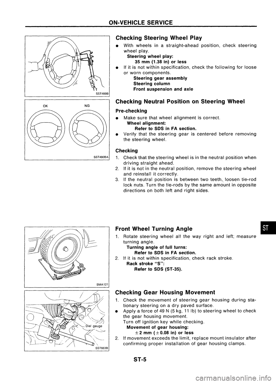
ON-VEHICLESERVICE
Checking SteeringWheelPlay
• With wheels inastraight-ahead position,checksteering
wheel play.
Steering wheelplay:
35 mm (1.38 in)orless
• Ifit is not within specification, checkthefollowing forloose
or worn components.
Steering gearassembly
Steering column
Front suspension andaxle
SST489B
OK
NGChecking
NeutralPosition onSteering Wheel
Pre-checking
• Make surethatwheel alignment iscorrect.
Wheel alignment:
Refer toSOS inFA section.
• Verify thatthesteering geariscentered beforeremoving
the steering wheel.
Checking
SST490BA
1.Check thatthesteering wheelisin the neutral position when
driving straight ahead.
2. Ifit is not inthe neutral position, removethesteering wheel
and reinstall itcorrectly.
3. Ifthe neutral position isbetween twoteeth,. loosen tie-rod
lock nuts. Turnthetie-rods bythe same amount inopposite
directions onboth leftand right sides.
Front Wheel Turning Angle •
1. Rotate steering wheelallthe way right andleft;measure
turning angle.
Turning angleoffull turns:
Refer toSOS inFA section.
2. Ifit is not within specification, checkrackstroke.
Rack stroke
"S":
Refer toSOS (ST-35).
SMA127 Checking GearHousing Movement
1. Check themovement ofsteering gearhousing duringsta-
tionary steering onadry paved surface.
• Apply aforce of49 N(5 kg, 11Ib) tosteering wheeltocheck
the gear housing movement.
Turn offignition keywhile checking.
Movement ofgear housing:
:I:
2 mm
(:I:
0.08 in)orless
2. Ifmovement exceedsthelimit, replace mountinsulator after
confirming properinstallation ofgear housing clamps.
ST-5