1995 NISSAN ALMERA N15 run flat
[x] Cancel search: run flatPage 1350 of 1701

COMPRESSION PRESSURE Inspection
andAdjustment
VALVE
Standard
Limit
Difference limit
between cylinders
CYLINDER HEAD
Head surface flatness
Standard Limit
Nominal")
SERVICEDATAANDSPECIFICATIONS (SDS)
COMPRESSION PRESSURE Inspection
andAdjustment
VALVE
Standard
Limit
Difference limit
between cylinders
CYLINDER HEAD
Head surface flatness
Standard Limit
Nominal cylinderhead
height Unit:
kPa(bar, kg/cm
2,
psi)at
200
rpm
3,138 (31.4, 32,455)
2,452 (24.5, 25,356)
490 (4.9, 5,71)
Unit: mm(in)
Less than
0.05(0.0020)
0.1 (0,004)
137.9 -138.1
(5.429 -5.437)
T
(Margin thickness)
1t
f"~ if
Valve headdiameter "D"
Intake
Exhaust
Valve length "L" Unit:
mm(in)
SEM188
39.0 -39.3 (1.535 -1.547)
32.0 -32.2 (1,260 -1.268)
•
CAMSHAFT ANDCAMSHAFT BEARING
Camshaft journal
clearance
Inner diameter of
camshaft bearing
Outer diameter of
camshaft journal
Camshaft runout
Camshaft endplay Standard
0.045 -0.086
(0.0018 -0.0034)
30.000 -30.021
(1.1811 -1.1819)
29.935 -29.955
(1.1785 -11793)
Less than
0.02 (0.0008)
0.115 -0.188
(0.0045 -0.0074)
Unit:
mm(in)
Max. tolerance
0.1 (0.004)
0.05 (0.0020)
EM671
Intake
Exhaust
Valve stemdiameter "d"
Intake
Exhaust
Valve seatangle "u"
Valve margin
"r
limit
Valve stemendsurface grinding
limit
100.53
-100.97
(3.9579 -3.9752)
100.38 -100.82
(3.9520 -3.9693)
6.965 -6.980
(0.2742 -0.2748)
6.945 -6.960
(0.2734 -0.2740)
45°30'
0.5 (0.020)
0.5 (0.020)
Cam height "A"
Intake
Exhaust
49.20
-49.25 (1.9370 -1.9390)
49.15 -49.20 (1.9350 -1.9370)
EM-171
Page 1356 of 1701
PRECAUTIONS
Observe thefollowing precautions toensure safeandproper
servicing.
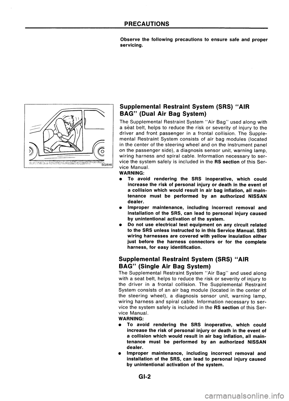
Supplemental RestraintSystem(SRS)"AIR
BAG" (DualAirBag System)
The Supplemental RestraintSystem"AirBag" usedalong with
a seat belt,helps toreduce therisk orseverity ofinjury tothe
driver andfront passenger inafrontal collision. TheSupple-
mental Restraint Systemconsists ofair bag modules (located
in the center ofthe steering wheelandonthe instrument panel
on the passenger side),adiagnosis sensorunit,warning lamp,
wiring harness andspiral cable. Information necessarytoser-
vice thesystem safelyisincluded inthe RSsection ofthis Ser-
vice Manual.
WARNING:
• To avoid rendering theSRS inoperative, whichcould
increase therisk ofpersonal injuryordeath inthe event of
a collision whichwould resultinair bag inflation, allmain-
tenance mustbeperformed byan authorized NISSAN
dealer.
• Improper maintenance, includingincorrectremovaland
installation ofthe SRS, canlead topersonal injurycaused
by unintentional activationofthe system.
• Donot use electrical testequipment onany circuit related
to the SRS unless instructed tointhis Service Manual. SRS
wiring harnesses arecovered withyellow insulation either
just before theharness connectors orfor the complete
harness, foreasy identification.
Supplemental RestraintSystem(SRS)"AIR
BAG" (Single AirBag System)
The Supplemental RestraintSystem"AirBag" andused along
with aseat belt, helps toreduce therisk orseverity ofinjury to
the driver inafrontal collision. TheSupplemental Restraint
System consists ofan air bag module (located inthe center of
the steering wheel),adiagnosis sensorunit,warning lamp,
wiring harness andspiral cable. Information necessarytoser-
vice thesystem safelyisincluded inthe RSsection ofthis Ser-
vice Manual.
WARNING:
• To avoid rendering theSRS inoperative, whichcould
increase therisk ofpersonal injuryordeath inthe event of
a collision whichwould resultinair bag inflation, allmain-
tenance mustbeperformed byan authorized NISSAN
dealer.
• Improper maintenance, includingincorrectremovaland
installation ofthe SRS, canlead topersonal injurycaused
by unintentional activationofthe system.
GI-2
Page 1404 of 1701
\"AIR
BAG\" (DualAirBag System)
The Supplemental RestraintSystem\"AirBag\" usedalong withaseat belt,helps toreduce therisk or
se")
PRECAUTIONSANDPREPARATION
Supplemental RestraintSystem(SRS)"AIR
BAG" (DualAirBag System)
The Supplemental RestraintSystem"AirBag" usedalong withaseat belt,helps toreduce therisk or
severity ofinjury tothe driver andfront passenger inafrontal collision. TheSupplemental Restraint
System consists ofair bag modules (locatedinthe center ofthe steering wheelandonthe instrument
panel onthe passenger side),adiagnosis sensorunit,warning lamp,wiring harness andspiral cable.
Information necessarytoservice thesystem safelyisincluded inthe
RSsection
ofthis Service Manual.
WARNING:
• Toavoid rendering theSRS inoperative, whichcouldincrease therisk ofpersonal injuryordeath
in the event ofacollision whichwould resultinair bag inflation, allmaintenance mustbeperformed
by an authorized NISSANdealer.
• Improper maintenance, includingincorrectremovalandinstallation ofthe SRS, canlead topersonal
injury caused byunintentional activationofthe system.
• Donot use electrical testequipment onany circuit related tothe SRS unless instructed tointhis
Service Manual. SRSwiring harnesses arecovered withyellow insulation eitherjustbefore the
harness connectors orfor the complete harness,foreasy identification.
Supplemental RestraintSystem(SRS)"AIR
BAG" (Single AirBag System)
The Supplemental RestraintSystem"AirBag" andused along withaseat belt,helps toreduce therisk
or severity ofinjury tothe driver inafrontal collision. TheSupplemental RestraintSystemconsists of
an air bag module (located inthe center ofthe steering wheel),adiagnosis sensorunit,warning lamp,
wiring harness andspiral cable. Information necessarytoservice thesystem safelyisincluded inthe
RS section
ofthis Service Manual.
WARNING: • Toavoid rendering theSRS inoperative, whichcouldincrease therisk ofpersonal injuryordeath
in the event ofacollision whichwould resultinair bag inflation, allmaintenance mustbeperformed
by anauthorized NISSANdealer.
• Improper maintenance, includingincorrectremovalandinstallation ofthe SRS, canlead topersonal
injury caused byunintentional activationofthe system.
• Donot use electrical testequipment onany circuit related tothe SRS unless instructed tointhis
Service Manual.
HA-2
Page 1489 of 1701
\"AIR
BAG\" (DualAirBag System)
The Supplemental RestraintSystem\"AirBag\", usedalong withaseat belt,helps toreduce therisk or�")
PRECAUTIONSANDPREPARATION
Supplemental RestraintSystem(SRS)"AIR
BAG" (DualAirBag System)
The Supplemental RestraintSystem"AirBag", usedalong withaseat belt,helps toreduce therisk or•
severity ofinjury tothe driver andfront passenger inafrontal collision. TheSupplemental Restraint
i
System consists ofair bag modules (locatedinthe center ofthe steering wheelandonthe instrument
panel onthe passenger side).adiagnosis sensorunit,warning lamp,wiring harness andspiral cable.
Information necessarytoservice thesystem safelyisincluded inthe
RSsection
ofthis Service Manual.
WARNING:
• Toavoid rendering theSRS inoperative, whichcouldincrease therisk ofpersonal injuryordeath
in the event ofacollision whichwould resultinair bag inflation, allmaintenance mustbeperformed
by an authorized NISSANdealer.
• Improper maintenance, includingincorrectremovalandinstallation ofthe SRS, canlead topersonal
injury caused byunintentional activationofthe system.
• Donot use electrical testequipment onany circuit related tothe SRS unless instructed tointhis
Service Manual. SRSwiring harnesses arecovered withyellow insulation eitherjustbefore the
harness connectors orfor the complete harness,foreasy identification.
Supplemental RestraintSystem(SRS)"AIR
BAG" (Single AirBag System)
The Supplemental RestraintSystem"AirBag", usedalong withaseat belt,helps toreduce therisk or
severity ofinjury tothe driver inafrontal collision. TheSupplemental RestraintSystemconsists ofan
air bag module (located inthe center ofthe steering wheel),adiagnosis sensorunit,warning lamp,
wiring harness andspiral cable. Information necessarytoservice thesystem safelyisincluded inthe
RS section
ofthis Service Manual.
WARNING:
• Toavoid rendering theSRS inoperative, whichcouldincrease therisk ofpersonal injuryordeath
in the event ofacollision whichwould resultinair bag inflation, allmaintenance mustbeperformed
by an authorized NISSANdealer.
• Improper maintenance, includingincorrectremovalandinstallation ofthe SRS, canlead topersonal
injury caused byunintentional activationofthe system.
• Donot use electrical testequipment onany circuit related tothe SRS.
MA-3
Page 1613 of 1701

ON-VEHICLESERVICE
Rear Wheel Alignment
PRELIMINARY INSPECTION
Make following checks.Adjust,repairorreplace ifnecessary.
• Check tiresforwear andforimproper inflation.
• Check rearwheel bearings forexcessive play.
• Check wheelrunout.
Wheel runout: RefertoSOS inFA section.
• Check thatrear shock absorber worksproperly.
• Check rearaxleandrear suspension partsforexcessive
SFA575B
play.
• Check vehicle posture (Unladen*).
*: Fuel, radiator andengine oilfull. Spare tire,jack, hand
tools andmats indesignated positions.
•
CAMBER
Camber ispreset atfactory andcannot beadjusted.
Camber: Refer toSOS (RA-12).
• Ifthe camber isnot within specification, inspectandreplace
any damaged orworn rearsuspension parts.
TOE-IN
Toe-in ispreset atfactory andcannot beadjusted.
Measure toe-inusingfollowing procedure. Ifout of
specification, inspectandreplace anydamaged orworn rear
suspension parts.
WARNING:
• Perform following procedure alwaysonaflat surface.
• Make surethatnoperson isin front ofthe vehicle before
pushing it.
1. Bounce rearofvehicle upand down tostabilize theposture.
2. Push thevehicle straight aheadabout5m (16
ft).
3. Putamark onbase lineofthe tread (rearside) ofboth tires at
the same height ofhub center. Thismark isameasuring point.
4. Measure distance"A"(rear side).
5. Push thevehicle slowlyaheadtorotate thewheels 180
degrees (1/2turn).
If the wheels haverotated morethan180degrees (1/2turn), try
the above procedure againfromthebeginning. Neverpush
vehicle backward.
6. Measure distance"B"(front side).
Total toe-in:
Refer toSOS, RA-12.
Front
SFA948A
SFA614B
SFA234AC
Lines
parallel to
center lineofbOdY~
Q
Front
Hub
center
height
RA-5
Page 1622 of 1701
\"AIR
BAG\" (DualAirBag System)
The Supplemental RestraintSystem\"AirBag\", usedalong withaseat belt, helps toreduce therisk or
severity ofinju")
PRECAUTION
Supplemental RestraintSystem(SRS)"AIR
BAG" (DualAirBag System)
The Supplemental RestraintSystem"AirBag", usedalong withaseat belt, helps toreduce therisk or
severity ofinjury tothe driver andfront passenger inafrontal collision. TheSupplemental Restraint
System consists ofair bag modules (locatedinthe center ofthe steering wheelandonthe instrument
panel onthe passenger side),adiagnosis sensorunit,warning lamp,wiring harness andspiral cable.
WARNING:
• Toavoid rendering theSRS inoperative, whichcouldincrease therisk ofpersonal injuryordeath
in the event ofacollision whichwould resultinair bag inflation, allmaintenance mustbeperformed
by an authorized NISSANdealer.
• Improper maintenance, includingincorrectremovalandinstallation ofthe SRS, canlead topersonal
injury caused byunintentional activationofthe system.
• Donot use electrical testequipment onany circuit related tothe SRS unless instructed tointhis
Service Manual. SRSwiring harnesses arecovered withyellow insulation eitherjustbefore the
harness connectors orfor the complete harness,foreasy identification.
Supplemental RestraintSystem(SRS)"AIR
BAG" (Single AirBag System)
The Supplemental RestraintSystem"AirBag", usedalong withaseat belt, helps toreduce therisk or
severity ofinjury tothe driver inafrontal collision. TheSupplemental RestraintSystemconsists ofan
air bag module (located inthe center ofthe steering wheel),adiagnosis sensorunit,warning lamp,
wiring harness andspiral cable.
WARNING:
• Toavoid rendering theSRS inoperative, whichcouldincrease therisk ofpersonal injuryordeath
in the event ofacollision whichwould resultinair bag inflation, allmaintenance mustbeperformed
by an authorized NISSANdealer.
• Improper maintenance, includingincorrectremovalandinstallation ofthe SRS, canlead topersonal
injury caused byunintentional activationofthe system.
• Donot use electrical testequipment onany circuit related tothe SRS unless instructed tointhis
Service Manual.
RS-2
Page 1628 of 1701

Precautions forSRS \"AirBag\" and\"Seat Belt
Pre-tensioner\" Service
• Donot use acircuit testertocheck SRScircuits.
• Before servicing theSRS. turnig")
SUPPLEMENTALRESTRAINTSYSTEM(SRS)
Precautions forSRS "AirBag" and"Seat Belt
Pre-tensioner" Service
• Donot use acircuit testertocheck SRScircuits.
• Before servicing theSRS. turnignition switch"OFF", disconnect bothbattery cablesandwait forat
least 10minutes.
For approximately 10minutes afterthecables areremoved, itis still possible forthe airbag to
deploy. Therefore, donot work onany SRS connectors orwires untilatleast 10minutes havepassed.
• For single airbag system, donot separate diagnosis sensorunitfrom steering wheel.
• For dual airbag system. diagnosis sensorunitmust always beinstalled withtheir arrow marks
"Q"
pointing towards thefront ofthe vehicle forproper operation. Alsocheck diagnosis sensorunitfor
cracks. deformities orrust before installation andreplace asrequired.
• The spiral cablemustbealigned withtheneutral position sinceitsrotations arelimited. Donot
attempt toturn steering wheelorcolumn afterremoval ofsteering gear.
• Handle airbag module carefully. Alwaysplaceitwith thepad side facing upward.
• Donot use oldbolts afterremoving anySRS parts; replace withnewones. Conduct self-diagnosis
to check entire SRSforproper function.
• For dual airbag system, instrument panelassembly shouldbereplaced afterairbag inflates.
X
X
Use
forspecial bolts
[TAMPER RESISTANT
TORX (SizeT50))
a:
3.5 (0.138)
dia.
b: 8.5 -8.6
(0.335 •0.339) dia.
c: approx.
10
(0.39) sq.
c
NT354
a
HT61961000
and
HT62152000 com-
bined *1 Special torxbit
Special
Service Tools
Application
Tool number
Description Seat
belt DualAir Single
Tool name
pre-ten-BagAirBag
sioner*2 Sstem Sstem
KV991072So Disposingofair bag
Air bag deployment kit module
KV991 06400
X
X
Deployment tool
KV991065So
Deployment tool
adapters
X
For passenger
air bag module
NT353
KV991 05300 Anchorthepassenger
Passenger airbag
airbag module
bracket
X
NT361
Unit:
mm(in)
*1: Special toolorcommercial equivalent
*2: Tools arenotapplicable becauseofits mechanical type.
RS-8
Page 1660 of 1701

COLLISIONDIAGNOSIS -Dual AirBag System
To repair theSRS, perform thefollowing steps.
When SRSisactivated inacollision:
CD
Replace thediagnosis sensorunit.
@ Remove
theairbag modules.
@
Check theSRS components usingthetable shown below:
• Replace anySRS components showing
visible
signsofdamage (dents,cracks, deformation).
@
Conduct self-diagnosis. Referto"Self-diagnosis" fordetails (RS-32). Ensuretheremainder ofthe
SRS isoperating properly.
@
Conduct self-diagnosis again.
When SRSisnot activated inacollision:
CD
Check theSRS components usingthetable shown below:
• Replace anySRS components showingvisiblesignsofdamage (dents,cracks, deformation).
@
Conduct self-diagnosis usingCONSULT and"'AIR BAG" warning lamp.Referto"Self-diagnosis" for
details (RS-32). EnsureentireSRSoperates properly.
SRS inspection
Part SRSisactivated
SRSisNOT activated
Air bag module REPLACE
1.Remove airbag module. Checkharness coverandconnectors fordamage,
(driver andpassen-
Installwithnew terminalsfordeformities, andharness forbinding.
ger side) bolts.
2-1.Install driverairbag module intothesteering wheeltocheck fitand align-
ment withthewheel.
2-2. Install passenger airbag module intotheinstrument paneltocheck fit
with theinstrument panel.
3. No damage found,reinstall withnewbolts.
4. Ifdamaged-REPLACE. Airbag must bedeployed beforediscarding.
Instrument panel
REPLACE 1.Check instrument panelforbending, deformities, orcracks.
Install withnew
2.Ifno damage isfound, reinstall withnewbolts.
bolts. 3.Ifdamaged-REPLACE.
Diagnosis sensor REPLACE
1.Check caseandbracket fordents, cracks ordeformities.
unit Installwithnew
2.Check connectors fordamage, andterminals fordeformities.
bolts. 3.Ifno damage isfound, reinstall withnewbolts.
4. Ifdamaged-REPLACE.
Steering wheel
1.Visually checksteering wheelfordeformities.
2. Check harness (builtintosteering wheel)andconnectors fordamage, andterminals fordeformi-
ties.
3. Install airbag module tocheck fitor alignment withsteering wheel.
4. Check steering wheelforexcessive freeplay.
5. Ifno damage isfound, reinstall withnewbolts.
6. Ifdamaged-REPLACE.
Spiral cable
1.Visually checklock(engagement) pinsandcombination switchfordamage.
2. Check connectors, flatcable andprotective tapefordamage.
3. Check steering wheelfornoise, binding orheavy operation.
4. Ifno damage isfound, reinstall withnew bolts.
5. Ifdamaged-REPLACE.
Harness andCon-
1.Check connectors forpoor connection, damage,andterminals fordeformities.
nectors 2.Check harness forbinding, chafing,cuts,ordeformities.
3. Ifno damage isfound, reinstall theharness andconnectors.
4. Damaged-REPLACE damagedsectionofharness. Donot attempt torepair, spliceormodify any
SRS harness.
RS-40