1995 NISSAN ALMERA N15 fuel cap
[x] Cancel search: fuel capPage 957 of 1701
EVAPORATIVEEMISSIONSYSTEM
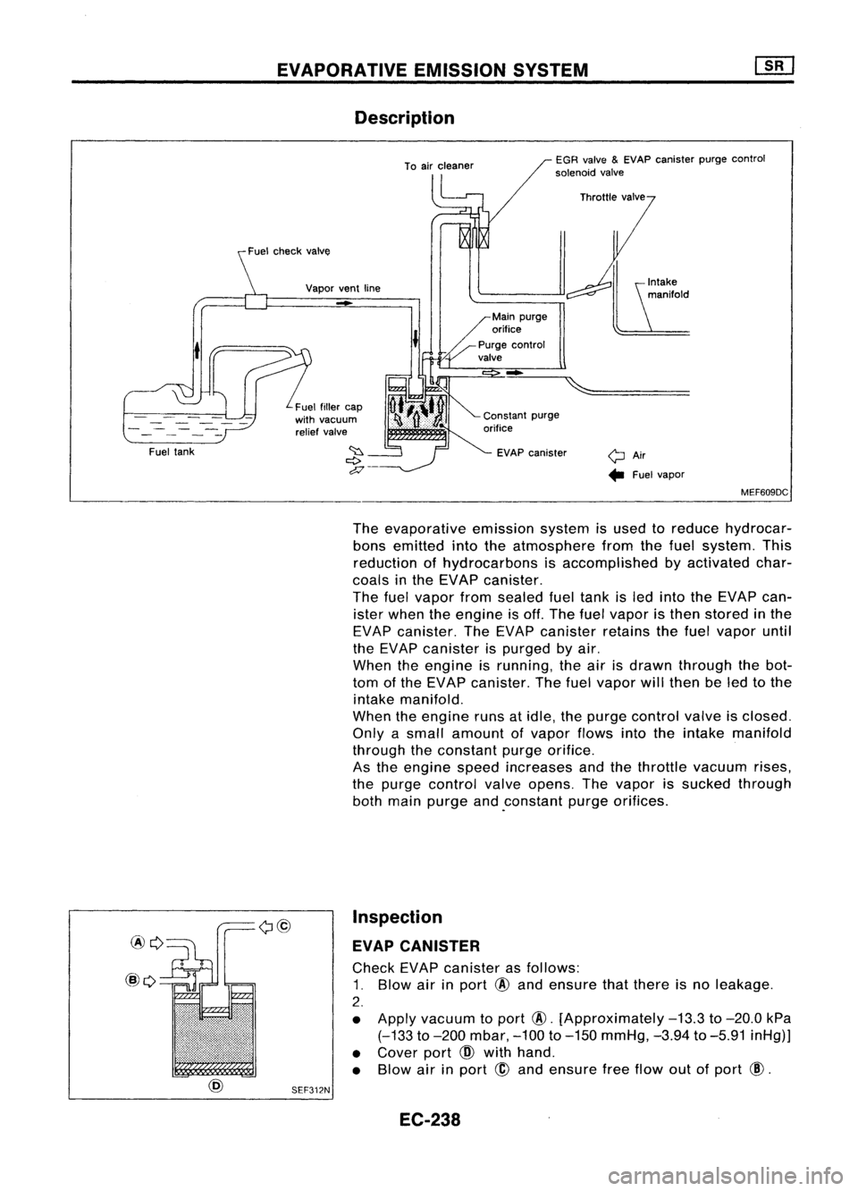
Description
yAir.. Fuelvapor
EGR
valve
&
EVAP canister purgecontrol
solenoid valve
-
EVAP canister
Vapor
ventline
-
Fuel fillercap
with vacuum
relief valve
t
Fuel tank
MEF609DC
The evaporative emissionsystemisused toreduce hydrocar-
bons emitted intotheatmosphere fromthefuel system. This
reduction ofhydrocarbons isaccomplished byactivated char-
coals inthe EVAP canister.
The fuelvapor fromsealed fueltank isled into theEVAP can-
ister when theengine isoff. The fuelvapor isthen stored inthe
EVAP canister. TheEVAP canister retainsthefuel vapor until
the EVAP canister ispurged byair.
When theengine isrunning, theairisdrawn through thebot-
tom ofthe EVAP canister. Thefuelvapor willthen beled tothe
intake manifold.
When theengine runsatidle, thepurge control valveisclosed.
Only asmall amount ofvapor flowsintotheintake manifold
through theconstant purgeorifice.
As the engine speedincreases andthethrottle vacuum rises,
the purge control valveopens. Thevapor issucked through
both main purge and.constant purgeorifices.
Inspection
EVAP CANISTER
Check EVAPcanister asfollows:
1. Blow airinport
@
and ensure thatthere isno leakage.
2.
• Apply vacuum toport
@.
[Approximately
-13.3
to
-20.0
kPa
(-133
to
-200
mbar,
-100
to
-150
mmHg,
-3.94
to
-5.91
inHg)]
• Cover port
CID
with hand.
• Blow airinport
@
and ensure freeflow outofport
@.
SEF312N
EC-238
Page 958 of 1701
EVAPORATIVEEMISSIONSYSTEM
Inspection (Conl'd)
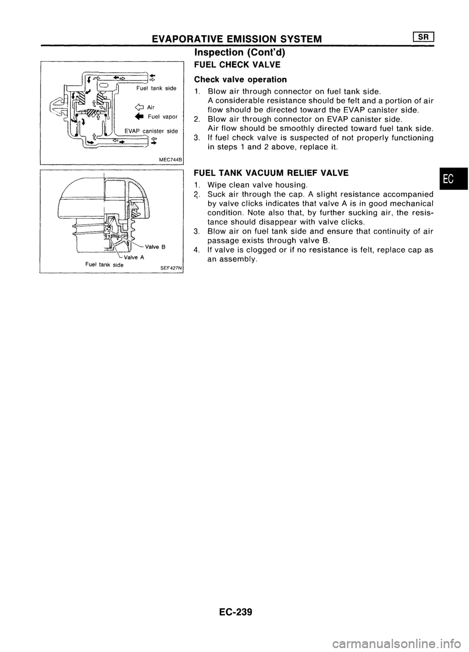
FUEL CHECK VALVE
Fuel tank side
+
0:>
Fuel lankside
QAir
.. Fuel vapor
EVAP canister side
..
MEC744B
SEF427N Check
valveoperation
1. Blow airthrough connector onfuel tank side.
A considerable resistanceshouldbefelt and aportion ofair
flow should bedirected towardtheEVAP canister side.
2. Blow airthrough connector onEVAP canister side.
Air flow should besmoothly directedtowardfueltank side.
3. Iffuel check valveissuspected ofnot properly functioning
in steps 1and 2above, replace it.
FUEL TANK VACUUM RELIEFVALVE
1. Wipe clean valvehousing.
4.
Suck airthrough thecap. Aslight resistance accompanied
by valve clicks indicates thatvalve Ais ingood mechanical
condition. Notealsothat, byfurther sucking air,the resis-
tance should disappear withvalve clicks.
3. Blow aironfuel tank sideandensure thatcontinuity ofair
passage existsthrough valveB.
4. Ifvalve isclogged orifno resistance isfelt, replace capas
an assembly.
EC-239
•
Page 961 of 1701
BASICSERVICE PROCEDURE
SEF310R
Vacuum
Fuelpressure
.... L
To
pressure regulator
SEF718B
'nsu'a,or~7
a-ring~1 ~
~> ~
InsUlalor~7
OJ'
Om~riJ$ _.
~lnjeCIOr
kJ
Insulator
11+-
1
~'I"
Localeplate
•. onthis side.
a-ring .
I
FuellUbe~i '.
assembly ,.
~'nsulator
I
SEF616N
MEC710B Fuel
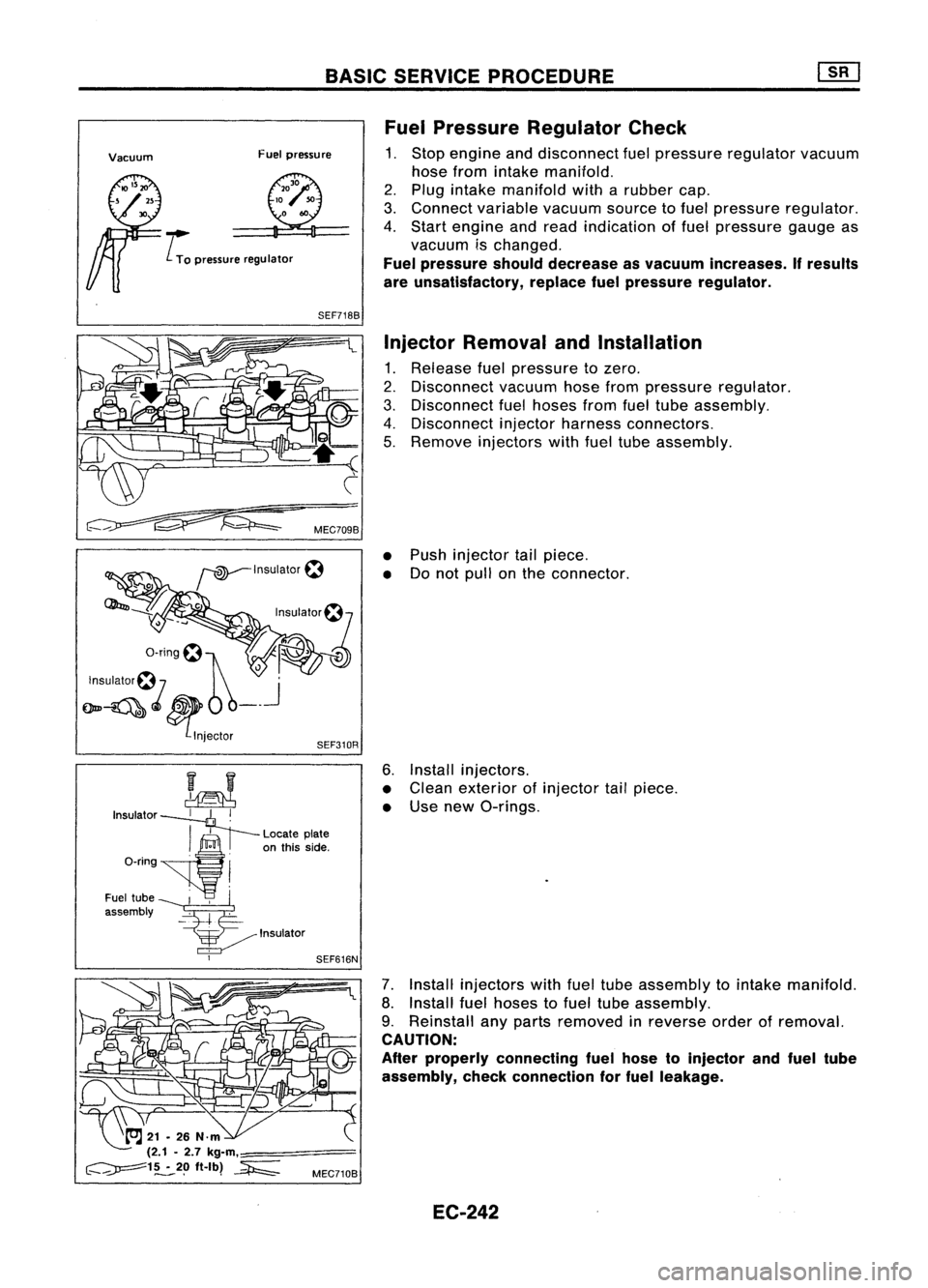
Pressure Regulator Check
1. Stop engine anddisconnect fuelpressure regulator vacuum
hose from intake manifold.
2. Plug intake manifold witharubber cap.
3. Connect variable vacuumsourcetofuel pressure regulator.
4. Start engine andread indication offuel pressure gaugeas
vacuum ischanged.
Fuel pressure shoulddecrease asvacuum increases. Ifresults
are unsatisfactory, replacefuelpressure regulator.
Injector Removal andInstallation
1. Release fuelpressure tozero.
2. Disconnect vacuumhosefrompressure regulator.
3. Disconnect fuelhoses fromfueltube assembly.
4. Disconnect injectorharness connectors.
5. Remove injectors withfueltube assembly.
• Push injector tailpiece.
• Donot pull onthe connector.
6. Install injectors.
• Clean exterior ofinjector tailpiece.
• Use new O-rings.
7. Install injectors withfueltube assembly tointake manifold.
8. Install fuelhoses tofuel tube assembly.
9. Reinstall anyparts removed inreverse orderofremoval.
CAUTION:
After properly connecting fuelhose toinjector andfuel tube
assembly, checkconnection forfuel leakage.
EC-242
Page 962 of 1701

BASICSERVICE PROCEDURE
Idle Speedllgnition TiminglldleMixtureRatio
Adjustment
PREPARATION
• Make surethatthefollowing partsarein
good order.
(1) Battery
(2) Ignition system
(3) Engine oiland coolant levels
(4) Fuses
(5) ECM harness connector
(6) Vacuum hoses
(7) Airintake system
(Oil filler cap,oillevel gauge, etc.)
(8) Fuel pressure
(9) Engine compression
(10) Throttle valve
Overall inspection sequence
INSPECTION
•
•
•
•
•
•
On
models equipped withairconditioner,
checks shouldbecarried outwhile theair
conditioner is"OFF".
On models equipped withautomatic
transaxle, whenchecking idlespeed, ignition
timing andmixture ratio,checks shouldbe
carried outwhile shiftlever isin "N" position.
When measuring "CO"percentage, insert
probe morethan40cm (15.7 in)into tailpipe.
Turn offheadlamps, heaterblower, rear
defogger. Keep frontwheels pointed straight ahead.
Make thecheck afterthecooling fanhas
stopped.
•
Perform diagnostic testmode II
(Self-diagnostic results).
OK
Check
&
adjust ignition timing.
Check
&
adjust idlespeed.
Check heated oxygen sensor
function. NG
Repair orreplace.
NG Check heated oxygen sensor
harness. NG
Repair orreplace harness.
OK OK
Check CO%. OKReplace heatedoxygen sensor.
NG
INSPECTION END Check
emission controlparts
and repair orreplace ifneces-
sary.
EC-243
NG
Check heated oxygen sensor
function.
OK
Page 995 of 1701
TROUBLEDIAGNOSIS -General Descrip_tio_n
1s_R_1
Symptom MatrixChart(Cont'd)
SYMPTOM
z
0
i=
«
W
a:
z
w
w
w
CJ
CJ
....J
....J
0
Z
a:
w
i=
0
a:
(.)
9
8
«
0.. i=
:I:
::J
(.)
z
:2
i='
en
«
:I:
8
:J
0..
(.)
Q
0
f:::.
CJ
:J
:2
a:
a:
:E
z
w
en
SYSTEM
....J
~
0
0
en
z
:J
w
Reference
0
0..
W
a
w
en
Cl
- Engine mechanical
&
other
I-
en
0
z
0
z
z
S:?-
a: 0..
....J
e-
(.)
0
page
I-
«
l-
ii.
9
~
....J
(.)
2-
a:
~
«
w
0
z
w
CJ
Cl
....J ....J
:.:::
0
:J
....J
Z
«
....J
u.
~
I-
(.)
u..
0
a
«
I-
w
«
Z
0
z
enen
w
en
a:
....J
I-
0..
Z
0
WW
:J
W
W
I-
....J
a:
Cl
0 0
9
en
0
a:
z
a:a:
a:
> >
«
0
«
>-
i=
u..
:J
:.:::
ii:
enen
0
:I:
Z Z
W
0
l-
ii:
w w
a:
Ci Ci
:I:
Z
«
w
:.:::
a:
z
en
en
:I:
(.)
(.)
w
CJ
a
I-
:.:::
a:a:
:.:::
w
a
w
w
a:
a:a:
~
a:
a:
:J
en
(.)
«
(.)
I-
(.)
(.)
w
w
w
« «
0
z
w
«
0
0..
«
u..
Z
x x
>>>
«
:I: :I:
a:
w
:I:
....J
Z
en
(l)
«
w w
w
00 0
(l)
1A 1B
1C 1F1H
1R 1S
1M 1J1L1K
1T
1V
1N
1P1X 1Y
Fuel Fueltank
00 0
Fuel piping
00 0000 000
0
Vapor lock
00
Valve deposit
000 000 00 0
Poor fuel(Heavy weightgasoline. Low
0000 00 00
0
-
octane)
Air Airduct
00 00 0
Air cleaner
0
0
00 0
Air leakage fromairduct
00 00 00 0
0 0
0
(Mass airflow sensor -throttle body)
Throttle body.Throttle wire
•
•
•
•
• •
•
FE
section
Air leakage fromintake
manifoldl
00 0
•
0
0 0
00 0
-
Coliector/Gasket
Cranking Battery
0
0
00 0
0 0
0
0
Alternator circuit
00
00
0
0 0
00
EL
section
Starter circuit
••
Flywheel
•
0
-
Inhibitor switch
00
ATsection
Engine Cylinderhead
•
0
•
•
••
•
0
0
Cylinder headgasket
•
0
()
•
0
•
0
0
00
Cylinder block
•
0
()
0 00 0 00
Piston
•
0
0
•
0
0
•
0
0
Piston ring
•
0
00 0
0 0 00
Connecting rod
00 00
00 0 0
Bearing
000 000 0
0
Crankshaft
00
0 0
0
0 0
0
Valve Timingchain
•
0
0
••
•
0
0 0
mechanism Camshaft
•
0
•• •
0
0 0
Intake valve
•
0
00 0
0
•
0
0
0
Exhaust valve
•
0
00 00 0000
Hydraulic lashadjuster
0000
'0
0 0
-
Exhaust Exhaust
manifoldlTube/Mulfler/Gasket
00
00 0
0
00
0 0
Three waycatalyst
•
0
0
•
0
0 000 0
Lubrication Oilpan/Oil strainer/Oil pump/Oilfilterl
000
0
0 0
0
Oil gallery
••
Oil level (Low)/Filthy oil
00 0000
0 0
0
Cooling Radiator/Hose/Radiator fillercap
00
0 00
0 0 00
Thermostat
00
00 0
0 00 0
00
Water pump
000 000 0 0
0
Water gallery
00 00 00
0 0
0
Cooling fan
00 0
00
0 0
0 0
0
0
Coolant level(low)/Contaminated cool-
00
0000
0 0
0
ant
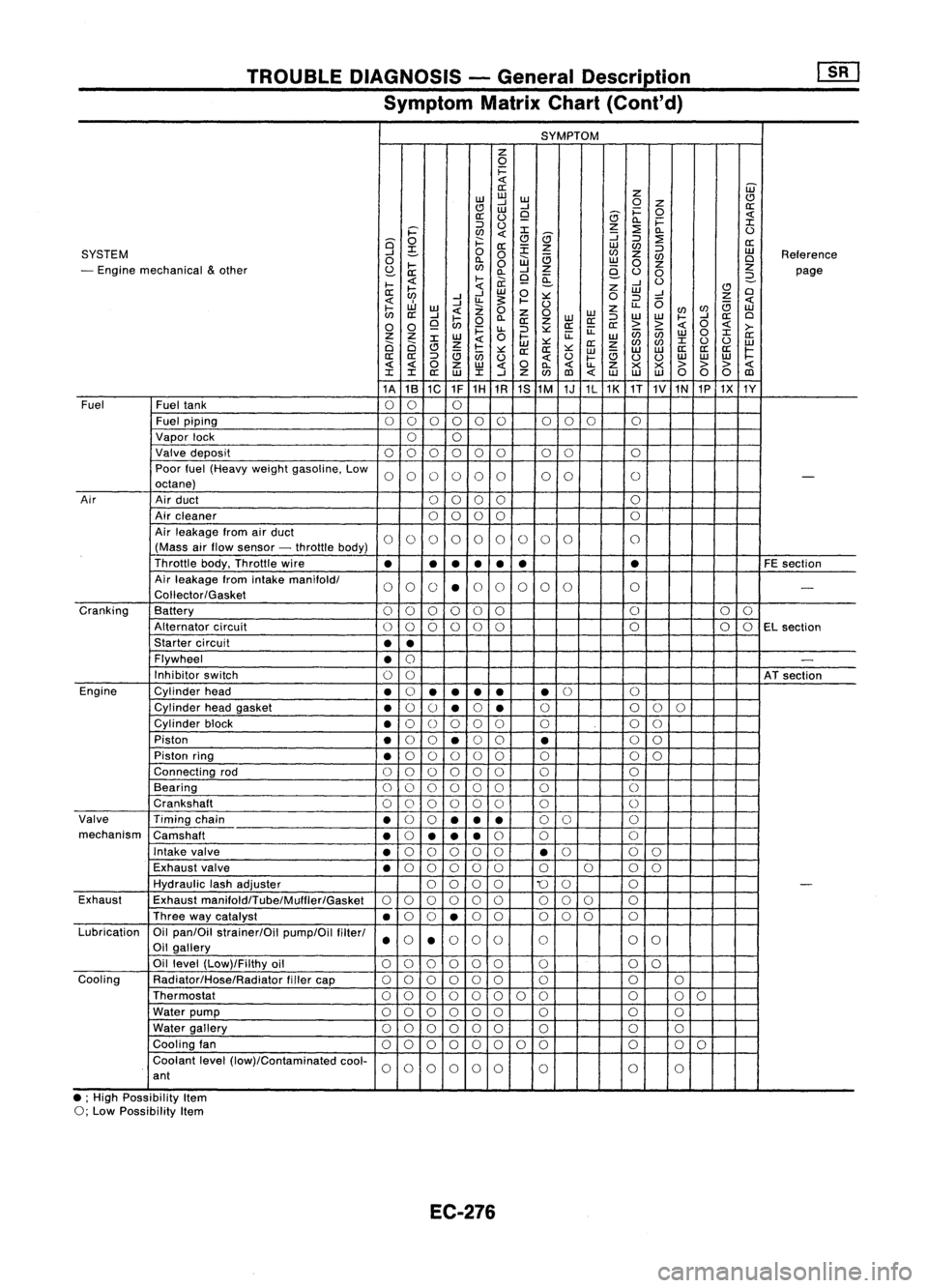
• ;High Possibility Item
0; Low Possibility Item
EC-276
Page 1094 of 1701
VE-TVPEINJECTION PUMP ~
Adjustment (Cont'd)
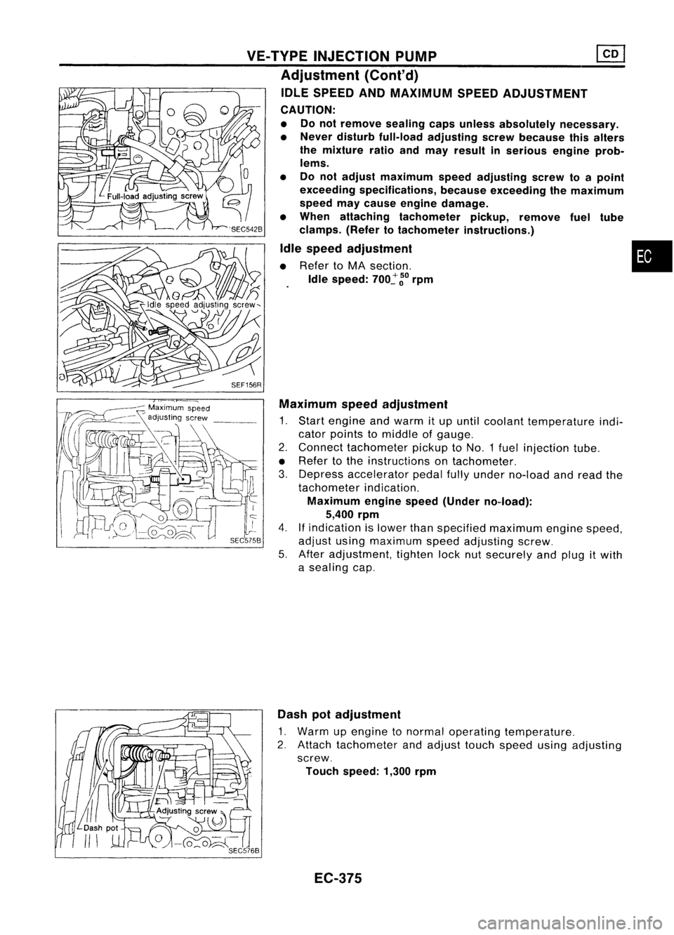
IDLE SPEED ANDMAXIMUM SPEEDADJUSTMENT
CAUTION:
• Donot remove sealingcapsunless absolutely necessary.
• Never disturb full-load adjusting screwbecause thisalters
the mixture ratioandmay result inserious engineprob-
lems.
• Donot adjust maximum speedadjusting screwtoapoint
exceeding specifications, becauseexceeding themaximum
speed maycause engine damage.
• When attaching tachometer pickup,remove fueltUbe
clamps. (Refertotachometer instructions.)
Idle speed adjustment •
• Refer toMA section.
Idle speed:
700~
~o
rpm
SEF156R Maximum speedadjustment
1. Start engine andwarm itup until coolant temperature indi-
cator points tomiddle ofgauge.
2. Connect tachometer pickuptoNO.1 fuelinjection tube.
• Refer tothe instructions ontachometer.
3. Depress accelerator pedalfullyunder no-load andread the
tachometer indication.
Maximum enginespeed(Under no-load):
5,400 rpm
4.
If
indication islower thanspecified maximum enginespeed,
adjust usingmaximum speedadjusting screw.
5. After adjustment, tightenlocknutsecurely andplug itwith
a sealing cap.
Dash potadjustment
1. Warm upengine tonormal operating temperature.
2. Attach tachometer andadjust touchspeed usingadjusting
screw.
Touch speed: 1,300rpm
EC-375
Page 1095 of 1701
Nozzleside
Combustion
chamber side
SEF668A
SEF781A
SEF669A
:S
older ~Adiusting shim
c:,
Nozzlespring
~ '~[;{~I:,""'
pi,",
Nozzle needle~~(''''-
Nozzle bOdyr ~
Nozzle nut)
SEF670A INJECTION
NOZZLE
CAUTION: Plug flare nutwith acap orrag sothat nodust enters thenoz-
zle. Cover nozzle tipfor protection ofneedle.
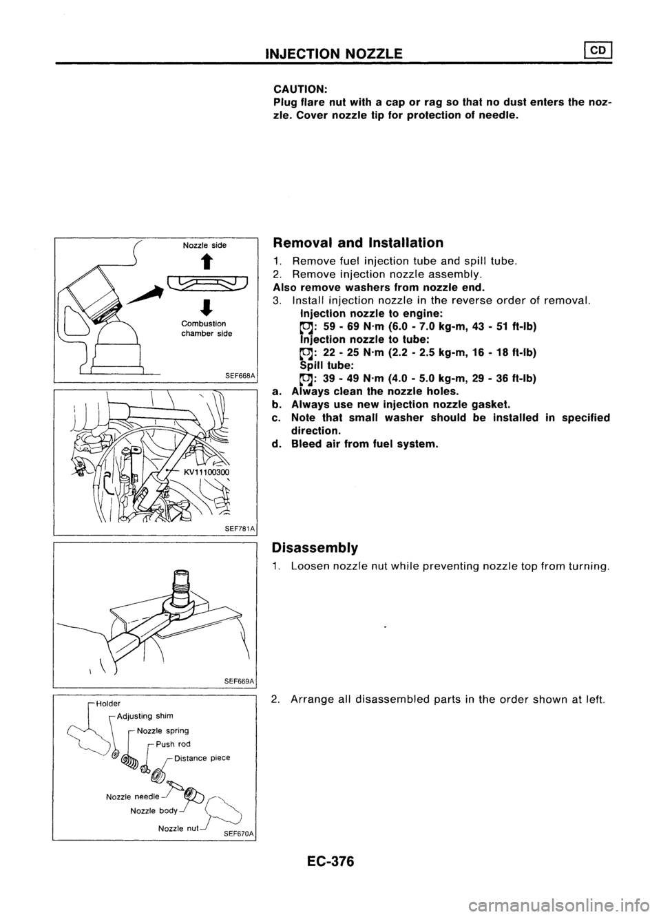
Removal andInstallation
1. Remove fuelinjection tubeandspill tube.
2. Remove injection nozzleassembly.
Also remove washers fromnozzle end.
3. Install injection nozzleinthe reverse orderofremoval.
Injection nozzletoengine:
~: 59-69 N'm (6.0-7.0 kg-m, 43-51 ft-Ib)
Injection nozzletotube:
~: 22-25 N'm (2.2-2.5 kg-m, 16-18 ft-Ib)
Spill tube:
~: 39-49 N'm (4.0-5.0 kg-m, 29-36 ft-Ib)
a. Always cleanthenozzle holes.
b. Always usenew injection nozzlegasket.
c. Note thatsmall washer shouldbeinstalled inspecified
direction.
d. Bleed airfrom fuelsystem.
Disassembly
1. Loosen nozzlenutwhile preventing nozzletopfrom turning.
2. Arrange alldisassembled partsinthe order shown atleft.
EC-376
Page 1199 of 1701
TIMINGCHAIN
Without
VTC
CAUTION:
• After removing timingchain,donot turn crankshaft and
camshaft separately, orvalves willstrike piston heads.
• When installing camshafts, chaintensioner, oilseals, or
other sliding parts,lubricate contacting surfaceswithnew
engine oil.
• Apply newengine oiltobolt threads andseat surfaces when
installing cylinderhead,camshaft sprocket,crankshaft
pulley, andcamshaft brackets.
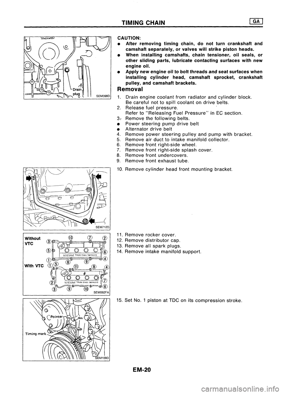
Removal
1. Drain engine coolant fromradiator andcylinder block.
Be careful nottospill coolant ondrive belts.
2. Release fuelpressure. '
Refer to"Releasing FuelPressure" inEG section.
3.. Remove thefollowing belts.
• Power steering pumpdrivebelt
• Alternator drivebelt
4. Remove powersteering pulleyandpump withbracket.
5. Remove airduct tointake manifold collector.
6. Remove frontright-side wheel.
7. Remove frontright-side splashcover.
8. Remove frontundercovers.
9. Remove frontexhaust tube.
10. Remove cylinderheadfrontmounting bracket.
11. Remove rockercover.
12. Remove distributor cap.
13. Remove allspark plugs.
14. Remove intakemanifold support.
15. Set NO.1 piston at
TOG
onitscompression stroke.
EM-20