Page 308 of 1701

ANTI-LOCKBRAKESYSTEM
Purpose
The Anti-Lock BrakeSystem (ABS)consists ofelectronic andhydraulic components. Itallows forcon-
trol ofbraking forcesothat locking ofthe wheels canbeavoided.
The ABS:
1) Improves propertracking performance throughsteering wheeloperation.
2) Eases obstacles tobe avoided throughsteering wheeloperation.
3) Improves vehiclestability bypreventing flatspins.
Operation
• When thevehicle speedisless than 10km/h (6MPH) thissystem doesnotwork.
• The Anti-Lock BrakeSystem (ABS)hasself-test capabilities. Thesystem turnsonthe ABS warning
light for1second afterturning theignition switchON.The system performs anothertestthefirst time
the vehicle reaches 6km/h (4MPH). Amechanical noisemaybeheard asthe ABS performs aself-
test. This isanormal partofthe self-test feature.Ifa malfunction isfound during thischeck, theABS
warning lightwillcome on.
• During ABSoperation, amechanical noisemaybeheard. Thisisanormal condition.
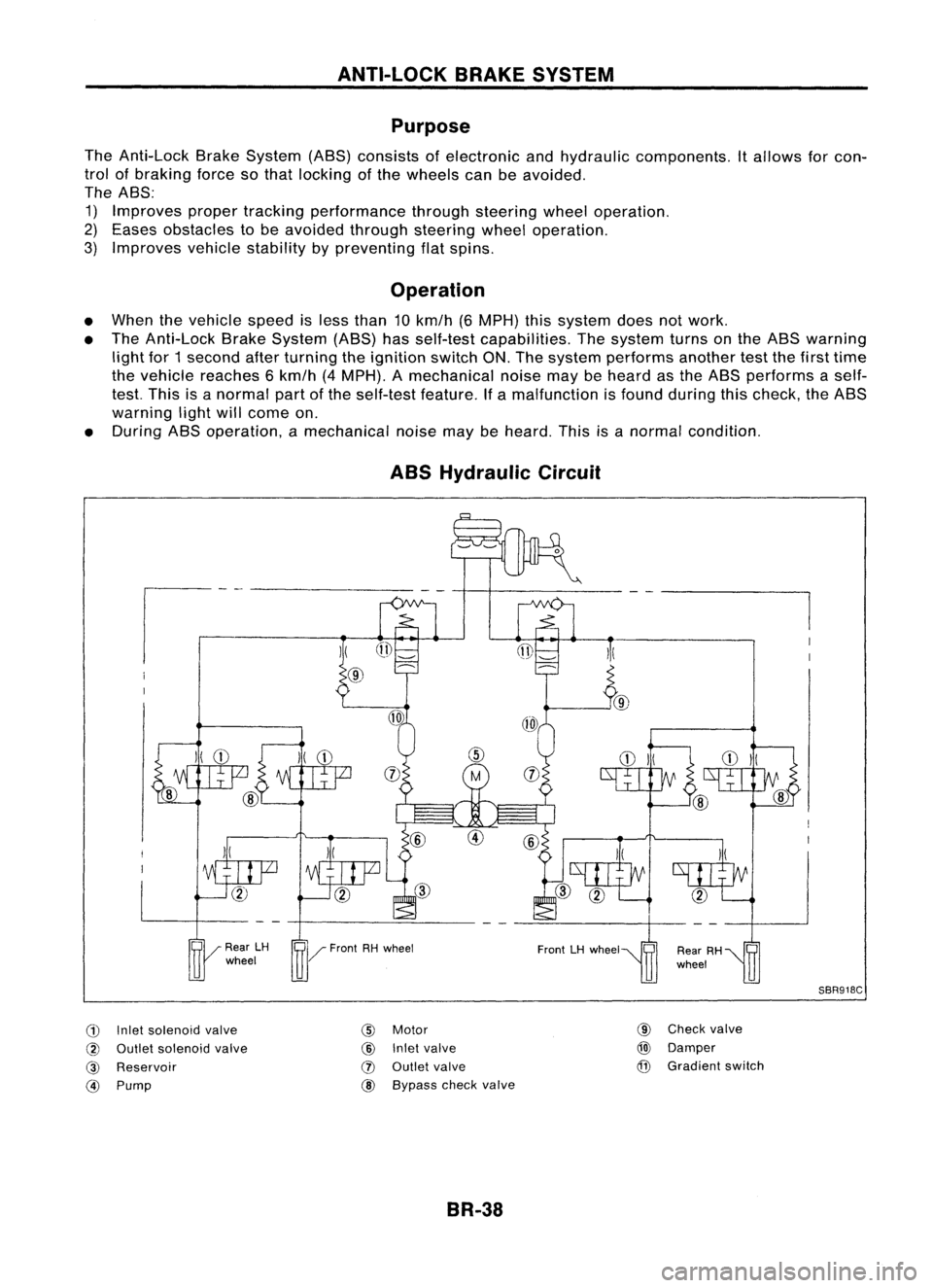
ABS Hydraulic Circuit
G)
Inletsolenoid valve
@
Outlet solenoid valve
@
Reservoir
@)
Pump
)(
@
@
Motor
@
Inletvalve
(J)
Outlet valve
@ Bypass checkvalve
BR-38 @
Check valve
@)
Damper
@
Gradient switch
SBR918C
Page 309 of 1701

ANTI-LOCKBRAKESYSTEM
System Components
Dual proportioning
valve
Rearwheel sensors
For LHD models, controlunit
is located onthe opposite side.
SBR048DB
Control unit
s::';o~'~W.
r
Magnetic flux~ _~-Coil
I .I
Tooth~ Sensorrotor
/ ~m~f onetooth
v:~-- System
Description
SENSOR
The sensor unitconsists ofagear-shaped sensorrotoranda
sensor element. Theelement contains abar magnet around
which acoil iswound. Thesensor isinstalled onthe back side
of the brake rotor.Sine-wave currentisgenerated bythe sen-
sor asthe wheel rotates. Thefrequency andvoltage increase(s) •
as the rotating speedincreases. :•
V: Induced electromotive force
SBR124B
SBR049DA CONTROL
UNIT
The control unitcomputes thewheel rotating speedbythe sig-
nal current sentfrom thesensor. Thenitsupplies aDC current
to the actuator solenoid valve.Italso controls ON-OFFopera-
tion ofthe valve relayandmotor relay.Ifany electrical malfunc-
tion should bedetected inthe system, thecontrol unitcauses
the warning lamptolight up.Inthis condition, theASS willbe
deactivated bythe control unit,andthevehicle's brakesystem
reverts tonormal operation.
BR-39
Page 310 of 1701
ANTI-LOCKBRAKESYSTEM
Removal andInstallation
CAUTION: Be careful nottodamage sensoredgeandsensor rotorteeth.
When removing thefront orrear wheel hubassembly, discon-
nect theABS wheel sensor fromtheassembly andmove it
away.
FRONT WHEEL SENSOR
Front wheel sensor (LH) ~!Ii
3.9-5.9 (0.4 -0.6, 35-52)
~: Nom (kg-m, ft-lb)
~: Nom(kg-m, in-Ib)
SBR030DA
REAR WHEEL SENSOR
BR-40
\
L
Rear wheel sensor (LH)
~: Nom (kg-m, ft-Ib)
~: Nom(kg-m, in-Ib)
SBR031DA
Page 311 of 1701
ANTI-LOCKBRAKESYSTEM
Removal andInstallation (Cont'd)
SENSOR ROTOR
Removal
1. Remove thedrive shaftandrear wheel hub.Refer toFA
section ("DriveShaft",FRONTAXLE") andRAsection
("Wheel Hub",REARAXLE").
2. Remove thesensor rotorusing suitable puller,driftand
bearing replacer.
Suitable drift
SBR873CA
Installation
Install thesensor rotor.Forfront sensor rotor,usehammer and
wooden block.Forrear sensor rotor,usesuitable driftand
press.
• Always replace sensorrotorwithnewone.
SBR985C
•
• Pay attention tothe dimension ofrear sensor rotorasshown
in figure.
h: 4.5 -5.5 mm (0.177 -0.217 in)
CONTROL UNIT
Location: Passenger side,behind dashsidelower finisher.
• Make surethatthesensor shieldground cableissecured
with mounting bolt.
SBR986C
Suitable
drift
B,.,k" ~ ABS
.'0"'" ","
Dash side ~
lower finisher ~3.9_5.9 N.m
(0.4 -0.6 kg-m,
35 -52 In-Ib)
SBR032DA
Rear
sensor rotor
BR-41
Page 313 of 1701
ANTI-LOCKBRAKESYSTEM
Removal andInstallation (Cont'd)
1. Disconnect batterycable.
2. Drain brake fluid.Refer toSR-5.
3. Discharge airconditioner refrigerant.RefertoHA section
("R-134a ServiceProcedure", "SERVICEPROCEDURES").
4. Disconnect allconnectors fromASSrelay bracket.
5. Remove mounting boltforrelay bracket.
6. Remove ASSrelay boxwith bracket.
7. Remove airconditioner low-pressure tubes.RefertoHA
section, ("Refrigerant Lines","SERVICE PROCEDURES") .
8. Disconnect brakepipesandmove awayfromactuator.
It is not necessary toremove thesepipesfromvehicle.
9. Remove/loosen mountingnutsbetween actuatorand
bracket.
BR-43
•
Page 314 of 1701
ANTI-LOCKBRAKESYSTEM
Removal andInstallation (Cont'd)
10. Draw outASS actuator asshown.
ASS
actuator
SBR039D CAUTION:
After installation, payattention tothe following points:
• Refill brake fluidandbleed air.Refer to"CHECK AND
ADJUSTMENT", BR-5and"AIR BLEEDING", BR.6,respec-
tively.
• Charge airconditioner refrigerant.RefertoHA section,
("R-134a ServiceProcedure", "SERVICEPROCEDURES").
• The installation procedureisthe reverse ofremoval.
ASS
actuator
_-=--=--=--=--_-_-\,_~
""'~t"
b"ok.,
SBR040D
ABSRELAYS
1. Disconnect batterycable.
2. Remove ASSrelay cover.
BR-44
Page 315 of 1701
ANTI-LOCKBRAKESYSTEM
Wiring Diagram -ABS -
BR-ABS-01
•
ABS
CONTROL
UNIT
(B111)
LHDmodels
@:
RHOmodels
Refer
to
EL-POWER.
FUSE
BLOCK
(JIB)
~
GY
ffi
IGN
SW
Y
I~I COMBINATION
METER
(ABS WARNING
LAMP)
~@
LIB
@
I
GY
LIB
$-------$
GY (~) LIB
I-
e-
LIB~ ToBR-ABS-O?
I
LIB
13-0
I
FAIL
LAMP
IGNITION
SWITCH
ON orSTART
STOP
DEPRESED LAMP
SWITCH
RELEASED ~
~
P!L
•
~:I
P!L
rn~
I
JUNCTION
BOX
NO.2
(JOINT
CONNECTORS)
1!:i=!J~
PIL
~~
•
PIL
lelIl
9F'~
P!L
14-81
STOP
LAMP
SW
Fa~
l..1..@
B ~~(B115)
5 6
TI1910
1112 W
Refer
tolast page
(Foldout page).
~---------------------------------,
L ~
HBR002
BR-45
Page 316 of 1701
ANTI-LOCKBRAKESYSTEM
Wiring Diagram -ABS -(Coni' d)
BR-ABS-02
ABS
CONTROL
UNIT
(!ID1)
OrAG
L TXD RXD
~ 1~61~
ORIB ~ GY!L GIB
I$~ ~
~ciJ~ ---
~~I
ORIB
GY/L GIB
It It
GY!L
GIB
cr
l I~
i~MO~o~?ic~g~)
~:
JOINT CONNECTOR-5
~ 1*.21~:
GY/L GIB
I I
GY/L
GIB
m
r1l
ORIB
rtl
FUSE
Referto
7 .5A BLOCK EL-POWER.
rn
(JIB)
~
IGNITION
SWITCH
ON orSTART
I
DATALINK
CONNECTOR
FOR CONSULT
(M13)
-----------------------
<0:
LHDmodels
RHOmode Is
@:
GAengine andSRengine
@:
CD20engine
~f1
<0
10
6
*2
<0
9
'
3
,
~~(~)
56j819101112 W
~(~24)
~OR
Refer
tolast page
(Foldout page).
HBR003
BR-46