Page 1488 of 1701
CONTENTS(Cont'd.)
CHASSIS ANDBODY MAINTENANCE 45
Checking ExhaustSystem .45
Checking ClutchFluidLevel andLeaks .45
Checking ClutchSystem .45
Checking MfTOil .45
Changing MfTOil 46
Checking
AfT
Fluid Level .46
Changing
AfT
Fluid .47
Checking BrakeFluidLevel andLeaks 47
Checking BrakeSystem .47
Changing BrakeFluid .47
Checking BrakeBooster, VacuumHoses,
Connections andCheck Valve ~48
Checking DiscBrake .48
Checking DrumBrake .49
Balancing Wheels 49
Ti re Rotation 50
Checking SteeringGearandLinkage 50
Checking PowerSteering FluidandLines 50
Lubricating Locks,Hinges andHood Latches 51
Checking SeatBelts, Buckles, Retractors,
Anchors andAdjusters 51
Checking BodyCorrosion 52
GA
SERVICE DATAANDSPECIFICATIONS
(505)53
Engine Maintenance 53
SR
SERVICE DATAANDSPECIFICATIONS
(505)54
Engine Maintenance 54
CD
SERVICE DATAANDSPECIFICATIONS
(505)55
Engine Maintenance 55
SERVICE DATAANDSPECIFICATIONS
(505)56
Chassis andBody Maintenance 56
Page 1533 of 1701

CHASSISANDBODY MAINTENANCE
OK MINMax,
line
Min, line
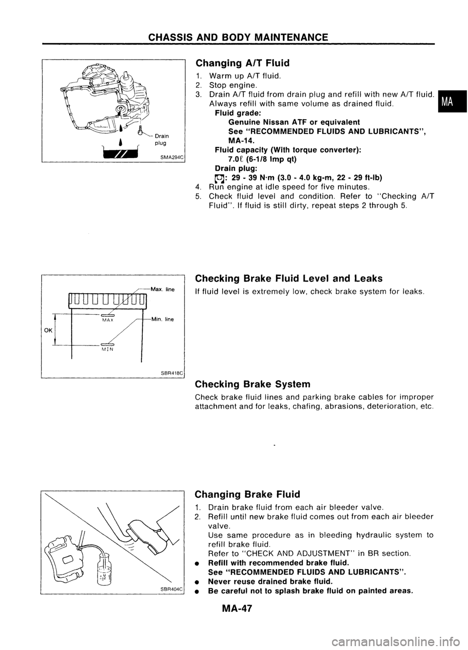
SBR418C Changing
AITFluid
1. Warm up
AIT
fluid.
2. Stop engine.
3. Drain
AIT
fluid from drain plugandrefill withnew
AIT
fluid .•
Always refillwithsame volume asdrained fluid.
i
Fluid grade:
Genuine NissanATForequivalent
See "RECOMMENDED FLUIDSANDlUBRICANTS",
MA-14.
Fluid capacity (Withtorque converter):
7.0£
(6-1/8
Impqt)
Drain plug:
toJ:
29.39
N'm
(3.0-4.0
kg-m,
22-29
ft-Ib)
4. Run engine atidle speed forfive minutes.
5. Check fluidlevel andcondition. Referto"Checking
AIT
Fluid". Iffluid isstill dirty, repeat steps2through 5.
Checking BrakeFluidLevel andLeaks
If
fluid level isextremely low,check brakesystem forleaks.
Checking BrakeSystem
Check brakefluidlines andparking brakecables forimproper
attachment andforleaks, chafing, abrasions, deterioration, etc.
SBR404C Changing
BrakeFluid
1. Drain brake fluidfrom each airbleeder valve.
2. Refill untilnewbrake fluidcomes outfrom each airbleeder
valve. Use same procedure asinbleeding hydraulic systemto
refill brake fluid.
Refer to"CHECK ANDADJUSTMENT" inBR section.
• Refill withrecommended brakefluid.
See "RECOMMENDED FLUIDSANDlUBRICANTS".
• Never reusedrained brakefluid.
• Becareful nottosplash brakefluidonpainted areas.
MA-47
Page 1615 of 1701
SRA711A
SRA712A REAR
AXLE
Wheel Hub(Conl'd)
1. Remove brakecaliper assembly.
2. Remove wheelbearing locknut.
3. Remove brakerotor(models withdiscbrake) orbrake drum
(models withdrum brakes).
4. Remove wheelhubbearing fromspindle.
Brake hosedoes notneed tobe disconnected frombrake cali-
per.
Suspend caliperassembly withwire soas not tostretch brake
hose.
Be careful nottodepress brakepedal, orpiston willpop out.
Make surebrake hoseisnot twisted.
INSTALLATION
• Install wheel hubbearing.
• Tighten wheelbearing locknut.
Before tightening, applyoiltothreaded portionofrear spin-
dle and both sides ofplain washer.
~: 186-255 N'm (19-26 kg-m, 137-188 ft-Ib)
• Check thatwheel bearings operatesmoothly.
• Check wheelhubbearing axialendplay.
Axial endplay:
0.05 mm(0.0020 in)orless
RA-7
•
Page 1617 of 1701

SRA696A
SRA697A
S
Control rod
Lateral link
~H";""I"
ITorsion
beam
SRA698AREAR
SUSPENSION
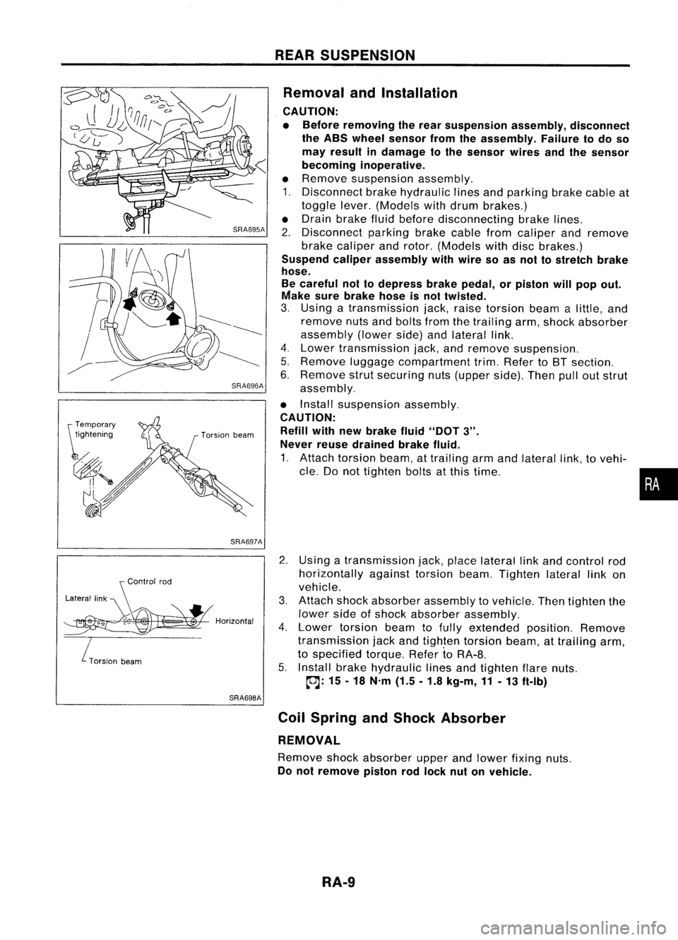
Removal andInstallation
CAUTION:
• Before removing therear suspension assembly,disconnect
the ABS wheel sensor fromtheassembly. Failuretodo so
may result indamage tothe sensor wiresandthesensor
becoming inoperative.
• Remove suspension assembly.
1. Disconnect brakehydraulic linesandparking brakecableat
toggle lever.(Models withdrum brakes.)
• Drain brake fluidbefore disconnecting brakelines.
2. Disconnect parkingbrakecablefromcaliper andremove
brake caliper androtor. (Models withdiscbrakes.)
Suspend caliperassembly withwire soasnot tostretch brake
hose.
Be careful nottodepress brakepedal, orpiston willpop out.
Make surebrake hoseisnot twisted.
3. Using atransmission jack,raise torsion beamalittle, and
remove nutsandbolts fromthetrailing arm,shock absorber
assembly (lowerside)andlateral link.
4. Lower transmission jack,andremove suspension.
5. Remove luggagecompartment trim.Refer toBT section.
6. Remove strutsecuring nuts(upper side).Thenpulloutstrut
assembly.
• Install suspension assembly.
CAUTION: Refill withnewbrake fluid"DOT
3".
Never reusedrained brakefluid.
1. Attach torsion beam,attrailing armandlateral link,tovehi-
cle. Donot tighten boltsatthis time.
2. Using atransmission jack,place lateral linkand control rod
horizontally againsttorsionbeam.Tighten laterallinkon
vehicle.
3. Attach shockabsorber assembly tovehicle. Thentighten the
lower sideofshock absorber assembly.
4. Lower torsion beamtofully extended position.Remove
transmission jackandtighten torsion beam,attrailing arm,
to specified torque.RefertoRA-8.
5. Install brakehydraulic linesandtighten flarenuts.
~: 15-18 N'm (1.5.1.8 kg-m,11-13 ft-Ib)
Coil Spring andShock Absorber
REMOVAL
Remove shockabsorber upperandlower fixing nuts.
Do not remove pistonrodlock nutonvehicle.
RA-9
•