Page 294 of 1701
FRONTDISCBRAKE
Installation
CAUTION:
• Refill withnewbrake fluid"DOT 3"or"DOT 4".
• Never reusedrained brakefluid.
• Donot mix different typesofbrake fluids(DOT3,DOT 4).
1. Install caliper assembly.
2. Install brakehosetocaliper securely.
3. Install allparts andsecure allbolts.
4. Bleed air.Refer to"Bleeding Procedure", BR-6.
BR-24
Page 298 of 1701
SBR216B
~ ~Vohi'" 'COol
DepreSSi~~
"
~
/
SBR217B
SBR279B
REAR
DRUM BRAKE
Installation (Cont'd)
2. Apply brake grease tothe contact areasshown atleft.
3. Shorten adjuster byrotating it.
• Pay attention todirection ofadjuster.
Wheel Screw Depression
Left Left-handthread
Yes
Right Right-handthread No
4. Connect parkingbrakecabletotoggle
lever.
5. Install allparts.
Be careful nottodamage wheelcylinder pistonboots.
6. Check allparts areinstalled properly.
Pay attention todirection ofadjuster assembly.
7. Install brakedrum.
8. When installing newwheel cylinder oroverhauling wheel
cylinder, bleedair.Refer to"Bleeding procedure", BR-6.
9. Adjust parking brake.RefertoBR-37.
BR-28
Page 305 of 1701
SBR646REAR
DISCBRAKE
Assembly (Cont'd)
8. Insert piston sealintogroove oncylinder body.
9. With piston bootfitted topiston, insertpiston bootinto
groove oncylinder bodyandfitpiston byturning itclock-
wise withlong nose pliers, orsuitable tool.
Commercial
service
1001
SBR868C
10.Fittoggle lever,return spring andcable guide.
Installation
CAUTION:
• Refill withnewbrake fluid"DOT 3"or"DOT
4".
• Never reusedrained brakefluid.
• Donot mix different typesofbrake fluids(DOT3,DOT
4).
1. Install caliper assembly.
2. Install brakehosetocaliper securely.
3. Install allparts andsecure allbolts.
4. Bleed air.Refer to"Bleeding Procedure", BR-6.
BR-35
•
Page 314 of 1701
ANTI-LOCKBRAKESYSTEM
Removal andInstallation (Cont'd)
10. Draw outASS actuator asshown.
ASS
actuator
SBR039D CAUTION:
After installation, payattention tothe following points:
• Refill brake fluidandbleed air.Refer to"CHECK AND
ADJUSTMENT", BR-5and"AIR BLEEDING", BR.6,respec-
tively.
• Charge airconditioner refrigerant.RefertoHA section,
("R-134a ServiceProcedure", "SERVICEPROCEDURES").
• The installation procedureisthe reverse ofremoval.
ASS
actuator
_-=--=--=--=--_-_-\,_~
""'~t"
b"ok.,
SBR040D
ABSRELAYS
1. Disconnect batterycable.
2. Remove ASSrelay cover.
BR-44
Page 353 of 1701

TROUBLEDIAGNOSES
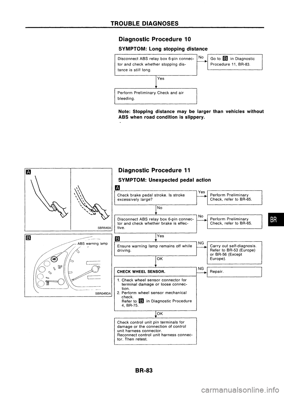
Diagnostic Procedure10
SYMPTOM: Longstopping distance
Disconnect ABSrelay box6-pin connec- No
tor and check whether stopping dis-
tance isstill long.
Perform Preliminary Checkandair
bleeding. Go
to
IiJ
inDiagnostic
Procedure 11.SR-83.
Note: Stopping distancemaybelarger thanvehicles without
ABS when roadcondition isslippery.
Diagnostic Procedure11
SYMPTOM: Unexpected pedalaction
m
Check brakepedalstroke. Isstroke
excessively
large?
No
Disconnect ASSrelay box6-pin connec-
tor and check whether brakeiseffec-
SBR540A tive.
Yes
Ensure warning lampremains offwhile
driving.
OK
CHECK WHEEL SENSOR.
1. Check wheelsensor connector for
terminal damageorloose connec-
tion.
2. Perform wheelsensor mechanical
check. Refer to
IiJ
inDiagnostic Procedure
4, BR-75.
OK
Check control unitpinterminals for
damage orthe connection ofcontrol
unit harness connector.
Reconnect controlunitharness connec-
tor. Then retest.
BR-83
Yes
Perform Preliminary
Check. refertoSR-65.
Perform Preliminary
Check. refertoSR-65.
Carry outself-diagnosis.
Refer toBR-53 (Europe)
or SR-56 (Except
Europe).
Repair.
•
Page 363 of 1701

INSPECTIONANDADJUSTMENT
Pedal stopper
Dash lower
panel (except
CD20 engine //
model)
/L
Floor car-pet
L
Dash reinforcement panel
(CD20 engine model)
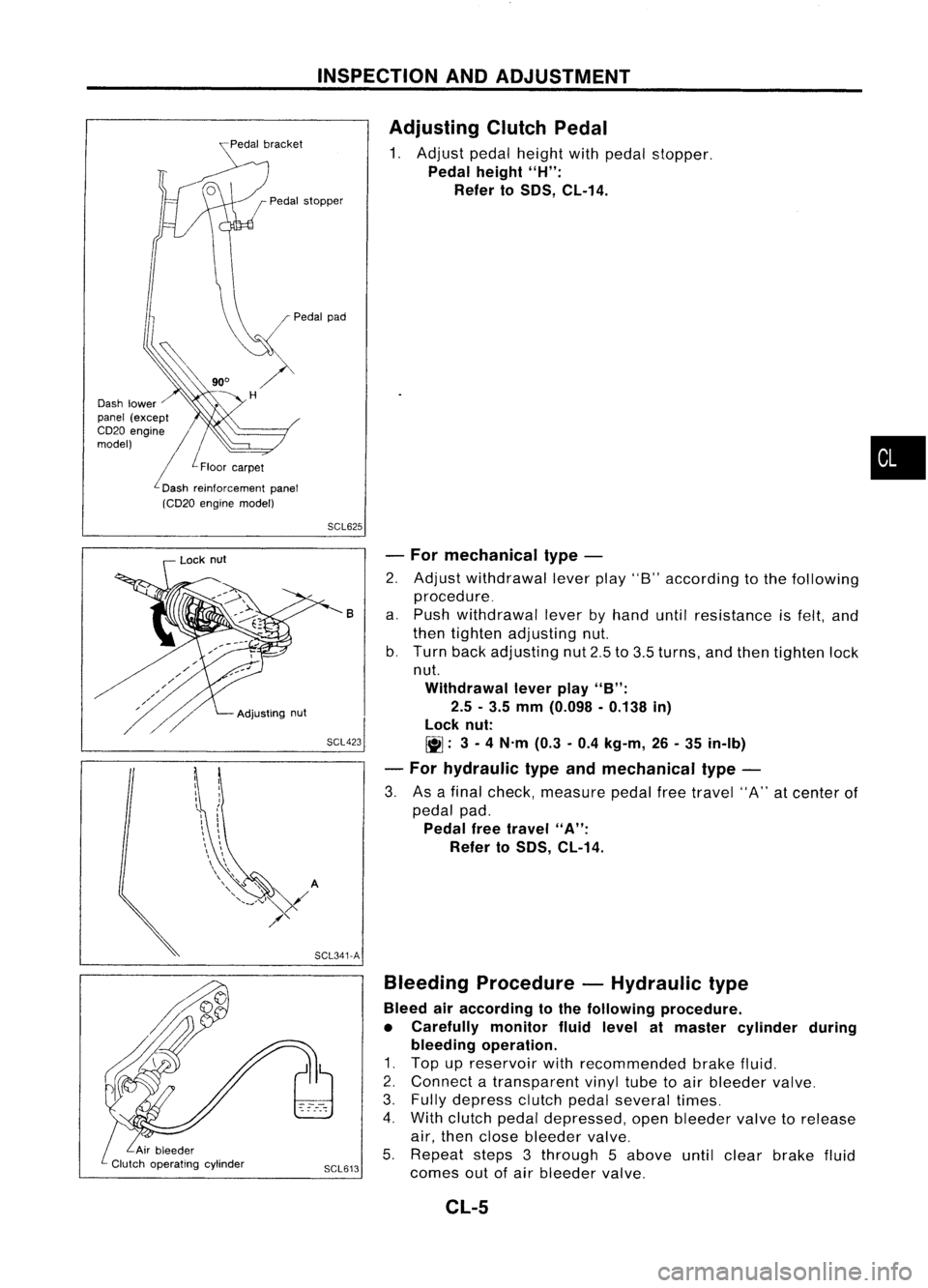
Adjusting
ClutchPedal
1. Adjust pedalheight withpedal stopper.
Pedal height
"H":
Refer to
50S,
CL-14.
•
SCL625
SCL423 -
For mechanical type-
2. Adjust withdrawal leverplay"8"according tothe following
procedure_
a. Push withdrawal leverbyhand untilresistance isfelt, and
then tighten adjusting nut.
b. Turn backadjusting nut2.5to3.5 turns, andthen tighten lock
nut.
Withdrawal leverplay
"B":
2.5 -3.5 mm (0.098 -0.138 in)
lock nut:
~: 3-
4 N'm (0.3-0.4 kg-m, 26-35 in-Ib)
- For hydraulic typeandmechanical type-
3. Asafinal check, measure pedalfreetravel "A"atcenter of
pedal pad.
Pedal freetravel
"A":
Refer to
50S,
CL-14.
B
Bleeding Procedure -Hydraulic type
Bleed airaccording tothe following procedure.
• Carefully monitorfluidlevel atmaster cylinder during
bleeding operation.
1. Top upreservoir withrecommended brakefluid.
2. Connect atransparent vinyltubetoair bleeder valve.
3. Fully depress clutchpedalseveral times.
4. With clutch pedaldepressed, openbleeder valvetorelease
air, then close bleeder valve.
5. Repeat steps3through 5above untilclear brake fluid
SCL613
comesoutofair bleeder valve.
SCL341-A
Adjusting
nut
Lock
nut
CL-5
Page 1274 of 1701
![NISSAN ALMERA N15 1995 Service Manual CYLINDERHEAD
ill]
Assembly (Cont'd)
10. Install valvecomponent parts.
• Install valves withlarger diameter headonthe intake side.
•
Wide pitch
Narrow pitch
Paint mark
Cylinder headside
S NISSAN ALMERA N15 1995 Service Manual CYLINDERHEAD
ill]
Assembly (Cont'd)
10. Install valvecomponent parts.
• Install valves withlarger diameter headonthe intake side.
•
Wide pitch
Narrow pitch
Paint mark
Cylinder headside
S](/manual-img/5/57349/w960_57349-1273.png)
CYLINDERHEAD
ill]
Assembly (Cont'd)
10. Install valvecomponent parts.
• Install valves withlarger diameter headonthe intake side.
•
Wide pitch
Narrow pitch
Paint mark
Cylinder headside
SEM085D•
Always usenew valve oilseal.
Refer toOIL SEAL REPLACEMENT.
• Before installing valveoilseal, install valvespring seat.
.' Install valvespring (uneven pitchtype) withitsnarrow
pitched sidetoward cylinder headside(paint mark).
• After installing valvecomponent parts,tapvalve stemtip
with plastic hammer toassure aproper fit.
11. Check hydraulic lashadjusters.
a. Push rocker armathydraulic lashadjuster location, andsee
if rocker armmoves. Ifitmoves atleast 1mm (0.04 in),it
indicates thatthere isair inthe high pressure chamber.
Noise willbeemitted fromhydraulic lashadjuster ifengine
is started without bleeding air.
b. Remove hydraulic lashadjuster anddipinacontainer filled
with engine oil.While pushing plungerasshown infigure,
lightly pushcheck ballusing athin rod. Airiscompletely
bled when plunger nolonger moves.
Air cannot bebled from thistype oflash adjuster byrunning the
engine.
SEM093D
• rEngine oil
- - , t-=1=i
Proper
rod
SEM772C
Rocker arm9UVide
Rock~rarm
Shim
Hydraulic
I
.,h
.dj"'"
i\\ j
12.
Install rocker arms,shims, rockerarmguides andhydrau-
lic lash adjusters.
CAUTION: Install allparts intheir original positions.
SEM202D EM-95
Page 1307 of 1701
CYLINDERHEAD
SEC. 111-130-135
[O.J
87-107 (8.9 -10.9, 64-79)
/ Swirl chamber
(Combustion chamber)
Valve seat
[O.J
87•107 (8.9 -10.9, 64-79)
~ :N.m (kg-m, in-Ib)
[O.J :
N. m (kg-m, ft-Ib)
f] :
Lubricate withnewengine oil.
SEM226F
G)
Camshaft
@
Front oilseal
@
Collar
@
Grommet
@
Front backcover
@ Front camshaft sprocketplate
(J)
Front camshaft sprocket
@
Spring
@
Selective cylinderheadgasket
@)
Valve
@
Spring seat
@
Valve spring
@ Valve oilseal
@ Spring retainer (INT)/Valve
rotator (EXH)
@
Valve cotter
@
Hydraulic valvelifter
@ Rear backcover
@
Rear camshaft sprocket
@
Grommet
@)
Collar
@ Rocker covergasket
@
Cam bracket
@ Rear oilseal
For hydraulic valvelifter
• Before starting engine,makesurethatvalve doesnothitpiston whenrotating crankshaft byhand.
• When bleeding airout from hydraulic valvelifter,runengine atmore than2,400 rpmfor20minutes
or more.
EM-128